IFM Electronic Efector 600 TADx91 Series User manual

Operating instructions
Temperature transmitter
TADx81
TADx91
706180 / 00 11 / 2012
UK

2
Contents
1 Preliminary note���������������������������������������������������������������������������������������������������3
1�1 Symbols used ������������������������������������������������������������������������������������������������3
2 Safety instructions �����������������������������������������������������������������������������������������������4
3 Functions and features ����������������������������������������������������������������������������������������4
3�1 Applications ���������������������������������������������������������������������������������������������������4
4 Functionality���������������������������������������������������������������������������������������������������������5
4�1 Communication, parameter setting, evaluation ���������������������������������������������5
4�2 Operating modes �������������������������������������������������������������������������������������������5
4�3 Monitoring and diagnostic functions ��������������������������������������������������������������6
4�3�1 Drift / fault monitoring ��������������������������������������������������������������������������6
4�3�2 Sensor backup / redundancy switching ������������������������������������������������6
4�4 Analogue function ������������������������������������������������������������������������������������������7
4�4�1 Behaviour in case of exceeding or not reaching the limits of the meas-
uring range �����������������������������������������������������������������������������������������������������7
4�5 Operating mode: 2-wire temperature transmitter�������������������������������������������8
4�5�1 Availability groups in 2-wire operation [drEd]����������������������������������������8
4�5�2 Setting of the analogue value in case of diagnosis [FOU2]������������������8
4�6 Operating mode: 3-wire temperature transmitter with diagnostic switching
output��������������������������������������������������������������������������������������������������������������������9
4�6�1 Availability groups in 3-wire operation [drEd]����������������������������������������9
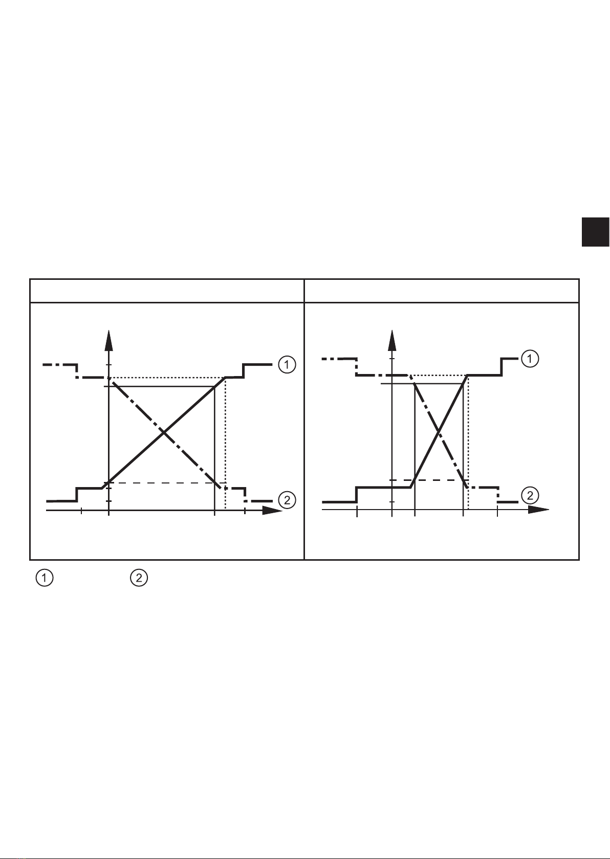
4�6�2 Switching characteristics output 1 in case of diagnosis [dOU1] ��������10
5 Installation ���������������������������������������������������������������������������������������������������������12
5�1 Installation of units with G1 process connection������������������������������������������12
5�2 Installation of units with G½ process connection�����������������������������������������14
6 Electrical connection������������������������������������������������������������������������������������������15
7 Parameter setting ����������������������������������������������������������������������������������������������16
7�1 Adjustable parameters���������������������������������������������������������������������������������17
7�2 General parameter setting���������������������������������������������������������������������������17
7�2�1 Define the analogue signal �����������������������������������������������������������������17
7�2�2 Scaling of the analogue value ������������������������������������������������������������18
7�2�3 Min� / max� values for the system temperature�����������������������������������18
7�2�4 Define drift warning threshold�������������������������������������������������������������18
7�2�5 Define drift alarm threshold ����������������������������������������������������������������18

3
UK
1 Preliminary note
1.1 Symbols used
►Instructions
> Reaction, result
[…] Designation of pushbuttons, buttons or indications
→Cross-reference
Important note
Non-compliance can result in malfunction or interference�
7�2�6 Drift failure threshold �������������������������������������������������������������������������18
7�2�7 Definition of the switching characteristics of the diagnostic output�����18
7�2�8 Setting of the error behaviour of the analogue output ������������������������19
7�2�9 Setting of the characteristics of the redundancy switching�����������������19
7�2�10 Setting of the delay of the drift detection ������������������������������������������19
7�2�11 Set switching logic for OUT1 ������������������������������������������������������������19
7�2�12 Setting of the standard unit of measurement for temperature ����������19
7�2�13 Read error number ���������������������������������������������������������������������������19
7�2�14 Reset all parameters to factory setting ���������������������������������������������19
7�2�15 Settings for communication operation ����������������������������������������������19
8 Operation�����������������������������������������������������������������������������������������������������������20
9 Troubleshooting �������������������������������������������������������������������������������������������������20
9�1 Fault indications�������������������������������������������������������������������������������������������20
10 Scale drawing ��������������������������������������������������������������������������������������������������22
10�1 Units with G1 process connection (TAD*81)���������������������������������������������22
10�2 Units with G½ process connection (TAD*91)���������������������������������������������23
11 Technical data ��������������������������������������������������������������������������������������������������24
11�1 Temperature resistance �����������������������������������������������������������������������������25
12 Factory setting �������������������������������������������������������������������������������������������������25

4
2 Safety instructions
• Please read this document prior to set-up of the unit� Ensure that the product is
suitable for your application without any restrictions�
• If the operating instructions or the technical data are not adhered to, personal
injury and/or damage to property can occur�
• Checkthecompatibilityoftheproductmaterials(→11Technicaldata)withthe
media to be measured in all applications�
3 Functions and features
The unit detects the system temperature in installations�
3.1 Applications
To ensure long-term stability and high accuracy of the unit during operation,
please note:
►Min� insertion depth of the measuring probe: 25 mm�
►The following limit values must be observed:
(→11Technicaldata)
Measuring range -25 ��� +160°C* -13 ��� 320°F
Operating temperature of the process con-
nection
-32 ��� +170°C -25�6 ��� 338°F
Ambient temperature -25 ��� +70°C -13 ��� 158°F
Storage temperature -40 ��� +85°C -40 ��� 185°F
Operating pressure of the medium ≤50bar ≤725PSI
Number of temperature cycles (135K / 7s) < 3000
*→11.1Temperatureresistance

5
UK
4 Functionality
4.1 Communication, parameter setting, evaluation
• The unit generates output signals according to the parameter settings�
• Using an IO-Link capable parameter setting tool such as the FDT service
program ifm Container the following options are available:
- Reading current process values�
- Reading, changing and saving current parameter settings and transmitting
them to other units of the same type�
The catalogue of the available DTM objects, the IO-Link Unit Description
(IODD) and the FDT service program ifm Container can be downloaded at
www.ifm.com→Service→Download.
4.2 Operating modes
1
2-wire temperature transmitter
The unit provides a temperature-proportional output signal (4���20 mA or 20���4 mA)�
Themeasuringrangeisscalable→4.4Analoguefunction.
In addition, the analogue output for diagnosis can be used according to NAMUR
NE43� Since the diagnostic output is not available in this operating mode, it is not
possible to display all error states of the unit�
2
Temperature transmitter with diagnostic output (3-wire operation)
In addition to the analogue signal the unit provides a diagnostic signal� Sensitivity and
reaction to different error modes can be programmed�
Pin 4 = output for diagnostic signal (pnp or npn)�
3
Communication mode (3-wire operation)
The sensor is designed for communication with the PC or PLC via IO-Link� For com-
munication with a PC, the FDT service program ifm Container is available�
For communication mode, no parameter setting is necessary� Using pin 4 (data chan-
nel), data can be read in and out at any time�

6
4.3 Monitoring and diagnostic functions
• By measuring with two different, thermically coupled sensor elements (NTC,
PT 1000) the unit automatically detects drifts and errors during temperature
measurement with great reliability�
• An average value is formed from the measured individual NTC and Pt 1000
values� This average value is the basis for the provided measured value and
also the basis for the drift warning threshold [drW], the drift alarm threshold
[drA] and the drift failure threshold [drF] derived from the drift alarm threshold�
• If one of the two sensor elements fails, the temperature measurement can be
continued with the second element (backup function)�
• Very long-term stable measurement is achieved by using high-quality sensor
elements�
4.3.1 Drift / fault monitoring
To monitor the drift the unit compares the temperatures of two different sensor ele-
ments that are thermically coupled in the sensor tip� Normally these temperatures
are identical�
Due to the usual manufacturing tolerances a temperature difference of max� 0�1 K
can also occur with new sensor elements� This does not affect the drift monitoring
function�
If there is a drift in one or both sensor elements, the unit detects them due to the
difference between the two measured temperatures� It compares the average
value of the two temperatures with the set warning / alarm thresholds [drW], [drA]
→7.2.4;→7.2.5.
If the thresholds are exceeded, it generates corresponding diagnostic messages
and sets the corresponding status for the process value�
In case of high temperature changes in the measured medium (e�g� filling of a
hot medium into a cold vessel) there may be a short-term difference between the
temperatures of both measuring elements� To suppress this effect, the delay can
be changed via the parameter [ddr]�
4.3.2 Sensor backup / redundancy switching
If one of the two temperature measuring channels fails (e�g� short circuit of one of
the two sensor elements), the temperature can still be measured with the channel
which is still operational (sensor backup)� However, drift monitoring is not possible
any more�

7
UK
The behaviour of the unit, e�g�, in case of failure of one of the two measuring ele-
mentsisdefinedbytheparameter[drEd]→8Operation.
4.4 Analogue function
• [OU2] defines whether the set measuring range is provided as 4���20 mA
([OU2] = [I]) or as 20���4 mA ([OU2] = [InEG])�
• The analogue start point [ASP] defines at which measured value the output
signal is 4 mA (20 mA for [InEG])�
• The analogue end point [AEP] defines at which measured value the output
signal is 20 mA (4 mA for [InEG])�
Minimum distance between [ASP] and [AEP] = 5 K�
Factory setting Measuring range scaled
+150 +160
20
4
3,6
21,1
20,5
3,8
I [mA]
0-25 T [°C] +160
20
4
3,6
21,1
20,5
3,8
I [mA]
-25 ASP AEP0 T [°C]
:[OU2]=[I]; : [OU2] = [InEG]
4.4.1 Behaviour in case of exceeding or not reaching the limits of the meas-
uring range
• Measured temperature above the set measuring range (AEP):
- The output signal rises to max� 20�5 mA / falls to min� 3�8 mA�
- If the measured temperature rises any further, a message may be signalled to
thecontrollerdependingonthesettingofthemenuitem[drEd](→8Opera-
tion)�
• Measured temperature below the set measuring range (ASP):
- The output signal falls to min� 3�8 mA / rises to max� 20�5 mA�

8
- If the measured temperature falls any further, a message may be signalled to
thecontrollerdependingonthesettingofthemenuitem[drEd](→8Opera-
tion)�
4.5 Operating mode: 2-wire temperature transmitter
4.5.1 Availability groups in 2-wire operation [drEd]
Using [drEd] it can be set which recognised diagnosis types can be passed on via
the current output (setting via FDT service program)�
Table 1: Availability groups in 2-wire operation
[drEd] Warning Alarm Failure
= [ON]
Maximum availability ●
= [ONdr]
High operational reliability at
good availability (factory setting)
● ●
= [OFF]
Maximum sensor sensitivity ●●●
4.5.2 Setting of the analogue value in case of diagnosis [FOU2]
In 2-wire operation there is a diagnostic message when the actual process value
is no longer provided but instead a defined current value to Namur NE43� Two
settings are available:
Table 2: Defined analogue value for diagnostics
[FOU2] Analogue value for diagnostics
= [ON] 21�1 mA (factory setting)
= [OFF] 3�6 mA

9
UK
4.6 Operating mode: 3-wire temperature transmitter with dia-
gnostic switching output
4.6.1 Availability groups in 3-wire operation [drEd]
Types of diagnostic to be signallled via the current or diagnostic switching output
can be set using [drEd] (setting via FDT service program)�
Since in 3-wire operation all diagnostic messages can be transferred via
the switching output, the current output only leaves its process value trans-
fer in case of a failure� This ensures maximum use of the analogue output�
Table 3 Availability groups in 3-wire operation
[drEd] Warning Alarm Failure
= [ON]
Maximum availability
OU2
(current output) ●
OU1
(switching output) ●
= [ONdr]
High operational reliability
at good availability (factory
setting)
OU2
(current output) ●
OU1
(switching output) ● ●
= [OFF]
Maximum sensor sensitivity
OU2
(current output) ●
OU1
(switching output) ● ● ●

10
4.6.2 Switching characteristics output 1 in case of diagnosis [dOU1]
The behaviour of the diagnostic output OU1 is independent of the analogue output
OU2 and can be configured as below:
Table 4 Switching characteristics output 1 in case of diagnostics
[dOU1] Normal* Warning Alarm or
failure
= nc
normally closed
= nc+
normally closed, extended
(factory setting)
2 Hz
= no+
normally open, extended
2 Hz
= Hb
heartbeat
4 Hz 2 Hz
* no diagnosis message

11
UK
Table 5 Types of diagnosis
Case of diagnosis Warning Alarm Failure
Drift warning threshold [drW]
exceeded (factory setting: 0�2 °C) ●
Limit temperature internal elec-
tronics exceeded (+90°C) ●
Drift alarm threshold [drA] ex-
ceeded (factory setting: 0�5 °C) ●
Failure of one of the two sensor
elements (interruption / short
circuit)
●
Process value does not reach
the analogue start point [ASP] or
exceeds the analogue end point
[AEP]→4.4Analoguefunction
●
Supply voltage outside the oper-
ating range ●
Failure of both sensor elements
(interruption / short circuit)
Or
general electronics problems
(partial malfunction in the sensor
electronics)
●
Fault during parameter setting of
the IO-Link ●
Drift failure threshold [drF] >
drift alarm threshold [drA] + 3 K ●

12
5 Installation
Before installing and removing the unit: Make sure that no pressure is ap-
plied to the system and there is no medium in the pipe� Take into account
possible dangers which may arise from extreme plant/medium tempera-
tures�
5.1 Installation of units with G1 process connection
The unit can be fixed to different process connections� Options are as follows:
1 Installation using an adapter with sealing ring (order no. E332xx / E333xx)
The adapter is supplied with EPDM O-ring (order no� E30054)� More sealing rings are
availableasaccessories:FKMO-ring(orderno.E30123);PEEKsealingring(order
no� E30124)�
Ontheinstallationprocess→Installationinstructionsenclosedtotheadapter.
2 Installation using an adapter with metal-to-metal seal (order no. E337xx /
E338xx)
Ontheinstallationprocess→Installationinstructionsenclosedtotheadapter.
3 Installation using a welding adapter (e.g. order no. E30122)
The adapter is supplied with an EPDM O-ring� More sealing rings are available as
accessories: FKM O-ring, order no� E30123�
Ontheinstallationprocess→Installationinstructionsenclosedtotheadapter.
4 Installation to G 1 flange
The sealing ring on the sensor is used as process seal�
The upper sealing area on the process connection must be flush with the tapped hole
and have a surface characteristic of min� Rz 6�3�
►Grease the sensor thread with a suitable paste�
►Insert the unit into the process connection�
►Tighten it using a spanner� Tightening torque: 35 Nm�

13
UK
≥ 25
Use in hygienic areas to EHEDG
►Make sure that the sensors are
integrated into the system in ac-
cordance with EHEDG�
• Recommended minimum insertion
depth of the sensor into the me-
dium:≥25mm.

14
5.2 Installation of units with G½ process connection
≥ 25
Installation in G½ adapter�
(Alternative for Aseptoflex units: instal-
lation in Aseptoflex Vario adapter�)
►Slightly grease the contact areas
between the sensor and adapter
using a lubricating paste which
is suitable and approved for the
application�
For information on the use of the
adapter please refer to the instructions
enclosed to the adapter�
• Recommended minimum insertion
depth of the sensor into the me-
dium:≥25mm.
• Recommended tightening torque:
30���50 Nm�

15
UK
6 Electrical connection
The unit must be connected by a qualified electrician�
The national and international regulations for the installation of electrical
equipment must be adhered to�
Voltage supply to EN 50178, SELV, PELV / "supply class 2" to cULus�
►Disconnect power�
►Connect the unit as follows:
2-wire operation 3-wire operation:
2-wire operation pin 1 Ub+
pin 2 Ub-
3-wire operation:
pin 1 Ub+
pin 3 Ub-
pin 2 (OUT2) •Analogue output for system temperature
pin 4 (OUT1) •diagnostic output
•IO-Link
Core colours of ifm sockets:
1 = BN (brown), 2 = WH (white), 3 = BU (blue), 4 = BK (black)

16
7 Parameter setting
On delivery, the sensor is ready for operation and can be used without any further
parameter setting�
If adjustment of the sensor is necessary, the parameters can be set before instal-
lation and set-up of the unit or during running operation�
If you change parameters during operation, this will influence the function
of the plant�
►Ensure that there will be no malfunctions in your plant�
The parameters are set via an IO-Link capable parameter setting tool such as the
FDT service program ifm Container: There is an IO-Link interface available for the
connection of the sensor via USB port�
The catalogue of the available DTM objects, the IO-Link Unit Description
(IODD) and the FDT service program ifm Container can be downloaded at
www.ifm.com→Service→Download.

17
UK
7.1 Adjustable parameters
Code 0 level
OU2 Configuration of the analogue signal: 4���20 mA [I] or 20���4 mA [InEG]�
ASP Analogue start point for the system temperature: measured value at
which 4 mA is provided (20 mA if [OU2] = [InEG])�
AEP Analogue end point for the system temperature: measured value at which
20 mA is provided (4 mA if [OU2] = [InEG])�
drW Drift warning threshold: When this value is exceeded, a warning is provid-
ed on the outputs depending on the basic sensor configuration [drEd]�
drA Drift alarm threshold: When this value is exceeded, an alarm message
is provided on the outputs depending on the basic sensor configuration
[drEd]�
Code 1 level
HI Maximum value memory for system temperature�
LO Minimum value memory for system temperature�
dOU1 Configuration of the diagnostic output�
FOU2 Response of the analogue output in case of a fault�
drEd Characteristics of the redundancy switching (backup)�
ddr Delay of the drift detection�
P-n Switching logic for the diagnostic output: pnp or npn�
Uni Display unit�
Fnr Fault number�
rES Restore factory settings�
When the code is activated, access is locked�
7.2 General parameter setting
• In case of parameter setting with the user interface of the ifm Container pro-
gram, the values can be directly entered in the specified fields�
7.2.1 Define the analogue signal
►Select [OU2] and set the function:
[I] = temperature-proportional current signal 4…20 mA,
[InEG] = temperature-proportional current signal 20���4 mA�

18
7.2.2 Scaling of the analogue value
►Select [ASP] and set the value at which 4 mA is provided�
►Select [AEP] and set the value at which 20 mA is provided�
Minimum distance between ASP and AEP: 5 K�
ASP AEP Step increment
°C -25���155 -20���160 0�01
°F -13���311 -4���320 0�1
7.2.3 Min. / max. values for the system temperature
►Read [HI] or [LO] values�
►Delete memory�
7.2.4 Define drift warning threshold
►Select [drW] and set the value at which the outputs are to provide a
warning according to the configuration of [drEd]�
►To deactivate the drift warning, select "OFF"�
Setting range: 0�2���5°C / 0�4���9°F�
In case of operation in air the value should be greater than 0�35 °C / 0�6 °F�
7.2.5 Define drift alarm threshold
►Select [drA] and set the value at which the outputs are to provide an
alarm message according to the configuration of [drEd]�
►To deactivate the drift alarm, select "OFF"�
Setting range: 0�2���5°C / 0�4���9°F�
In case of operation in air the value should be greater than 0�35 °C / 0�6 °F�
7.2.6 Drift failure threshold
The drift failure threshold [drF] is defined indirectly via the setting of [drA] accord-
ing to the formula: [drF] = [drA] + 3°K�
The drift failure threshold remains active, even if the drift alarm threshold [drA] is
set to [OFF]�
The drift failure threshold is automatically assigned a value of 5°K when the drift
alarm value [drA] is deactivated�
7.2.7 Definition of the switching characteristics of the diagnostic output
► →4.6.2Switchingcharacteristicsoutput1incaseofdiagnosis[dOU1],
table 4

19
UK
7.2.8 Setting of the error behaviour of the analogue output
► →4.5.2Settingoftheanaloguevalueincaseofdiagnosis[FOU2],table
2
7.2.9 Setting of the characteristics of the redundancy switching
►Select [drEd]and set the value:
- For2-wireoperation(Ub-notconnected):→4.5.1Availabilitygroupsin
2-wire operation [drEd], table 1
- For3-wireoperation(Ub-connected):→4.6.1Availabilitygroupsin
3-wire operation [drEd], table 3
7.2.10 Setting of the delay of the drift detection
►Select [ddr] and set the value between 0�5 and 300 minutes�
By means of this function short exceeding of the drift thresholds can be
filtered out (e�g� in case of large temperature gradients)�
•ddr value = time for which a drift value must be above the warning/alarm
threshold ([drW], [drA]) in order to activate the diagnostic output�
7.2.11 Set switching logic for OUT1
►Select [P-n] and set [PnP] or [nPn]�
7.2.12 Setting of the standard unit of measurement for temperature
►Select [Uni] and set the unit of measurement:
[°C] or [°F]�
7.2.13 Read error number
With the user interface of the program ifm Container:
►Read [Fnr]�
7.2.14 Reset all parameters to factory setting
►Select [rES]�
►Execute the command [Reset to factory setting]
We recommend making note of your own settings in the table before carry-
ingoutareset(→12Factorysetting).
7.2.15 Settings for communication operation
For communication mode, no parameter setting is necessary� Using pin 4 (data
channel), data can be read in and out at any time�

20
8 Operation
When the supply voltage is applied the unit is in the Run mode with a power-on
delay time of 8 s (= normal operating mode)� It carries out its measurement and
evaluation functions and provides output signals according to the set parameters�
9 Troubleshooting
In case of faults or anomalies:
►Connect unit with a PC�
►Read [Fnr]�
9.1 Fault indications
Fnr Type of fault Corrective measures
0No fault, no anomaly occurred� -/-
20 Internal malfunction in the sensor
electronics�
►Replace the unit�
21 Redundancy function of the sensor
activated, e�g� a measurement channel
has failed
►Replace the unit
►Sensor backup is possible:
- 2-wire operation: The setting [drEd]
defines at what faults a predefined
current value is provided instead of
theanaloguevalue:→4.4and→4.5.
- 3-wire operation: The setting [drEd]*
defines at what faults the diagnostic
output OU1 is activated� The analogue
output OU2 is provided without any
changesunlessthereisafault→4.6.
42 Analogue output at the lower or upper
intermediate stop lines: Linear transfer of
the measured value no longer possible�
The measured temperature is significant-
ly below the ASP value or significantly
above the AEP value�
►Adapt the ASP value and AEP value
to the operating conditions or recon-
sidertheplantparameters→4.4.1.
71 Detected sensor drift exceeds warning
level [drW]
First indication of drift detected�
►Prepare replacement of the unit�
►Check whether the parameter [drA] is
programmed correctly�
This manual suits for next models
7
Table of contents
Other IFM Electronic Transmitter manuals

IFM Electronic
IFM Electronic Efector 600 TA3233 User manual

IFM Electronic
IFM Electronic VTV121 User manual

IFM Electronic
IFM Electronic TAD 91 Series User manual

IFM Electronic
IFM Electronic efector600 TA3130 User manual

IFM Electronic
IFM Electronic efector 600 User manual

IFM Electronic
IFM Electronic Efector 800 VTV122 User manual

IFM Electronic
IFM Electronic Elector 600 User manual

IFM Electronic
IFM Electronic VTV122 User manual

IFM Electronic
IFM Electronic Efector 600 TD Series User manual