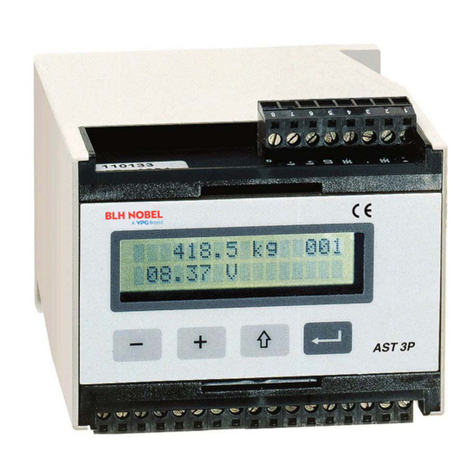
VPG BLH NOBEL PS1010T User manual


NOTICE
BLH Nobel maes no representation or warranties of any ind whatsover with
respects to the contents hereof and specifically disclaims any implied warranties or
merchantability or fitness for any particular purpose. BLH Nobel shall not be held
liable for errors contained herein or for incidental or consequential damages in
connection with the furnishing, performance, or use of this publication or its contents.
BLH Nobel reserves the right to revise this manual at any time and to mae
changes in the contents hereof without obligation to notify any person of such
revision or changes.

Table of Contents
SECTION 1. Introduction........................................................................................................................1
SECTION 2. Description ........................................................................................................................1
SECTION 3. General Specifications ......................................................................................................2
SECTION 4. Installation.........................................................................................................................3
4.1 PS1010T connections...................................................................................................................4
4.2 Mounting........................................................................................................................................4
SECTION 5. Calibration Procedure .......................................................................................................5
5.1 Procedure......................................................................................................................................5
SECTION 6. Field Engineering ..............................................................................................................6

1
SECTION 1. Introduction
The PS1010T DIN Rail transmitter is designed for Web Tension applications. The
transmitter functionality is to condition, amplify, filter and convert the load cell analog
output signal into a calibrated voltage or current analog output signal. The transmitter
provides full isolation between the load cell input signal, analog output signal and supply
voltage.
SECTION 2. Description
The PS1010T transmitter is intended for field mounting close to the system transducers,
thereby reducing installation costs. The transmitter provides the user with a selectable
voltage or current output directly proportional to the load cell input signal. The DC
analog current output supports ‘sourcing’, via an external pull down resistor, current
mode operation only. The transmitter is designed to operate from a single DC power
supply in the range of 20 to 30 V (nominally 24 VDC). The PS1010T unit is easily
configured and calibrated via push-buttons and status LED’s on the front of the panel.
The calibration data are stored in non-volatile microcontroller EEPROM memory. The
transmitter module includes a yellow LED on the front panel to provide visual indication
for the push-buttons when they are pressed. Additionally, a green LED is provided to
indicate the internal power status.

2
SECTION 3. General Specifications
Performance
Full Scale Input 3.0 to +3.0 mV/V full bridge
Dead Load Range ± 100% of full scale input
Calibration Range 0.2 to 2.5 mV/V for nominal output
Linearity 0.01% of full scale output
Common Mode Rejection 120 dB minimum
Common Mode Input ±20% of excitation voltage
Temperature Stability 50 ppm/°C
Response Time <100 ms
Input Impedance >250 Mohms nominal
Environment
Operating Temperature 0 to 55°C (32 to 131°F)
Storage Temperature -25 to 55°C (-13 to 131°F)
Humidity 85% at 55 degrees C
Atmosphere nonflammable and noncorrosive
Transducer Supply
Excitation 10 volts DC (symmetric ±5V)
Gage Resistance 175 -1000 Ohms
Gage Type foil (2-3mV/V), full bridge
Number of load cells two (2) per tension zone
Power Supply
Input 24 VDC, +/-5% @ 125 mA
Range 20 to 30 VDC
Analog Output Signals
Voltage 0-10 VDC @ >2K Ohms
Current 4-20mA @ < 700 Ohms
Galvanically Isolated Yes
Interface Panel indicator or PLC input
Enclosure
Type DIN-Rail mount
Overall Size 45 x 75 x 105 mm L x H x D (1.77 x 2.95 x 4.13 in)
Weight 185 grams (6.5 oz)
Terminals
Approvals
CE conforms to IEC 61326
Operating Conditions
Pollution pollution degree 2
Protection IP20 enclosure
Ordering information The basic Unit part number is PS1010T.
Note: Data and specifications are subject to change without notice.

3
SECTION 4. Installation
Carefully remove the PS1010T unit from its packing. Check that the unit is complete
and undamaged. The transmitter power input and output wiring are inserted at one side
of the unit, while the load cell input wirings are inserted at the other side. Therefore to
prevent noise coupling problems, it is recommended to separate the power and
transmitter output wirings from the load cell signal wirings. Terminals are standard
screw clamp type and accept wide range of wire sizes (14 AWG, max. for big terminals
and 18 AWG, max. for small terminals). There should be provision to ground the cable
shields to local (Mecca) ground, e.g. ground terminal on the DIN rail.
The installation location should be free of vibration. The transmitter should not be
located next to strong electrical fields and should have easy access to the module.
The supply voltage should be protected from a short circuit, via fuse or resettable fuse.
For application, which uses a four-wire load cell cable, two jumpers must be installed
between +SEN to +EXC and between -SEN to –EXC. Figure 1 illustrates the electrical
wiring for the PS1010T transmitter module.
Figure 1. PS1010T Electrical Wiring.
VISHAY BLH 3 EDGEWATER DRIVE, NORWOOD, MA. 02062

4
4.1 PS1010T connections
Load cell connection
Terminal
Description
SHIELD
Load cell cable shield input
-SEN
Negative sense input
-EXC
Negative excitation voltage input
-SIG
Negative output signal
+SIG
Positive output signal
+EXC
Positive excitation voltage input
+SEN
Positive sense input
Power & Analog output connection
Terminal
Description
4-20 mA
4-20 mA current output signal
ISO COM
Isolated common return for current
and voltage output signal
0-10V
0-10V voltage output signal
COM
Supply voltage return
+Vin
Supply input voltage
4.2 Mounting
The PS1010T transmitter has a slotted back panel for standard 35 mm DIN Rail
mounting. Figure 2 shows the PS1010T mechanical dimension.
Figure 2. PS1010T Mechanical Dimensions.

5
SECTION 5. Calibration Procedure
The PS1010T transmitter provides both current and voltage output simultaneously; however
the transmitter can only be calibrated for one output at a time. The zero and full scale
calibration of the transmitter are accomplished via the transmitter front panel ZERO “+”, “-“
and GAIN “+”, “-“ push buttons, and the transmitter status LED. The following procedure is
recommended for proper calibration of the transmitter.
5.1 Procedure
• Connect the PS1010T transmitter as shown in Figure 1.
• Apply power to the transmitter and check for the transmitter’s green LED.
• Connect analog output to voltage or current meter.
• Apply the load cell “zero” input signal and press ZERO “+” or ZERO “-“ until zero
output signal is adjusted. If the signal output is outside normal range and does not
respond to the ZERO buttons, press both buttons GAIN “+” and GAIN “-“
simultaneously to set lowest gain. Continue to adjust zero by pressing ZERO “+” or
ZERO “-“ until the transmitter output signal is adjusted to zero output level.
• Apply the load cell “full-scale” input signal and press GAIN “+” or GAIN “-“ until the
transmitter output signal is adjusted to full-scale output level.
• When transmitter output signals (low and high levels) are satisfied, push
simultaneously the GAIN “+” and ZERO “+” to save the calibration data in non-volatile
memory.
•Calibration is completed. If you want to interrupt the calibration process, do not
perform the save command. You can always recall the last saved calibration data by
pressing simultaneously the GAIN “-“ and ZERO “-“ or power down and up the unit.
Notes:
• Note that every time a calibration push-button is pressed, the yellow LED is turned
on.
• If the push-button is pressed one time, it causes the transmitter output signal to
increment or decrement by small amount. If a large amount of signal change in
output signal is required, then press and hold down the pushbutton accordingly.
• After a dual button command the functionality of the buttons are inhibited for 10
seconds. Release the buttons within this time in order to correctly save or recall
calibration data.
• The end to end gain adjustment time is <1.5 min. At any gain, the time to adjust the
output signal from 0 to 10 V (or 4 to 20 mA) is < 1 min. If the maximum gain is applied
(then <1 min is the time to balance 0.2mV/V referred to input), the time to balance
2mV/V can be up to 10 minutes. To avoid this delay then go to next bullet.
• If the two gain buttons are pushed (GAIN “-“ and “+”), the lowest gain is applied. This
is useful to find the signal and save calibration time.
• If the two zero buttons (Zero “-“ and “+”) are pushed, ‘zero’ balance is achieved at the
unit output (assuming the input is set to 0 V).
Caution: Do not insert sharp or oversized objects into the push-button switch openings as
this may damage the unit. When depressing the push-buttons, use a blunt tipped object and
apply pressure gradually until you see the yellow LED lit up.

6
SECTION 6. Field Engineering
Authorized BLH Field Service Engineers are available around the world to install PS 1010T
based web tension measurement systems and/or train factory personnel to do so. The field
service department at BLH is the most important tool to assure the best performance from
your application. Field service phone numbers are listed below.
Factory: (Main Number)
(781) 298-2000
Canada: (416) 251-2554
or
(800) 567-6098 in Canada


blhnobel.com
Table of contents
Other VPG Transmitter manuals