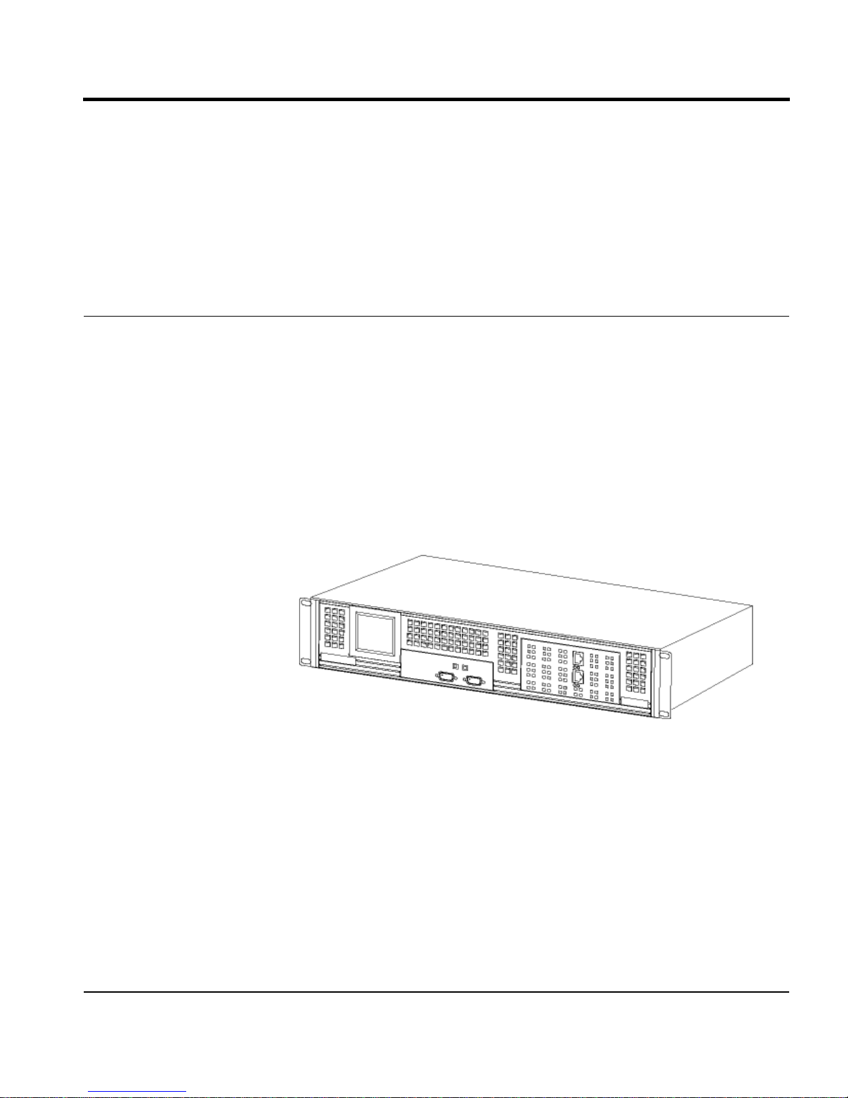
VPNet VSU 5000 User manual

VSU-5000
VPNware Service Unit
User Guide
VPNet Technologies, Inc.

VSU-5000 User Guide
Licenses, Warranties, Copyrights, and Trademarks
THE SPECIFICATIONS REGARDING THE PRODUCTS IN THIS MANUAL ARE SUBJECT TO
CHANGE WITHOUT NOTICE. ALL STATEMENTS, INFORMATION, AND
RECOMMENDATIONS IN THIS MANUAL ARE BELIEVED TO BE ACCURATE BUT ARE
PRESENTED WITHOUT WARRANTY OF ANY KIND, EXPRESS OR IMPLIED. USERS MUST
TAKE FULL RESPONSIBILITY FOR THEIR APPLICATION OF ANY PRODUCTS.
Licenses
Software
VPNet Technologies, Inc. (“VPNet”) and its suppliers grant to Customer (“Customer”) a non-
exclusive and non-transferable license to use VSU VPNos(“Software”) in object code form on a
single VPNware VSU device owned or leased by Customer.
Customer may make one (1) archival copy of the Software provided Customer affixes to such all
copyright, confidentiality and proprietary notices that appear on the original. EXCEPT AS
EXPRESSLY AUTHORIZED ABOVE, CUSTOMER SHALL NOT: COPY, IN WHOLE OR IN
PART, SOFTWARE OR DOCUMENTATION; MODIFY THE SOFTWARE; REVERSE COMPILE
OR REVERSE ASSEMBLE ALL OR ANY PORTION OF THE SOFTWARE; OR RENT, LEASE,
DISTRIBUTE, OR CREATE DERIVATIVE WORKS OF THE SOFTWARE.
Customer agrees that aspects of the licensed materials, including the specific design and structure of
individual programs, constitute trade secrets and/or copyrighted material of VPNet. Customer agrees
not to disclose, provide, or otherwise make available such trade secrets or copyrighted material in any
form to any third party without the prior written consent of VPNet. Customer agrees to implement
reasonable security measures to protect such trade secrets and copyrighted material. Title to Software
and documentation shall remain solely with VPNet.
The license is effective until terminated. Customer may terminate this License at any time by
destroying all copies of Software including any documentation. This License will terminate
immediately without notice from VPNet if Customer must destroy all copies of Software.
Software, including technical data, is subject to U.S. export control laws, including the U.S. Export
Administration Act and its associated regulations, and may be subject to export or import regulations
in other countries. Customer agrees to comply strictly with all such regulations and acknowledges
that it has the responsibility obtain licenses to export, re-export, or import Software.
This License shall be governed by and construed in accordance with the laws of the State of
California, United States of America, as if performed wholly within the state and without giving
effect to the principles of conflict of law. If any portion hereof is found to be void or unenforceable,
the remaining provisions of this License shall remain in full force and effect. This license constitutes
the entire License between the parties with respect to the use of the Software.
Restricted Rights – VPNet’s software is provided to non-DOD agencies with RESTRICTED
RIGHTS and its supporting documentation is provided with LIMITED RIGHTS. Use, duplication, or
disclosure by the Government is subject to the restrictions set forth in subparagraph ‘C’ of the
Commercial Computer Software – Restricted Rights clause at FAR 52.227-19. In the vent the sale is
to a DOD agency, the government’s rights in software, supporting documentation and technical data
are governed by the restrictions in the Technical Data Commercial Items clause DFARS 252.227-
7015 and DFARS 227.7202.

VSU-5000 User Guide
Limited Warranty
Hardware
VPNet Technologies, Inc. (“VPNet”) warrants that for a period of one (1) year from the date of
shipment from VPNet that the Hardware will be free from defects in material and workmanship under
normal use. This limited warranty extends only to Customer as the original purchaser. Customer’s
exclusive remedy and the entire liability of VPNet and its suppliers under this limited warranty will
be, at VPNet or its service center's option, repair or replacement within ten (10) business days or
refund of the Hardware if returned to the party supplying the Hardware to Customer, freight and
insurance prepaid. VPNet replacement parts used in Hardware repair may be new or equivalent to
new.
Restrictions. This warranty does not apply if the product (a) has been altered, except by VPNet (b)
has not been installed, operated, repaired, or maintained in accordance with instructions supplied by
VPNet, (c) has been subjected to abnormal physical or electrical stress, misuse, negligence, or
accident, or (d) is used in ultrahazardous activities.
DISCLAIMER OF WARRANTY. EXCEPT AS SPECIFIED IN THIS WARRANTY, ALL EXPRESS
OR IMPLIED CONDITIONS, REPRESENTATIONS, AND WARRANTIES INCLUDING,
WITHOUT LIMITATION, ANY IMPLIED WARRANTY OF MERCHANTABILITY, FITNESS
FOR A PARTICULAR PURPOSE, NONINFRINGEMENT OR ARISING FROM A COURSE OF
DEALING, USAGE, OR TRADE PRACTICE, ARE HEREBY EXCLUDED TO THE EXTENT
ALLOWED BY APPLICABLE LAW.
IN NO EVENT WILL VPNET OR ITS SUPPLIERS BE LIABLE FOR ANY LOST REVENUE,
PROFIT, OR DATA, OR FOR SPECIAL INDIRECT, CONSEQUENTIAL, INCIDENTAL, OR
PUNITIVE DAMAGES HOWEVER CAUSED AND REGARDLESS OF THE THEORY OF
LIABILITY ARISING OUT OF THE USE OF OR INABILITY TO USE THE PRODUCT EVEN IF
VPNET OR ITS SUPPLIERS HAVE BEEN ADVISED OF THE POSSIBILITY OF SUCH
DAMAGES. In no event shall VPNet's or its suppliers’ liability to Customer, whether in contract, tort
(including negligence), or otherwise, exceed the price paid by Customer. The foregoing limitations
shall apply even if the above-stated warranty fails of its essential purpose.
Software
VPNet warrants that for a period of ninety (90) days from the date of shipment from VPNet: (i) the
media on which the Software is furnished will be free of defects in materials and workmanship under
normal use; and (ii) the Software substantially conforms to its published specifications. Except for the
foregoing, the Software is provided AS IS. This limited warranty extends only to Customer as the
original licensee. Customer’s exclusive remedy and the entire liability of VPNet and its suppliers
under this limited warranty will be, at VPNet or its service center’s option, repair, replacement, or
refund of the Software if reported (or, upon request, returned) to the party supplying the Software to
Customer. In no event does VPNet warrant that the Software is error free or that Customer will be
able to operate the Software without problems or interruptions.
Restrictions. This warranty does not apply if the product (a) has been altered, except by VPNet, (b)
has not been installed, operated, repaired, or maintained in accordance with instructions supplied by
VPNet, (c) has been subjected to abnormal physical or electrical stress, misuse, negligence, or
accident, or (d) is used in ultrahazardous activities.
DISCLAIMER OF WARRANTY. EXCEPT AS SPECIFIED IN THIS WARRANTY, ALL
EXPRESS OR IMPLIED CONDITIONS, REPRESENTATIONS, AND WARRANTIES
INCLUDING, WITHOUT LIMITATION, ANY IMPLIED WARRANTY OF
MERCHANTABILITY, FITNESS FOR A PARTICULAR PURPOSE, NONINFRINGEMENT OR
ARISING FROM A COURSE OF DEALING, USAGE, OR TRADE PRACTICE, ARE HERBY
EXCLUDED TO THE EXTENT ALLOWED BY APPLICABLE LAW.
IN NO EVENT WILL VPNET OR ITS SUPPLIES BE LIABLE FOR ANY LOST REVENUE,
PROFIT, OR DATA, OR FOR SPECIAL INDIRECT, CONSEQUENTIAL, INCIDENTAL, OR
PUNITIVE DAMAGES HOWEVER CAUSED AND REGRADLESS OF THE THEORY OF

VSU-5000 User Guide
LIABILITY ARISING OUT OF THE USE OF OR INABILITY TO USE THE PRODUCT EVEN IF
VPNET OR ITS SUPPLIERS HAVE BEEN ADVISED OF THE POSSIBILITY OF SUCH
DAMAGES. In no event shall VPNet’s or its suppliers’ liability to Customer, whether in contract, tort
(including negligence), or otherwise, exceed the price paid by the Customer. The foregoing
limitations shall apply even if the above-stated warranty fails of its essential purpose.
VPNware, VSU-1200, VSU-1100, VSU-1000, VSU-10, VPNmanager, VPNremote, VPLink, and
VPNet are trade marks belonging to VPNet Technologies, Inc. MD5 Message Digest Algorithm
Copyright RSA Security, Inc. All other product names mentioned in this manual are trademarks or
registered trademarks of their respective manufacturers.
Compliance
The following information is for FCC compliance of Class A devices: This equipment has been tested
and found to comply with the limits for a Class A digital device, pursuant to part 15 of the FCC rules.
These limits are designed to provide reasonable protection against harmful interference when the
equipment is operated in a commercial environment. This equipment generates, uses, and can radiate
radio-frequency energy and, if not installed and used in accordance with the instruction manual, may
cause harmful interference to radio communications. Operation of this equipment in a residential area
is likely to cause harmful interference, in which case users will be required to correct the interference
at their own expense.
BMSI (Chinese Warning Label)
Hardware, including technical data, is subject to U.S. export control laws, including the U.S. Export
Administration Act and its associated regulations, and may be subject to export or import regulations
in other countries. Customer agrees to comply strictly with all such regulations and acknowledges
that it has the responsibility to obtain licenses to export, re-export, or import hardware.
Trademarks
VSU, VPNmanager, VPNremote, VPLink, VPNos, and VPNet are trademarks belonging to VPNet
Technologies, Inc. MD5 Message Digest Algorithm copyright RSA Data Security, Inc. All other
product names mentioned in this manual are trademarks or registered trademarks of their respective
manufacturers.
Copyright
VSU-5000 VPN Service Unit User Guide
Copyright 2001 VPNet Technologies, Inc.
All rights reserved. Printed in USA.
January 2001
P/N 09-0043-02

Table of Contents
Preface Security . . . . . . . . . . . . . . . . . . . . . . . . . . . . . . . . . . . . . . . . . . . . . . . . . . . . . . . . . . i
Performance . . . . . . . . . . . . . . . . . . . . . . . . . . . . . . . . . . . . . . . . . . . . . . . . . . . . . . ii
Plug-and-Play Installation . . . . . . . . . . . . . . . . . . . . . . . . . . . . . . . . . . . . . . . . . . . ii
How This Book Is Organized. . . . . . . . . . . . . . . . . . . . . . . . . . . . . . . . . . . . . . . . . ii
Change History. . . . . . . . . . . . . . . . . . . . . . . . . . . . . . . . . . . . . . . . . . . . . . . . . . . . iii
Product Registration . . . . . . . . . . . . . . . . . . . . . . . . . . . . . . . . . . . . . . . . . . . . . . . iii
Contacting Technical Support . . . . . . . . . . . . . . . . . . . . . . . . . . . . . . . . . . . . . . . . iii
Chapter 1 Preparing for Installation
Safety Recommendations . . . . . . . . . . . . . . . . . . . . . . . . . . . . . . . . . . . . . . . . . . 1-1
General Site Requirements. . . . . . . . . . . . . . . . . . . . . . . . . . . . . . . . . . . . . . . . . . 1-1
Environmental Requirements . . . . . . . . . . . . . . . . . . . . . . . . . . . . . . . . . . . . . . . 1-3
Required Tools . . . . . . . . . . . . . . . . . . . . . . . . . . . . . . . . . . . . . . . . . . . . . . . . . . . 1-3
Required Equipment . . . . . . . . . . . . . . . . . . . . . . . . . . . . . . . . . . . . . . . . . . . . . . 1-4
Chapter 2 Installing the VSU-5000
Physical Installation . . . . . . . . . . . . . . . . . . . . . . . . . . . . . . . . . . . . . . . . . . . . . . . 2-1
Overview of Front Panel . . . . . . . . . . . . . . . . . . . . . . . . . . . . . . . . . . . . . . . . . . . 2-3
Connecting the VSU-5000 to the Network . . . . . . . . . . . . . . . . . . . . . . . . . . . . . 2-5
Chapter 3 Preparing the VSU-5000 for Configuration
Preparation . . . . . . . . . . . . . . . . . . . . . . . . . . . . . . . . . . . . . . . . . . . . . . . . . . . . . . 3-1
Configuration . . . . . . . . . . . . . . . . . . . . . . . . . . . . . . . . . . . . . . . . . . . . . . . . . . . . 3-1
FIPS Mode . . . . . . . . . . . . . . . . . . . . . . . . . . . . . . . . . . . . . . . . . . . . . . . . . . . . . . 3-8
General Firmware Upgrade Information . . . . . . . . . . . . . . . . . . . . . . . . . . . . . . . 3-8

Chapter 4 Troubleshooting
Power Supply. . . . . . . . . . . . . . . . . . . . . . . . . . . . . . . . . . . . . . . . . . . . . . . . . . . . 4-1
Chassis Cooling Fan . . . . . . . . . . . . . . . . . . . . . . . . . . . . . . . . . . . . . . . . . . . . . . 4-3
Ethernet Interface Module. . . . . . . . . . . . . . . . . . . . . . . . . . . . . . . . . . . . . . . . . . 4-4
APPENDIX A Specifications
Physical Specifications . . . . . . . . . . . . . . . . . . . . . . . . . . . . . . . . . . . . . . . . . . . . A-1
Environmental Specifications . . . . . . . . . . . . . . . . . . . . . . . . . . . . . . . . . . . . . . . A-2
Electrical Specifications . . . . . . . . . . . . . . . . . . . . . . . . . . . . . . . . . . . . . . . . . . . A-2
Compliance Specifications . . . . . . . . . . . . . . . . . . . . . . . . . . . . . . . . . . . . . . . . . A-3
Additional Features . . . . . . . . . . . . . . . . . . . . . . . . . . . . . . . . . . . . . . . . . . . . . . . A-4
APPENDIX B 10/100BASE-T UTP Crossover Cable Pinouts
Glossary VSU Acronyms

i
Preface
This user guide provides installation and configuration information for the
VSU-5000 VPNware Service Units.
The VSU-5000 adds compression, encryption, authentication, and key
management to public data links to ensure privacy and integrity of corporate
data, and to enable the efficient and secure operation of virtual private networks
(VPNs). It is designed to perform complex operations, in real time, without
compromising network performance, and in many cases can actually increase
data throughput.
Security
The VSU-5000 provides data stream privacy by employing cryptographic
algorithms and keys powerful enough for the most sensitive business
communications. It supports DES and Triple DES encryption, as well as the
ISAKMP and SKIP key management standards. Using SKIP, the VSU-5000 is
able to change keys frequently during transmission.

ii
VSU-5000 User Guide
Data authenticity is assured by using MD5™or SHA-1 hashing to reject altered
or forged packets. All security mechanisms employed by the VSU-5000 conform
to IPSec standards, in order to provide interoperability and broaden the use of
VPN technology.
Performance
The VSU-5000 supports IP over 10BASE-T or 100BASE-T local area networks
(LAN). Up to 5000 concurrent site-to-site IPSec sessions are supported. When
packets are encrypted and authenticated according to IPSec guidelines, additional
bytes—in the form of IPSec headers—must be added to packets. In many cases,
the additional packet overhead imposes a performance penalty in return for
security. The extra bytes tend to lengthen packets and reduce the throughput
(measured in packets per second). Of even greater impact is the tendency for
packets lengthened by IPSec headers to be fragmented by network routers,
causing further reductions in performance and additional latency. Real-time
compression performed by the VSU-5000 eliminates packet fragmentation and
produces fewer, smaller packets, which can significantly enhance network
throughput and performance.
Plug-and-Play Installation
The VSU-5000 can be placed anywhere in a 10/100BASE-T LAN to provide
VPN functionality. Native support for IP ensures that the VSU-5000
interoperates transparently with the broadest range of intranet and other network
applications.
The graphical VPNmanager™ (available separately) steps network managers
through the setup process and allows them to configure a VPN in minutes. The
VPNmanager also supports extensive facilities for VPN monitoring and
troubleshooting, and for establishing multi-company extranets. The VSU-5000
provides support for the RADIUS protocol, enabling VPNs that support
thousands of remote users and a variety of mechanisms for remote user
authentication.
How This Book Is Organized
Chapter 1, Preparing for Installation, includes safety, environmental, and
equipment requirements, as well as guidance in planning a VSU-5000
installation.

iii
VSU-5000 User Guide
Chapter 2, Installing the VSU-5000, provides VSU rack mounting instructions,
an overview of the back panel, and a procedure for physical installation,
including placement and connection to the network.
Chapter 3, Preparing the VSU-5000 for Configuration, provides instructions for
setting up VSU-5000 addressing and enabling remote connectivity for using the
VPNmanager, VPNet’s VPN network management application.
Appendix A, Specifications, documents physical, environmental, electrical, and
compliance specifications, as well as additional features.
Appendix B, 10/100BASE-T UTP Crossover Cable Pinouts, provides pinouts for
VSU-5000 crossover cabling between the VSU-5000 and Router.
Change History
Product Registration
To register the VSU-5000, navigate to http://www.vpnet.com on the World
Wide Web.
Contacting Technical Support
Technical support is available to registered users of the VSU-5000.
•Voice: 1-888-VPNET-88 (within U.S.) or 408-445-6600 (outside U.S.)
•FAX: 408-404-1414
•Email: [email protected]
•World Wide Web: http://www.vpnet.com
Version Date Changes
09-0043-01 August 2000 Initial Release
09-0043-02 January 2001 Chapter 3 - Modified VSU Quick Setup section,
Added FIPS Mode and General Firmware
Upgrade Imformation

iv
VSU-5000 User Guide

Preparing for Installation 1-1
Chapter 1 Preparing for Installation
This chapter includes safety, environmental, and equipment requirements, as
well as guidance in planning the VSU-5000 installation.
Safety Recommendations
When using the VSU-5000, follow these safety guidelines:
•Keep the chassis area clear and dust-free during and after installation.
•Keep the VSU-5000 ventilation gratings clear of any blockages.
•Do not rest equipment in excess of 10 lbs. on top of the VSU-5000 chassis.
•Disconnect all power before doing the following:
•Changing the Ethernet or serial port connection
•Removing a chassis
•Never assume power is disconnected from a circuit. Always check.
NOTE: The VSU-5000 is enclosed in a tamper-evident case that meets U.S.
NIST FIPS 140-1 Level Physical Security and may be replaced only by an
authorized service technician.
General Site Requirements
This section describes the requirements your site must meet for safe installation
and operation of your system. Ensure that your site is properly prepared before
beginning installation.

1-2 Preparing for Installation
VSU-5000 User Guide
Configuring Equipment Racks
The VSU-5000 can be placed on a desktop or mounted in a rack. The location of
the chassis and the layout of your equipment rack or wiring room are extremely
important for proper system operation. Equipment placed too close together,
inadequate ventilation, and inaccessible panels can cause system malfunctions
and shutdowns, and can make system maintenance difficult.
The following information will help you plan an acceptable equipment rack
configuration.
•Enclosed racks must have adequate ventilation. Ensure that the rack is not
overly congested because each unit generates heat. An enclosed rack should
have louvered sides and a fan to provide cooling air.
•When mounting a chassis in an open rack, ensure that the rack frame does not
block the ventilation grates. If the chassis is installed on slides, check the
position of the chassis when it is seated all the way into the rack.
•In an enclosed rack with a ventilation fan in the top, excessive heat generated
by equipment near the bottom of the rack can be drawn upward and into the
ventilation grates of the equipment above it in the rack. Ensure that you
provide adequate ventilation for equipment at the bottom of the rack.
Power Supply Considerations
Check the power at your site to ensure that you are receiving “clean” power (free
of spikes and noise). Install a power conditioner if necessary.

Preparing for Installation 1-3
VSU-5000 User Guide
Circuit Breaker (15A) Warning
WARNING: This product relies on the building's installation for short-circuit
(overcurrent) protection. Ensure that a fuse or circuit breaker no larger than 120
VAC, 15A U.S. (240 VAC, 10A international) is used on the phase conductor (all
current-carrying conductors).
SELV Circuit Warning
WARNING: The Ethernet 10/100BASE-T, serial, console, and auxiliary ports
contain safety extra-low voltage (SELV) circuits. Do not connect to a telephone
line.
Environmental Requirements
The VSU-5000 is intended for use in a normal office environment. For more
extreme conditions, verify that temperature, humidity, and power conditions
meet the specifications indicated in Table 1-1.
Additional VSU-5000 specifications are included in Appendix A.
Required Tools
The VSU-5000 chassis can be mounted in a standard 19-inch equipment rack.
Rack mounting requires a Phillips-head screwdriver, the VSU rack mount
bracket kit, and four screws to match the rack. (Screws for attaching the
mounting brackets to the chassis are provided.) Instructions for rack mounting
are provided in the section “Rack Mount” on page 2-1.
Table 1-1 Environmental Requirements
Item Operating Specification
Temperature 32-122°F, 0-50°C
Relative Humidity 5-90%, non-condensing
Altitude 0-12,000 feet, 0-3,660 meters
Voltage 100-240 VAC
Input Frequency 50-60 Hz
AC input current 2.5 Amps

1-4 Preparing for Installation
VSU-5000 User Guide
Required Equipment
The VSU-5000 shipping carton contains:
To use the VSU-5000 in a typical VPN application, the customer must supply:
•Routers providing connectivity to a WAN such as the Internet
•An asynchronous ASCII terminal supporting RS-232 or a PC running
terminal emulation software
•Host computers capable of communicating with the routers via a LAN
(e.g. 10/100BASE-T Ethernet)
•10/100BASE-T Ethernet hubs
•CAT 3 or 5 UTP cable to interconnect router, VSU-5000, and hub(s)
Quantity Part Description
1 VSU-5000 VPN Service Unit
1 VSU-5000 VPN Service Unit User Guide
1 UTP Crossover Cable (for connection to a router, switch, or hub)
1 Null Modem Cable (for connection to the VSU Console port)
1 Power cord (110V) or
Power cord (230V)
1 Rack mount kit
4 Rubber feet for desktop installations

Installing the VSU-5000 2-1
Chapter 2 Installing the VSU-5000
This chapter provides instructions for the physical installation of the VSU-5000,
including rack mounting, placement, and connection to the network.
Physical Installation
The VSU-5000 can be placed on a desktop or mounted in a rack.
Desktop
To install on a desktop, allow sufficient depth in the rear for cabling and on the
sides for ventilation flow.
Rack Mount
The VSU-5000 ships with a VSU rack mount bracket kit, which includes two
L-shaped brackets that attach to the sides of the VSU-5000 and to the front of the
rack.

2-2 Installing the VSU-5000
VSU-5000 User Guide
To attach the VSU-5000 to a standard 19-inch equipment rack:
1. From one side of the VSU-5000, remove the two front side screws
(Figure 2-1).
Figure 2-1 Removing the Rack Mount Screws
2. Using the flat-head screws provided with the bracket, attach the backet to the
VSU-5000 (Figure 2-2).
Figure 2-2 Attaching the Rack Mount Backets
3. Repeat bracket installation on the other side of the VSU-5000.
4. Install the VSU-5000 into a standard 19-inch rack, using screws that fit the
rack (not provided).

Installing the VSU-5000 2-3
VSU-5000 User Guide
Overview of Front Panel
Figure 2-3 show the front panel view of the VSU-5000.
Figure 2-3 Front Panel of the VSU-5000
Console and Auxiliary Ports
The auxiliary port on the VSU-5000 is used for factory testing only and has no
function in normal operation.
The console port accepts an RS-232 DB-9 connection from an asynchronous
ASCII terminal or a PC running terminal emulation software. The connection
requires a null modem cable, which is supplied.
The communication settings for a device interfacing with the console port are
provided in Table 2-1.
Public Port Private Port
Ethernet Port
Status Indicators
Console
Port
Aux Port
Status Indicator
Fault Indicator
Table 2-1 Terminal Settings
Parameter Setting
Baud 9600
Data Bits 8
Stop bits 1
Parity None
Flow control Hardware (RTS/CTS)

2-4 Installing the VSU-5000
VSU-5000 User Guide
Public and Private Ports
The Public port provides an interface to the public network, while the Private
port provides an interface to the private network.
The Public and Private ports are Ethernet 10/100BASE-T compliant host ports.
They accept category 3 or 5 UTP cabling terminated in an RJ-45 connector per
IEEE 802.3 requirements for 100/10BASE-T. The Ethernet ports do not provide
a cross-over function and thus expect to be connected via straight through UTP
cables to a 10/100BASE-T hub or switch.
Ethernet Port Status Indicators
The status indication of the four LEDs on the Ethernet card is listed below:
Table 2-2 Ethernet Card LED Indicators
LED Indication
LK10 Lights up = 10 Mbps connection
LK100 Lights up = 100 Mbps connection
FDX Lights up = Full Duplex Mode
ACT Blinks = Transmit/Receive data

Installing the VSU-5000 2-5
VSU-5000 User Guide
Connecting the VSU-5000 to the Network
Figure 2-4 shows a typical network using the VSU-5000.
Figure 2-4 Example of Two VSU-5000 Hardware Installations
Public
Network
DSU/CSU
Router
VSU-5000
Private LAN
Crossover
Cable
DSU/CSU
Router
VSU-5000
Private LAN
Crossover
Cable

2-6 Installing the VSU-5000
VSU-5000 User Guide
1. Connect the gateway router to the VSU-5000.
Using the supplied UTP crossover cable connect one end to the public port on
the VSU-5000. Connect the other end of the UTP crossover cable to the
router’s Ethernet port (Figure 2-5).
Figure 2-5 Attaching a Router to the VSU-5000
2. Connect the VSU-5000 private (unencrypted) port to the LAN hub or switch
using the supplied straight-through cable.
3. Connect an asynchronous ASCII terminal or PC running terminal emulation
software to the VSU-5000.
Connect the female DB-9 connector of the null modem cable to the Console
port on the VSU-5000. Connect the other female DB-9 connector to the
terminal. The terminal’s communications parameters should be set to 9600
baud, 8 data bits, 1 stop bit, no parity, and hardware flow control.
4. Power on the router, and configure if necessary.
5. Power on the VSU-5000 and proceed to Chapter 3, Preparing the VSU-5000
for Configuration.
Connect UTP Crossover Cable between
the VSU-5000 Public Port and the Router Private LAN
Connection
Table of contents
Other VPNet Gateway manuals
Popular Gateway manuals by other brands

DEUTSCHMANN AUTOMATION
DEUTSCHMANN AUTOMATION UNIGATE IC-RS instruction manual

Citrix
Citrix Citrix Access Gateway 4.2 Checklist

Rainforest Automation
Rainforest Automation EAGLE quick start guide

Marmitek
Marmitek Link ME user guide

Inovonics
Inovonics E 4080 Series quick start

CalAmp
CalAmp Phantom II operating manual