VR Avionics TM1 User manual

TM1
operational &
installation
manual
Updated: 21 September 2023
Copyright 2023 by VR vionics

TM1 manual
© 2023 VR Avionics Inc.
All rights reserved.
This manual and the information contained herein is the proprietar data of VR Avionics. No part of this
manual ma be reproduced, copied, transmitted, disseminated or stored in an storage medium, for an
purpose without the express written permission of VR Avionics, Inc. VR Avionics hereb grants permission to
download a single cop of this manual and of an revision to this manual onto a hard drive or other
electronic storage medium to be viewed for personal use, provided that such electronic or printed cop of
this manual or revision must contain the complete text of this cop right notice and provided further that an
unauthorized commercial distribution of this manual or an revision hereto is strictl prohibited. Information
in this document is subject to change without notice. VR Avionics reserves the right to change or improve its
products and to make changes in the content without obligation to notif an person or organization of
such changes. Visit the VR Avionics website (www.vravionics.com) for current updates and supplemental
information concerning the use and operation of this and other VR Avionics products.
VR Avionics
www.vravionics.com
2023-09-21 © 2023 VR Avionics page 2 of 16

TM1 manual
Contents
Introduction.........................................................................................................................................................4
Recommended Steps....................................................................................................................................................................... 4
Operation..............................................................................................................................................................5
Parameters Acquisition.................................................................................................................................................................... 5
Temperatures (T1 thru T3)........................................................................................................................................................ 5
Pressures (P1 thru P3)................................................................................................................................................................. 5
Speeds (N1 and N2).................................................................................................................................................................... 5
Fuel Flow and Count (FF1 and FC1)....................................................................................................................................... 6
Voltage and Amps (V1 and A1)............................................................................................................................................... 6
Discrete Inputs (D1 thru D5).................................................................................................................................................... 6
Parameters Communication.......................................................................................................................................................... 7
CAN Bus Interface Basics........................................................................................................................................................... 7
Information Message #1............................................................................................................................................................ 7
Information Message #2............................................................................................................................................................ 7
Information Message #3............................................................................................................................................................ 8
Human-Machine Interfaces............................................................................................................................................................ 8
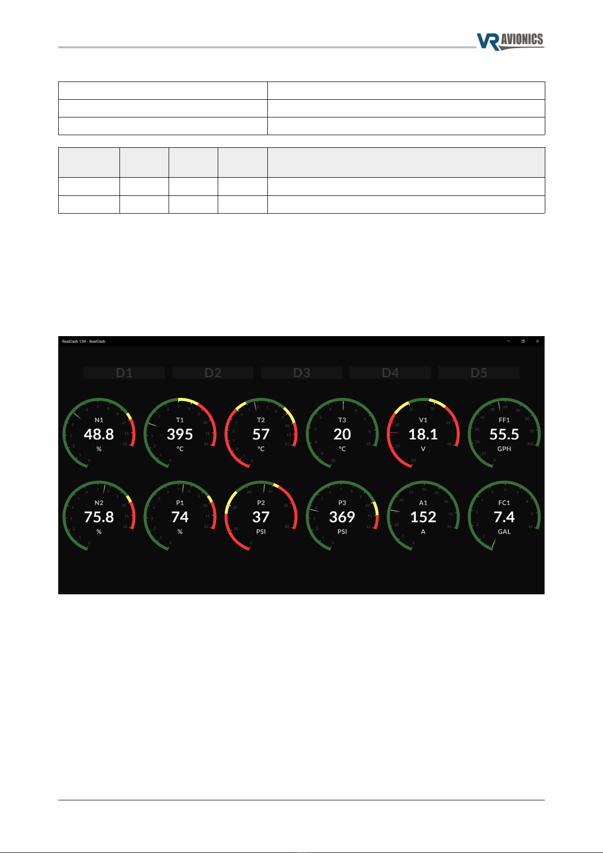
Dashboard Devices...................................................................................................................................................................... 8
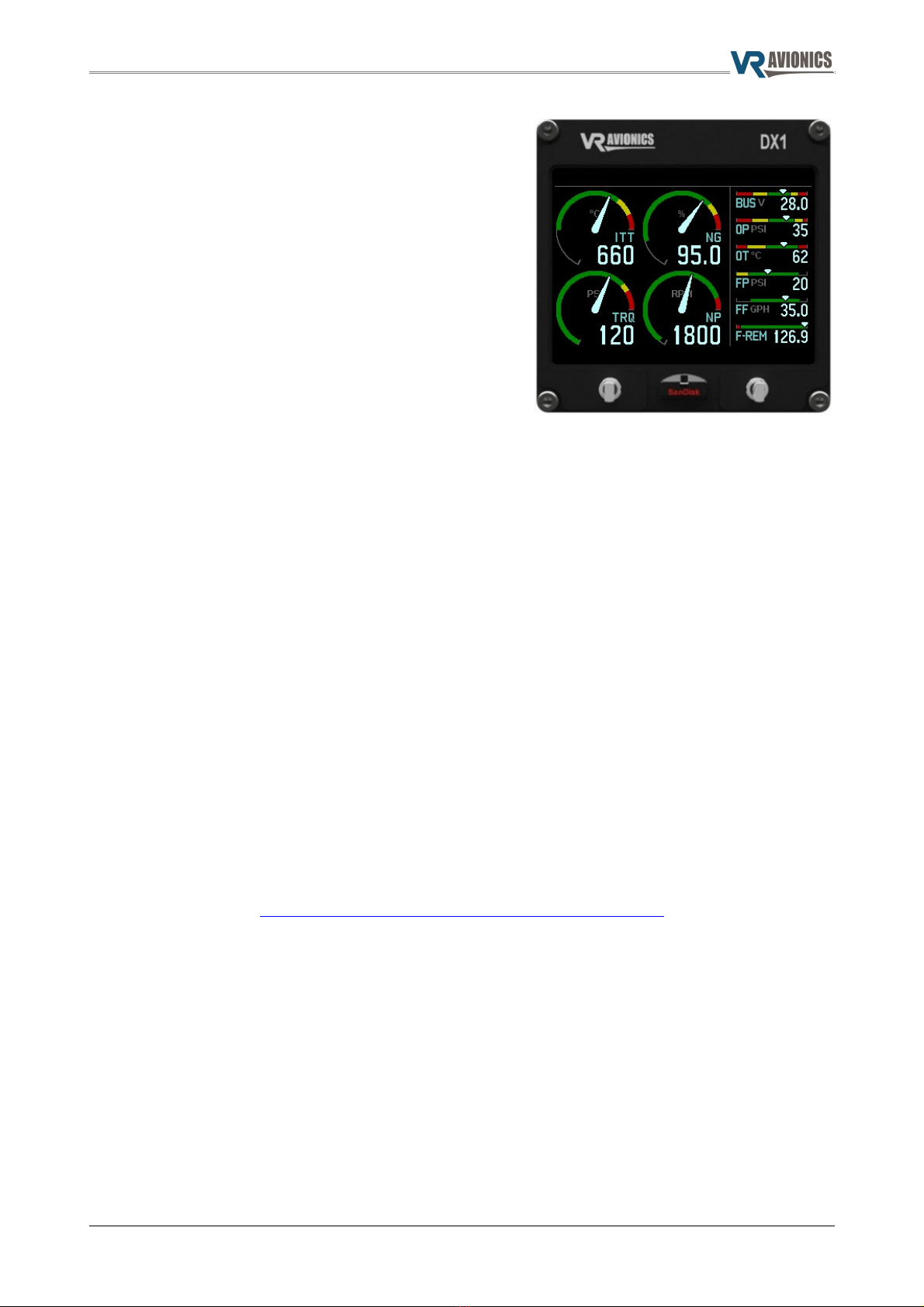
DX1 Displa s.................................................................................................................................................................................. 9
Maintenance Support....................................................................................................................................................................... 9
The SetView App.......................................................................................................................................................................... 9
Installation..........................................................................................................................................................10
Mounting and Wiring.................................................................................................................................................................... 10
Basic Power & Communication.................................................................................................................................................. 10
Temperature Sensing..................................................................................................................................................................... 11
Pressure Sensing.............................................................................................................................................................................. 11
Speed Sensing.................................................................................................................................................................................. 12
Fuel Flow Sensing............................................................................................................................................................................ 12
Voltage and Amps Sensing.......................................................................................................................................................... 12
Discrete Input Sensing................................................................................................................................................................... 13
Sensors / Transducers / Senders / Probes............................................................................................................................. 13
Configuration.....................................................................................................................................................14
Operational Settings...................................................................................................................................................................... 14
CAN Bus Base ID........................................................................................................................................................................ 14
CAN Bus Interface Speed........................................................................................................................................................ 14
N1 & N2 Speed Sensor Full-Scale Frequenc (Hz)........................................................................................................ 15
N1 & N2 Speed Sensor Full-Scale Value........................................................................................................................... 15
FF Fuel Flow Sensor K-Factor................................................................................................................................................. 15
FF Fuel Flow Sensor Full-Scale Value.................................................................................................................................. 15
A1 Current Sensor/Shunt Full-Scale Value....................................................................................................................... 15
A1 Current Zero Deadband Value....................................................................................................................................... 15
P1, P2 & P3 Pressure Sensor Full-Scale Value................................................................................................................. 16
Factor Calibration Settings........................................................................................................................................................ 16
2023-09-21 © 2023 VR Avionics page 3 of 16

TM1 manual
Introduction
Thank ou for choosing the TM1 turbine engine monitor for our aircraft / project. This manual describes the
preparation, operation, installation, configuration, and maintenance of the TM1 line-replaceable unit(s).
Should an thing explained in here be unclear feel free to ask us about it.
Recommended Steps
We recommended the following sequence of actions:
1. Decide on what parameters ou need to monitor and how the should be displa ed. This will
determine whether ou'll need one TM1 or more as well as what additional equipment to get. Use
this manual starting with the chapter on operation to help ou with these decisions.
2. Order the TM1(s) and other parts and perform the installation.
3. Update the TM1's firmware to the latest version (or at least version 1.1).
4. Adjust the TM1 configuration settings to our application requirements. To do so ou will need an
LSI unit and adjust its configuration settings also. To help with this consult our LSI User Guide which
ou can download from our Support web-page. If unsure about something, feel free to email us our
configuration file and we'll help ou get it set up.
5. If ou are using the RealDash dashboard app it needs to be setup. To help with this ou can consult
our LRU RealDas Quick Setup Guide which ou can download from our Support web-page.
6. Perform various operations to verif correct functioning of our engine monitoring s stem. If
possible log operations to an LSI's SD card, anal ze the results ourself through our SetView app,
and should ou need our help simpl email the log files to us.
7. Based on the log files (graphs) if required make new adjustments to configuration settings and
repeat the previous step until satisfied with all aspects of operation.
2023-09-21 © 2023 VR Avionics page 4 of 16

TM1 manual
Operation
The TM1 connects to sensors inside, on and near a turbine engine to acquire and pass along operational
parameters via CAN bus to HMI (human-machine interface) equipment for displa as operator instruments
on DX1 displa s, commercial off-the-shelf dashboard devices, or both.
Parameters Acquisition
The TM1 acquires different operational parameters from reading sensors as follows:
Temperatures (T1 t ru T3)
A single TM1 unit allows for up to three temperature measurements. The most important one is core turbine
temperature, usuall named either ITT or EGT. The T1 channel on the TM1 is reserved for this measurement
as it is designed to measure 0 to 1200º Celsius.
Another important temperature is oil temperature for which we recommend ou use channel T2. On channel
T3 an other temperature such as outside air temperature can measured. These two latter channels are
designed to measure -100 and 411º Celsius.
All temperature measurements are performed through k-t pe thermocouples. For ITT (or EGT) the sensor
comes with (inside) the engine. For other temperatures these ma have to be sourced separatel .
The TM1 communicates temperatures in Celsius. Except for the factor calibration settings, there are no
other user setting related to them. Should Fahrenheit be preferred, this conversion needs to happen at the
HMI (human-machine interface) end.
For exact instructions on temperature sensor installation see the section on temperature sensing. An
unconnected temperature channel (or those where the sensor or one of the sensor wires failed) will read
their respective maximum (1200ºC for T1 and 411ºC for T2 and T3).
Pressures (P1 t ru P3)
A single TM1 unit allows for up to three pressure measurements. Engine torque is an important parameter
t picall derived from one of these. For conformit we recommend ou use P1 for torque. Other important
turbine parameters are oil pressure and fuel pressure for which we recommend P2 and P3 respectivel .
All pressure measurements must be performed through ratiometric pressure sensors. These are the most
commonl available and cost-effective commercial of-the-shelf pressure sensor t pe and does not t picall
come with an engine.
To work correctl the full-scale value (or rating) of the sensor need to be equal to or higher than the
maximum operational value expected to be applied to it. It should not be orders of magnitude higher
though as this could impact measurement accurac .
The parameters derived from different pressure sensors can be communicated in various measurement units.
This can be %, PSI, BAR, KPA, etc. To configure these parameters for particular measurement units as well as
particular full-scale values, see the section on P1, P2 & P3 Pressure Sensor Full-Scale Value.
Though conversions can be done at the HMI (human-machine interface) end, these settings allow them to
be done b the TM1.
For exact instructions on pressure sensor installation see the section on pressure sensing. An unconnected
pressure channels (or those where the sensor or one of the sensor wires broke) will report as zero.
Speeds (N1 and N2)
A single TM1 unit allows for up to two speed measurements. For conformit we recommend ou use N1 for
N1, and N2 for N2, propeller or rotor speed should ou have a split-shaft engine.
All speed measurements are performed through tachometer-generator sensors, which t picall are supplied
with an engine. The can be communicated in different measurement units - %, RPM, etc.
To work as intended the full-scale value (or rating) of the sensor and the frequenc from the tachometer-
generator must be known, and entered into the operational settings for these measurements.
2023-09-21 © 2023 VR Avionics page 5 of 16

TM1 manual
For exact instructions on speed sensor wiring see the installation section on speed sensing. An unconnected
speed channels (or those where the sensor or its sensor wire broke) will read as zero.
Fuel Flow and Count (FF1 and FC1)
A single TM1 unit allows one fuel flow measurement (FF1) accompanied b its fuel counter parameter (FC1).
Fuel flow is measured through a pulse-based fuel flow sensor, which will have to be sourced separatel . Fuel
flow can be communicated in different measurement units - GPH, LPH, PPH, etc.
To work properl the k-factor of the sensor as well as the expected full-scale flow-rate in terms of the
desired fuel quantit units (gallons, liters, pounds, etc) must be known, and correctl configured into the
operational settings.
For exact instructions on speed sensor wiring see the installation section on fuel flow sensing. If unconnected
(or the sensor or its wiring fails) then FF1 will read as zero, and FC1 will no longer count the fuel used.
Voltage and Amps (V1 and A1)
A single TM1 unit allows for one voltage and one amps (electrical current) measurement.
The amps measurement is performed through a current measurement shunt. These are commonl available
commercial of-the-shelf sensors and will have to be sourced separatel .
The voltage measurement simpl senses one side of the shunt to report a voltage between 0 and 50V to the
nearest 0.1 volt resolution.
For the amps measurement to work properl the rating or full-scale value of the shunt/sensor need to be
equal to or higher than the maximum operational value expected to be applied to it. Do not make it too
much higher though, since this can impact measurement accurac .
The amps parameter is communicated in the desired amps resolution. Except for the factor calibration
settings, there are operational settings for it. Though conversions can be done at the HMI (human-machine
interface) end, these settings allow them to be done b the TM1.
For exact instructions on shunt/sensor wiring see installation section on voltage and amps sensing. If
unconnected (or the sensor or its wiring fails) then one or both parameters ma read as zero.
Discrete Inputs (D1 t ru D5)
A single TM1 unit allows up to five discrete measurements on inputs D1 to D5.
Each discrete parameter reports one of three states – FLOAT, HIGH, or LOW. It reports FLOAT when its input
is open circuit, HIGH if a voltage above 2.5V is applied to it, and LOW if the applied voltage is below 1V.
For instructions on discrete input wiring see installation section on discrete input sensing.
2023-09-21 © 2023 VR Avionics page 6 of 16

TM1 manual
Parameters Communication
The TM1 communicates acquired parameters (described in the previous section) via Standard Frame
messages via its CAN bus interface as described in this section.
CAN Bus Interface Basics
Nominal bit time / rate Determined b the setting ”CAN Bus Interface Speed”
Frame format / identifier bit length Base frame format / 11 identifier bits
Information Message #1
Information message #1 identifier CAN Bus Base ID + 0
Information message #1 length 8 (b tes)
Information message #1 send rate 10 messages per second
Parameter Size
(bits)
Index
(bits)
Value
Offset
Details
N1 12 0 0 N1 speed parameter.
N2 12 12 0 N2 speed parameter.
T1 11 24 0 T1 temperature parameter in degrees Celsius from 0 to 1200.
T2 9 35 -100 T2 temperature parameter in degrees Celsius from -100 to 411.
P1 10 44 0 P1 pressure parameter.
P2 10 54 0 P2 pressure parameter.
Information Message #2
Information message #1 identifier CAN Bus Base ID + 1
Information message #1 length 8 (b tes)
Information message #1 send rate 10 messages per second
Parameter Size
(bits)
Address
(bits)
Value
Offset
Details
FF1 12 0 0 Fuel Flow (rate) parameter.
A1 12 12 0 Amps parameter.
T3 9 24 -100 Temperature 3 parameter in degrees Celsius from -100 to 411.
P3 10 33 0 P3 parameter.
V1 9 43 0 Voltage parameter in 0.1 volts resolution from 0 to 50 volts.
Unused 2 52 - Blank bits = 0
D1 2 54 0 0 = Open, 1 = High, 2 = Low
D2 2 56 0 0 = Open, 1 = High, 2 = Low
D3 2 58 0 0 = Open, 1 = High, 2 = Low
D4 2 60 0 0 = Open, 1 = High, 2 = Low
D5 2 62 0 0 = Open, 1 = High, 2 = Low
2023-09-21 © 2023 VR Avionics page 7 of 16

TM1 manual
Information Message #3
Information message #1 identifier CAN Bus Base ID + 2
Information message #1 length 8 (b tes)
Information message #1 send rate 1 message per second
Parameter Size
(bits)
Address
(bits)
Value
Offset
Details
SN1 14 0 0 Serial number of particular TM1 unit.
FC1 14 14 0 Fuel Counter parameter. Starts at zero after power-up.
Human-Mac ine Interfaces
Das board Devices
Parameters measured b TM1 units can be displa ed on dashboard devices using vehicle companion or
dashboard apps like RealDas (realdash.net). These apps run on various commercial off-the-shelf devices on
top of all the main operating s stems. Below is an example of a custom dash panel ou can construct.
To transfer the parameters from CAN bus to the dashboard device ou can use an LSI unit from us or an
similar device from another vendor that is supported b the dashboard app. Since the CAN bus messages
can be shared with multiple devices simultaneousl , this allows the use of multiple different devices.
Note that at least one LSI is required to perform support tasks through our SetView app. This LSI can
however also be used to transfer data to a dashboard device as support tasks onl require temporar access
to this LSI. After such tasks, the dashboard device can be plugged back into the LSI for normal operation.
For more on the LSI, how it works and how to configure it, consult the LSI User Guide which ou can
download from our website.
To get ou started quickl with the TM1 and RealDash, see the LRU RealDas Quick Setup Guide which ou
can download from our Support web-page.
2023-09-21 © 2023 VR Avionics page 8 of 16

TM1 manual
DX1 Displays
The TM1 units can also work with one or more of our DX1
displa s to provide operator instrumentation as shown to
the right which can mount onto an instrument panel.
It has a persistent annunciation bar at the top across all
pages and these can be linked to TM1 discrete parameters.
On the engine page (shown) it has space for 4 primar
needle gauges on the left, as well as up to 6 secondar
slider gauges to the right, which can be scrolled through or
set to automaticall scan through ever 10 seconds.
Maintenance Support
The TM1 works with an LSI to allow maintenance and support tasks to be performed. These tasks are a must
to configure the TM1, update its firmware, and helps to validate operation.
The LSI connects via USB cable to a laptop PC that runs our SetView app.
For instructions to install maintenance support see installation of basic power & communication.
T e SetView App
SetView is a free Windows application that ou can download from our website. It comes bundled with the
latest firmware for all VR Avionics LRUs, including the TM1, SGC, TSLM, PDC, FSM, and LSI.
Through SetView all maintenance support tasks can be performed on an LRU including:
•Viewing s stem parameters in real-time (and recording them to file),
•Performing diagnostic tests to troubleshoot the s stem,
•Adjusting configuration settings, and
•Updating s stem firmware.
•Viewing log files recorded on an LSI's SD card.
Download it b the following direct link:
ttp://www.vravionics.com/support/ ow-to/#sv-install
You can learn how to perform the various tasks SetView offers ou from our Support web-page.
2023-09-21 © 2023 VR Avionics page 9 of 16

TM1 manual
Installation
Mounting and Wiring
The TM1 unit should be ph sicall mounted close to the engine compartment without exposing it to
excessive heat. Wires that could be subjected to noise will thus be shorter rather than longer.
We recommend in general the use of 20-24 gauge aircraft grade Teflon or Tefzel insulated wire for all wiring
to and from the TM1 unit. We also recommend ou use machined contacts (such as 205090-1) with a crimp
connector housing (such as 5205207-1) and a connector hood (such as 5207908-7).
To crimp these machined contacts, ou can use the AFM8 crimp tool and K13-1 positioner from DMC,
alternativel , the PA1440 crimp tool from Paladin, or similar tools.
Ensure ou use the correct splicing techniques to properl insulate an exposed wire, route and strain-relieve
all wires so the will not chafe against an other object, and secure all connections. Since improper wiring
ma cause damage to the TM1 or aircraft, we recommend ou confirm all wire connections are correct
before turning on an power.
Basic Power & Communication
The diagram below shows how to connect the TM1 to power (10 – 30VDC) and a CAN bus communication
network with other devices including at least one LSI.
The Windows laptop or PC shown onl needs to be connected when ou are configuring settings or
updating firmware. Afterwards it can be unplugged (if it is not also doubling as our dashboard device) and
the USB cable to the LSI can then be reattached to our normal dashboard device.
The 120 Ohm termination resistors should be positioned at opposite ends of the CAN bus cable. The devices
that share the CAN bus must be grounded at a common grounding point.
We recommend using two core cable, one for CAN-H and one for CAN-L.
2023-09-21 © 2023 VR Avionics page 10 of 16

TM1 manual
Temperature Sensing
Install k-t pe thermocouple sensors as ma be required b our application as shown in the diagram below
to acquire the temperature parameter measurements T1, T2, and T3. If a particular measurement is not
required ou can leave their input pins open (unconnected).
K-t pe thermocouple cable must be used to connect the sensors to the TM1. The usuall come within
ellow sheaths enclosing two metal wires, one Chromel (positive) and the other Alumel (negative). The
t pical color coding of the two wires are as follows:
Conductive Material Polarity Color Code
Chromel + Positive Yellow
Alumel - Negative Red
We recommend the use of steel braided thermocouple cables in front of the engine firewall.
Pressure Sensing
Install ratiometric (0.5-4.5VDC) pressure sensors as ma be required b our application as shown in the
diagram below to acquire the pressure parameter measurements P1, P2, and P3. If a particular measurement
is not required ou can leave their respective input pin(s) open (unconnected).
There are hundreds of
The PPR pin provides 5VDC nominal power and reference to all three sensors. We recommend doing the
necessar splice as close to the TM1 unit as possible and then running separate wires to each sensor along
with their respective signal wires as shown. To further improve accurac we recommend running separate
ground wires from each sensor to the common grounding point shared b the TM1 unit.
We recommend the use of shielded cabling particularl in applications subject to significant noise (EMI).
2023-09-21 © 2023 VR Avionics page 11 of 16

TM1 manual
Speed Sensing
Install wires from tachometer-generator sensors to the TM1 as shown in the diagram below to acquire the
speed parameter measurements N1 and N2. If a particular measurement is not required ou can leave their
input pin(s) open (unconnected).
Tachometer-generator sensors are t picall specific to our engine make and model. As such ou need to
consult its manual for electrical connector specifics, for example which pin to ground.
Fuel Flow Sensing
Install a fuel flow sensor as ma be required b our application as shown in the diagram below to acquire
the fuel flow (rate) and fuel count (fuel used) parameters FF1 and FC1. If these are not required ou can leave
the pins shown below open (unconnected).
The FFPR pin provides 12VDC nominal power to the sensor. The TM1 also has a 4.7K ohm pull-up resistor on
its FF1 pin that will accept an compatible pulse-based flow sensor.
Follow the sensor manufacturer's instructions on mechanical mounting and integration into our fuel s stem
as well as an electrical recommendations.
Voltage and Amps Sensing
Install a current measurement shunt/sensor as ma be required b our application as shown in the diagram
below to acquire the amps and voltage parameters A1 and V1. If none of these are required ou can leave all
the pins shown below open (unconnected). If onl voltage is required then no shunt is necessar , and onl
the V1/A1- pin has to be connected to the node that must be measured.
We recommend the use of shielded cabling particularl in applications subject to significant noise (EMI).
2023-09-21 © 2023 VR Avionics page 12 of 16

TM1 manual
Discrete Input Sensing
Install wires from various electrical switches and nodes to the TM1 as ma be required b our application as
shown in the diagram below to acquire discrete input parameters D1 to D5. If an of these are not required
ou can leave their pin(s) shown below open (unconnected).
Each TM1 pin will differentiate between being floating (open), powered high, and grounded. Emplo them
accordingl .
Sensors / Transducers / Senders / Probes
The TM1 allows for literall hundreds if not thousands of possible sensors from a variet of manufacturers,
suppliers, mounting methods, and other specifications. In this manual the are referred to as sensors, but
the are also sometimes referred to as transducers, senders, and probes.
If ou are new to sourcing such sensors, we recommend starting with online part suppl stores such as:
•Aircraft Spruce & Specialt Co. (aircraftspruce.com)
•UMA Instruments (umainstruments.com)
•Electronics International (ifl ei.com)
•Auber Instruments (auberins.com)
•Mouser (mouser.com)
•Digike (digike .com)
2023-09-21 © 2023 VR Avionics page 13 of 16

TM1 manual
Configuration
To set the TM1 up for our application, we recommend the following:
✔Get to know and understand all the configuration settings described in this chapter.
✔Before doing an engine c cle, if ou know an setting's value or can determine it as described here,
do so, else leave it at its factor default as provided here.
✔Do a recorded engine c cle, anal ze the recording, make adjustments, and repeat until satisfied.
✔Feel free to contact us for advice, suggestions or onl for confirmation.
You can view and alter TM1 configuration settings b connecting a Windows laptop or PC for support tasks
and using our free SetView app.
Operational Settings
Configuration Setting Minimum Maximum Factory
CAN Bus Base ID 0 2047 1536
CAN Bus Interface Speed 125K 1000K 142.8K
N1 Speed Sensor Full-Scale Frequenc (Hz) 50.00 10000.00 70.00
N1 Speed Sensor Full-Scale Value 1 4000 1000
N2 Speed Sensor Full-Scale Frequenc (Hz) 50.00 10000.00 70.00
N2 Speed Sensor Full-Scale Value 1 4000 1000
FF Fuel Flow Sensor K-Factor (pulses per liter/gallon/pound) 10.00 10000.00 1200.00
FF Fuel Flow Sensor Full-Scale Value (liter/gallon/pound per hour) 1 400 100
A1 Current Sensor/Shunt Full-Scale Value 0 8000 500
A1 Current Zero Deadband Value 0 100 0
P1 Pressure Sensor Full-Scale Value 1 2000 1000
P2 Pressure Sensor Full-Scale Value 1 2000 1000
P3 Pressure Sensor Full-Scale Value 1 2000 1000
CAN Bus Base ID
This setting sets the base ID for the standard frame (11 bit) messages the TM1 send via its CAN bus interface.
To communicate and work with an LSI or DX1 the base ID needs to be set as follows:
First Unit 1536
Second Unit 1540
Note ou are free to select an other base ID should ou need it to communicate with other device(s).
CAN Bus Interface Speed
This sets the speed in bits per second (bps) of the TM1's CAN bus interface. Options are as follows:
Setting CAN Bus Speed (bps)
You must configure all devices on the CAN bus to
the same speed to allow them to communicate
with each other.
0 142.8K (default)
1 125K
2 250K
3 500K
4 1000K
2023-09-21 © 2023 VR Avionics page 14 of 16

TM1 manual
N1 & N2 Speed Sensor Full-Scale Frequency (Hz)
These settings determine the frequenc (in Hertz) on the N1 and N2 inputs respectivel that would
constitute full-scale speed. It allows for fine adjustment to the nearest 0.01Hz. In most applications
tachometer-generators run at around 70Hz at their respective full-scale speeds. See also N1 & N2 Speed
Sensor Full-Scale Value discussed next as the are related.
N1 & N2 Speed Sensor Full-Scale Value
These settings set the value the respective N1 and N2 parameters will indicate should the full-scale
frequenc (set b N1 & N2 Speed Sensor Full-Scale Frequenc ) be sensed on the N1 and N2 inputs. An
received frequenc above or below will be scaled accordingl . This setting also determines the resolution (or
decimals) of the respective parameter. For example set this to 1000 to indicate in percentage with a
resolution of 0.1% (as t picall used for N1).
FF Fuel Flow Sensor K-Factor
This setting sets the k-factor the TM1 will use to calculate the FF1 and FC1 parameters from the fuel flow
sensor signal it gets on its FF1 input. For precision it allows for fractional adjustment to the nearest 0.01.
Sensor manufacturers usuall suppl a k-factor in terms of pulses per US gallon. This value can be used
directl , or can be adjusted through a simple calculation for other units such as liters, pounds, etc.
This setting can also adjust the resolution or decimals of these parameters - full gallons, tenths of a gallon,
etc. This simpl involves multipl ing the setting value b 10 or dividing it b 10.
Note that both the FF1 and FC1 parameters will report in the same decimal resolution and fuel quantit
measurement units set b this setting.
FF Fuel Flow Sensor Full-Scale Value
This setting adjusts the fuel flow parameter's accurac and responsiveness to be optimal for our application.
Set this to the full-scale (or maximum operational) reading ou would see for FF1. This setting can be a
rough estimate of what ou expect the maximum flow rate our engine will experience.
A1 Current Sensor/S unt Full-Scale Value
This setting sets the particulars of the current sensing shunt connected to the A1+ and V1/A1- inputs so that
the TM1 will correctl calculate the A1 parameter from the differential voltage between these pins. It sets the
amps value for a 50mV differential voltage. An voltage above (up to 75mV) or below will be scaled
accordingl . Shunt are commonl rated at 50mV. For those that are rated different such as for 60mV, this
value can easil be adapted after a simple calculation. Note that the resolution or decimals for the amps
reading is also determined b this setting.
A1 Current Zero Deadband Value
This setting sets the minimum value the A1 parameter will report according to the differential voltage on the
A1+ and V1/A1- inputs described under A1 Current Sensor/Shunt Full-Scale Value. Should the parameter fall
short of the deadband, the TM1 will hold the A1 parameter at zero.
2023-09-21 © 2023 VR Avionics page 15 of 16

TM1 manual
P1, P2 & P3 Pressure Sensor Full-Scale Value
These settings set the full-scale value the TM1 should report should it sense full-scale signal on its P1, P2,
and P3 inputs.
Each pressure sensor has a rated pressure. This is the pressure where the sensor will output full-scale signal.
This pressure rating can be in different units of pressure (PSI, Bar, KPa, etc.) as provided b the manufacturer.
If this is what ou want the TM1 to report in, simpl enter this for this setting. If ou want it reported in
something else including percentage (for engine torque ma be), ou can calculate the setting from the rated
pressure value.
For example, if ou want P1 to report in 0.1 percentage counts where 128 PSI on a 200 PSI sensor should
equate to 100%, ou can calculate P1 Pressure Sensor Full-Scale Value as follows:
Factory Calibration Settings
Factor Calibration settings are particular to a specific TM1 unit and were originall configured at the factor .
As such the will seldom if ever need adjustment. The are however accessible should re-calibration be
needed and the necessar equipment and time is at hand.
Configuration Setting Minimum Maximum Factory
Factor Calibration: T1 Span 0 255
Unit
specific
Factor Calibration: T1 Zero 0 255
Factor Calibration: T2 Span 0 255
Factor Calibration: T2 Zero 0 255
Factor Calibration: T3 Span 0 255
Factor Calibration: T3 Zero 0 255
Factor Calibration: P1 Span 0 255
Factor Calibration: P1 Zero 0 255
Factor Calibration: P2 Span 0 255
Factor Calibration: P2 Zero 0 255
Factor Calibration: P3 Span 0 255
Factor Calibration: P3 Zero 0 255
Factor Calibration: V1 Span 0 255
Factor Calibration: V1 Zero 0 255
Factor Calibration: A1 Span 0 255
Factor Calibration: A1 Zero 0 255
2023-09-21 © 2023 VR Avionics page 16 of 16
1000×200
128 =1562
Table of contents
Popular Measuring Instrument manuals by other brands

Berner
Berner 169091 Operation manual

Sekonic
Sekonic Litemaster Pro L-478D operating manual

Endress+Hauser
Endress+Hauser Cerabar M PMC51? Cerabar M PMP51 operating instructions

Brodie
Brodie BiRotor Plus Installation & operation manual

Milwaukee
Milwaukee MAX MW160 instruction manual

Mastech
Mastech MS2225A Operation manual