Magnaflux LUXMETER User manual

Operating Manual
LUXMETER
Light meter

CONTENTS
Page
1 Description 1
1.1 Operating elements and display 2
1.2 Description of the functions 2
1.3 Probes 3
2 User instructions and maintenance 4
2.1 Care of the Luxmeter 4
2.2 Indications and error messages 4
2.3 Low battery warning and battery replacement 5
2.4 Storing the Luxmeter 5
3 Technical Data 6
3.1 Luxmeter 6
3.2 Photometric probe 6
3.3 Key data for use in NDT (Non-Destructive Testing) 7
3.4 EC conformity 7
3.5 Disposal 7
This operation manual provides important advice for the safe and eective
handling of the device. The manual must be kept at the place of work and be
accessible to operators and maintenance personnel at all times.
1
1. DESCRIPTION
The portable Luxmeter is fitted with a large LCD display which optimally displays
the measured values. The Luxmeter measres and records illuminance (PHOT) in
units of Lux (lx).
The probes are equipped with an automatic SICRAM detection module, which
stores the data of the factory calibration settings. The unit of measurement selec-
tion is also automatic.
Functions of the Luxmeter include:
MAX Calculates the maximum reading
MIN Calculates the minimum reading
AVG Calculates the average reading
REL Relative measurement
HOLD Freezes the display
Automatic de-activation Automatic turning o; can be disabled
NOTE: The Luxmeter does not measure white light in the UV measurement.

2
1.1 OPERATING ELEMENTS AND DISPLAY 1.2 DESCRIPTION OF THE FUNCTIONS
The Luxmeter keypad consists of single-function keys, except the ON-OFF /
Auto-OFF key that has two functions (see description opposite).
When you press a key, you will hear a short 'beep' as confirmation; a longer 'beep'
will sound if the wrong key is pressed.
The functions of each key are described in detail below.
This key has two functions: ON/OFF and AUTO-OFF
ON/OFF: press to switch the device on and o. Switching on
the device activates all display segments for a few seconds
and starts an auto-test (self-diagnosis), which will detect the
probe connected to the input and set the device to standard measurement mode.
The following is displayed:
1. Probe input, connection 8-pin DIN 45326
2. Battery symbol: displays the battery charge level
3. Function display
4. Secondary display line
5. DATA key: displays the maximum (MAX), the minimum (MIN) and the average
(AVG) value of the current measurements
6. CLR key: resets the maximum, average, and minimum values.
7. HOLD key: freezes the display
8. UNIT key: allows you to specify the unit of measure
9. REL key: activates the relative measuring mode during standard operation;
displays the dierence between the current value and the value saved
10. ON-OFF/AUTO-OFF key: turns the init on and o; when pressed together with
the HOLD key, it disables the AutoPowerO function
11. MAX (maximum value), MIN (minimum value) and AVG (average value) symbols
12. Main display line
13. Symbol and comment line
If no probe is connected when the device is switched on, the "PROB" message is
displayed in the Symbol line for a few seconds, while the "ERR" message is shown
in the central part of the display. If a probe is inserted while the device is turned on,
it will not be detected; you will need to turn the device o and on again with the
probe connected for it to be recognised.
Caution: only replace the probe when the instrument is o.

Pressing the HOLD button freezes the current measurement
update and the "HOLD" message will appear in the upper
left-hand corner of the display. To return to the current mea-
surement, press the key again.
This button also deactivates the auto-o function.
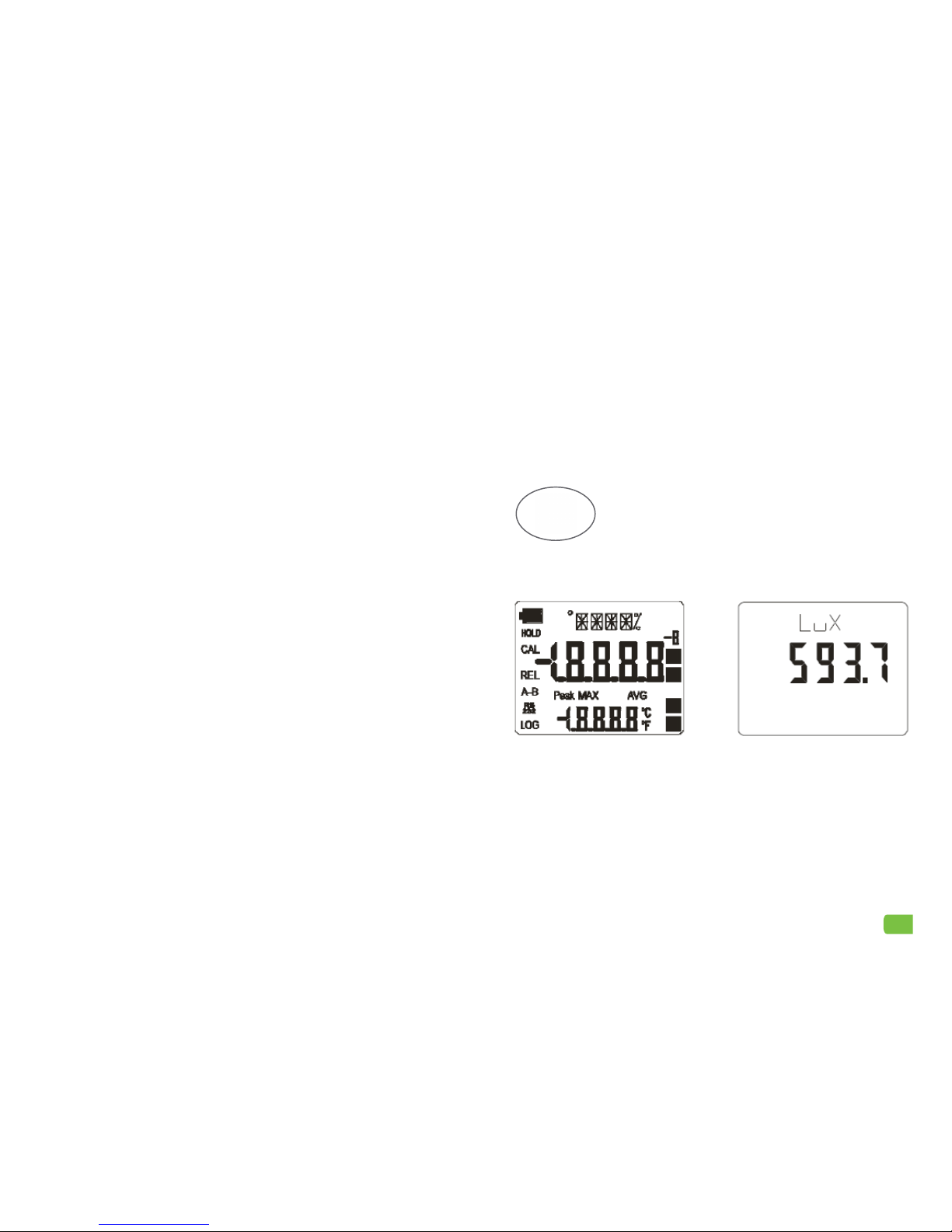
The UNIT button sets the measurement unit of the primary
input. The unit of measurement is displayed in the upper
area of the display, while the measured value is shown on
the middle line. Press the UNIT button repeatedly to set the
desired unit of measure.
NOTE: The available units of measurement are determined by the probe connect-
ed to the input, as shown in the table below:
Type of measurement Unit of Measurement
Illuminance (PHOT) lx – Lux
)
Displays the dierence between the current value and the
value measured when the button was pressed. The indica-
tion "REL" appears on the left side of the display. To return to
the standard measurement, press the key again.
1.3 PROBES
The Luxmeter works with photometric and radiometric probes that measure illumi-
nance (PHOT). All probes are provided with a diuser for cosine correction.
Important: connect the probe before turning on the power. The Luxmeter auto-
matically detects the probe when it is turned on.
The unit of measurement is determined by the probe connected to the input. If
more than one unit of measurement is provided for single probe, press the UNIT
key to select the unit you want.
All probes are factory calibrated and require no further calibration.by the user.
AUTO-OFF: the Luxmeter has a self-o function (AutoPowerO) that automatically
turns the device o after 8 minutes of inactivity (no key is pressed during that time).
To disable this function, press the ON/OFF and HOLD buttons simultaneously.
If you use this function, remember to turn the device o using the ON/OFF key
when you have finished using it. Deactivation of AutoPowerO is indicated on the
display by the flashing battery symbol.
The CLR/ESC key resets the maximum, average and mini-
mum values of the captured measurements.
DATA:
1. Pressing this button once will display the maximum value
(MAX) that the probe will measure. The measured values
are updated each time new samples are etected.
2. Pressing the button a second time displays the minimum value (MIN).
3. Pressing the button a third time displays the average value (AVG).
The detection frequency is once a second.
The unit automatically starts storing the MAX, MIN and AVG values as soon as the unit
is turned on. As long as the device is switched on, the MAX, MIN and AVG values re-
main in the memory, even after exiting the DATA calculation function. These values are
deleted when the device is switched o.
To reset the previous values and start a new measurement session, hold down the CLR
key until the FUNC_CLRD indicator appears.
3
HOLD
+
CLR
DATA
HOLD
UNIT
REL

2. USER INSTRUCTIONS AND MAINTENANCE
This section includes all technical and administrative measures required to main-
tain the meter in proper working condition.
2.1 CARE OF THE LUXMETER
• Do not bend the probe connectors or force them upwards or downwards.
• Do not bend or force the contacts when inserting the probe connector into the
meter.
• The sensors and filters must not exceed the specified temperature limits; the
device may be irreparably damaged.
• Do not drop the probe.
• Avoid taking measurements in direct sunlight, or near high frequency sources,
microwave ovens or strong magnetic fields, as these may influence the results.
• Although the device is water-resitant (IP67 rating), it should not be submerged in
water. The probe connectors must be fitted with sealing gaskets. If the unit does
fall into water. check whether water has penetrated into the device. Handle the
device in such a way as to prevent water infiltration through the connections.
• The housing of the Luxmeter is made of ABS plastic, Do not clean with incom-
patible solvents.
• Do not use or store theLuxmeter in places here it could be exposed to:
-Rapid changes in ambient temperature which may cause condensation.
-Corrosive or combustible gases.
-Direct vibration or shock to the instrument.
• We recommend an annual calibration of the meter unit and the probe.
4
2.2 INDICATIONS AND ERROR MESSAGES
The following table lists all the indications displayed by the Luxmeter during the
dierent operating phases and in the case of a fault:
Display indication Explanation
BATT TOO LOW
CHNG NOW
Indicates insucient battery charge; appears when
you turn the meter on. The meter will issue a long
beep and turn o. Replace the batteries.
CAL
LOST
Program error; appears for a few seconds when the
device is switched on. Contact Magnaflux.
ERR Displays when an already detected probe is discon-
nected from the device. An intermittent 'beep' will
sound at the same time.
FUNC CLRD Indicates that the maximum (MAX), minimum (MIN)
and average (AVG) values have been reset.
NEW_PROB_DET Indicates new probe detected
NO_PRBE_SER_NUM Indicates the serial number of the connected probe
is not available.
OVER Overflow measurement: indicates the probe is mea-
suring a value that exceeds the measurement range.
PLS_EXIT >>> FUNC
RES_FOR_ FACT ONLY
Meaning: please exit by pressing ESC >>> Function
is reserved for factory calibration
PRBE_SER #### #### Displays the serial number of the connected probe.
PROB
ERR
Indicates that a probe with SICRAM module has
been inserted, which is not supported by the meter.
PROB COMM LOST Displays when an already detected probe is discon-
nected from the device. An intermittent 'beep' will
sound at the same time.
SYS
ERR
#
Indicates an Device Management Error. Contact
Magnaflux and ell us the numerical code indicated
on the display.

5
2.3 LOW BATTERY WARNING AND BATTERY REPLACEMENT
The display always shows the battery charge status. As the batteries are depleted, the
symbol "empties". If the charge continues to decrease, the symbol starts flashing. When this
happens, replace the batteries, otherwise correct measurement cannot be guaranteed.
Occasionally the meter may not work properly after replacing the batteries. If this
happens, remove the new batteries and wait a few minutes to allow the circuit
capacitors to discharge completely, then put the batteries back in.
Battery recommendations:
• Remove the batteries when the device is not bering used for a long time.
• Replace flat batteries as soon as possible.
• Dicard leaking batteries
• Always use good quality leakproof alkaline batteries. Inferior batteries are likely
to have an insucient charge capacity.
2.4 STORING THE LUXMETER
Storage conditions:
• Temperature: -25…+65°C.
• Humidity: less than 90%RH without condensation.
Do not store the Luxmeter in a places where it may be exposed to:
• high humidity
• direct sunlight
• high temperatures
• strong vibrations;
• steam, salt or any corrosive gas.
If the battery charge level is insucient, the message below will appear when you turn the
instrument on. The meter ill also issue a long beep and turn o; replace the batteries in order
to turn the instrument back on.
Replacing the batteries:
1. turn o the device
2. unscrew the battery cover counterclockwise
3. replace the batteries (3x 1.5V alkaline batteries - type AA)
4. screw the cover on clockwise

6
3. TECHNICAL DATA
3.1 LUXMETER
Dimensions
(length x width x height) 140 x 88 x 38 mm
Weight 160 g (including batteries)
Material ABS
Display 2 x 4½ digits plus symbols
Visible display area 52 x 42 mm
Operating temperature -5 to +50°C
Storage temperature -25 to +65°C
Relative operating humidity 0 - 90 % RH without condensation
Degree of protection housing IP67
Batteries 3 x 1.5V type AA
Autonomy 200 hours with 1800mAh Alkaline
Power consumption when switched o < 20 μA
Probe input connection 8-pole male connector DIN 45326
Unit of measurement lx – Lux
Part number 134056*
* Kit includes 1 x Luxmeter, 1 x Probe LM-PHOT and 3 x 1.5V alkaline batteries, all
in a case.
3.2 PHOTOMETRIC PROBE
Illuminance measurement probe (PHOT) complete with SICRAM module
Measurement range (Lux) Resolution (Lux)
0.01…199.99 0.01
…1999.9 0.1
…19999 1
…199.99 x 10³ 0.01 x10³
Spectral range in agreement with standard
photopic curve V(λ)
α (temperature coecient) f6(T) <0.05% K
Calibration uncertainty < 4%
f'1 (in agreement with photopic response V(λ)) < 8%
f2 (response according to the cosine rules) < 3%
f3 (linearity) < 1%
f4 (meter reading error) < 0.5%
f5 (fatigue) < 0.5%
Annual drifting < 1%
Operating temperature 0 to 50°C
Reference Standard CIE No 69 – UNI 11142
Note: The probe is not able to detect the white light constituent of UV-A lamps.

3.3 KEY DATA FOR USE IN NDT NONDESTRUCTIVE TESTING
Standard references:
• Magnetic particle inspection: DIN EN ISO 9934 -1
• Penetrant inspection : DIN EN ISO 571-1
• General: DIN EN ISO 3059
Illuminance (PHOT):
• Daylight examination: > 500 lx
• Fluorescent examination: < 20 lx
Note: Do not measure illuminance in direct sunlight; it will produce an incorrect
measurement.
3.4 EC CONFORMITY
Safety EN61000-4-2,
EN61010-1 Level 3
Electrostatic discharge EN61000-4-2 Level 3
Electrodynamic deviation EN61000-4-4 Level 3
Voltage fluctuations EN61000-4-11
Electromagnetic susceptibility to interference IEC1000-4-3
Electromagnetic interference emission EN55020 Class B
3.5 DISPOSAL
Before disposal, ensure that the power supply to the meter is disconnected.
Conform with the local regulations and disposal guidelines.
Rechargeable batteries, dry batteries and button cells are hazardous waste; they
pose risks to health and the environment.
If you have any questions about disposing of this device, contact Magnaflux.
7
Procedure:
1. Decommission the meter
2. Separate the components ccording to type:
• Metals
• Plastic materials
• Composite materials
• Electric and electronic components
3. Dispose all parts according to the local regulations and directions

Bahnhofstr 94-98, 73457 Essingen, Deutschland
Telephone: +49 (0) 7365 81-0 Fax: +49 (0) 7365 81-449
Email: sales.de@magnaflux.com Web: eu.magnaflux.com/de
Faraday Road, South Dorcan Industrial Estate, Swindon, SN3 5HE, UK
Telephone: + 44 (0)1793 524566 Fax: +44 (0)1793 490459
Email: sales.eu@magnaflux.com Web: eu.magnaflux.com
Table of contents
Other Magnaflux Measuring Instrument manuals