VSpeak ECU Konverter Swiwin User manual

ECU converter Swiwin Version: 1.0 www.VSpeak-modell.de Page 1/43
ECU Konverter Swiwin
Manual Version 1.0
Introduction
The VSpeak ECU Converter provides the data of the Swiwin ECU on the telemetry system of
your remote control system.
The ECU Converter calculates the fuel consumption and also transmits it to the respective
transmitter of the model pilot.
Settings of the VSpeak converter can be made directly from the transmitter for Jeti, HoTT and
PowerBox, for all other RC systems with the aid of a Micro SD card.
Always follow the settings for Failsafe (section 1.1 Connection diagram / Failsafe).
The VSpeak ECU Converter can be software-updated by the user.
Supported ECU, Software version:
Testet with:
39 mm
22 mm

ECU converter Swiwin Version: 1.0 www.VSpeak-modell.de Page 2/43
Content Page
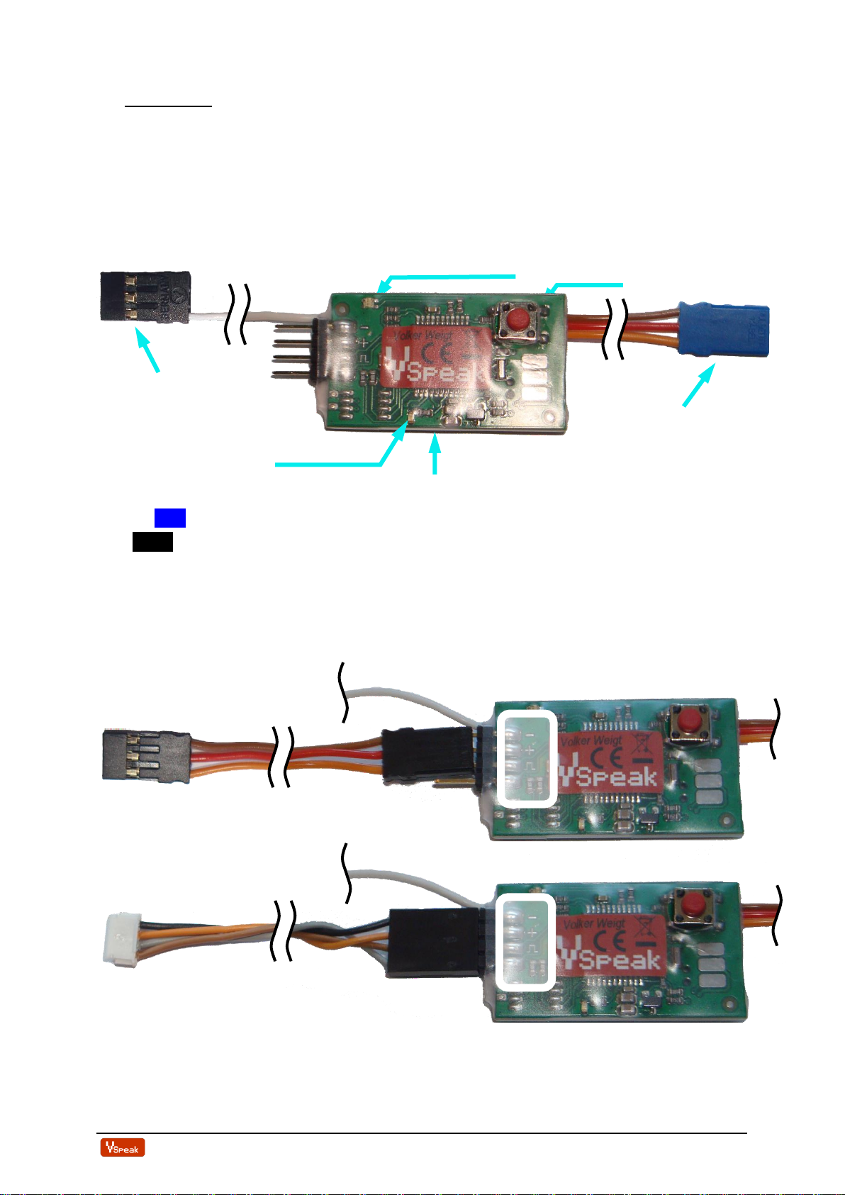
1Hardware....................................................................................................................4
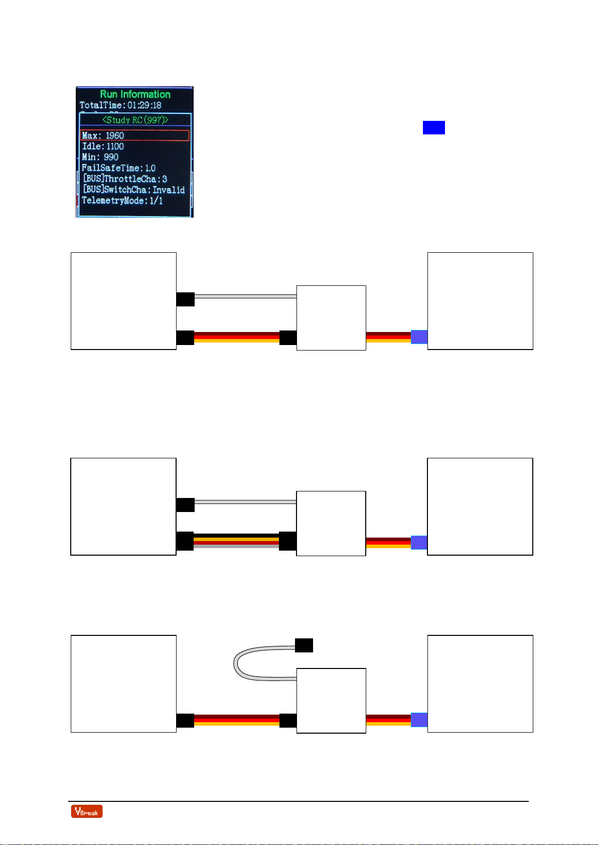
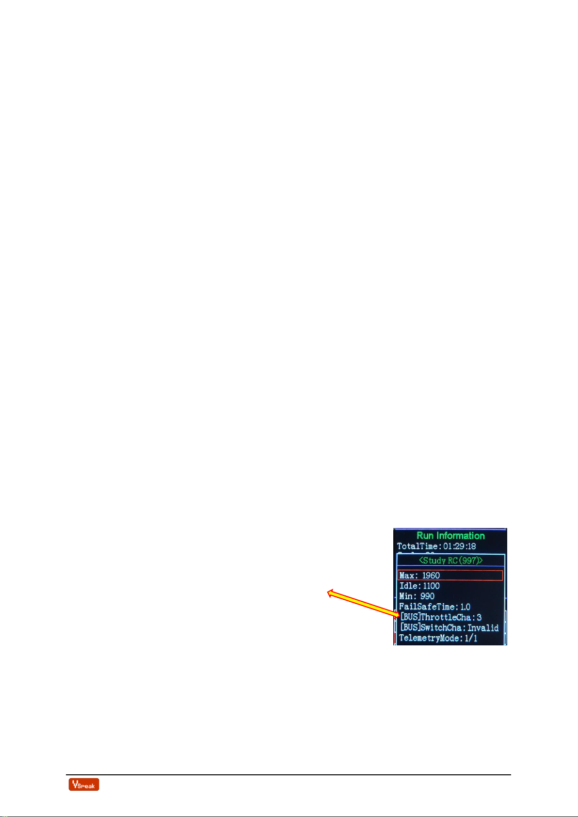
1.1 Connection diagram / Failsafe ..................................................................................5
1.1.1 Jeti Duplex Sensor, Multiplex, HoTT, FrSKY and JR PROPO.................................... 5
1.1.2 Spektrum....................................................................................................................... 5
1.1.3 Jeti EX-Bus, Futaba S.Bus2, Powerbox P²Bus ............................................................ 5
2Telemetry....................................................................................................................6
2.0 Selection of the telemetry system / Parameter file "SWIWIN.TXT" ...................6
2.1 Jeti Duplex EX............................................................................................................9
2.1.1 EX-Daten DC/DS-Sender........................................................................................... 10
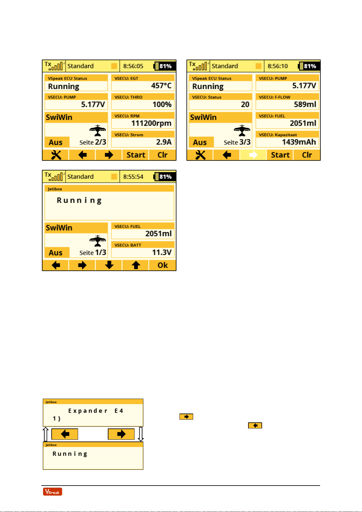
2.1.2 Jetibox........................................................................................................................ 10
2.1.2.1 Expandermenu ..................................................................................................................................... 10
2.1.2.2 Alarms / Parameterization ................................................................................................................... 11
2.1.2.3 Turbine status / Alarms –numerical Values ........................................................................................ 14
2.1.3 Profibox - autonomous telemetry system for Swiwin-ECU........................................ 15
2.2 Multiplex MLink (MSB)..........................................................................................16
2.2.1 Address-Assignment / Alarms .................................................................................... 16
2.2.2 Parameter „SWIWIN.TXT“ ....................................................................................... 16
2.2.3 Turbine status............................................................................................................. 17
2.3 Graupner HoTT.......................................................................................................18
2.3.1 Sensortype.................................................................................................................. 18
2.3.2 Textdisplay................................................................................................................. 18
2.3.2.1 Key assignment .................................................................................................................................... 18
2.3.3 Data-Display/Speech ................................................................................................. 19
2.3.3.1 GAM - General Air Modul................................................................................................................... 19
2.3.3.2 ESC - Electronic Speed Control........................................................................................................... 19
2.3.3.3 VAR –Variometer................................................................................................................................ 20
2.3.4 Parameterization........................................................................................................ 20
2.3.4.1 Alarms.................................................................................................................................................. 21
2.3.4.2 FUEL consumption .............................................................................................................................. 22
2.4 Futaba S.BUS2 .........................................................................................................23
2.4.1 Registration at the transmitter................................................................................... 23
2.4.2 Turbine status –numerical "Current"-Values........................................................... 24
2.4.3 Parameter „SWIWIN.TXT“ ....................................................................................... 25
2.4.4 Alarms........................................................................................................................ 26
2.4.4.1 FUEL low............................................................................................................................................. 26
2.4.4.2 Rotation speed monitoring / RPM low ................................................................................................. 26
2.5 Futaba S.BUS2 V10..................................................................................................27
2.5.1 Registration at the transmitter................................................................................... 27
2.5.2 Assignment JetCat V10 - ECU Values....................................................................... 28
2.5.3 Turbinenstatus –numerische „Strom“-Werte .....Fehler! Textmarke nicht definiert.
2.5.4 Parameter „SWIWIN.TXT“ ...................................................................................... 30
2.5.5 Alarms........................................................................................................................ 30
2.5.5.1 Rotation speed monitoring / RPM low ................................................................................................. 31
2.5.5.2 Battery low / EGT high ........................................................................................................................ 31
2.6 FrSKY S.Port ...........................................................................................................32
2.6.1 LUA script for Taranis............................................................................................... 32
2.6.2 LUA script for Horus (openTX)................................................................................. 32

ECU converter Swiwin Version: 1.0 www.VSpeak-modell.de Page 3/43
2.6.3 Turbine status –numerical „Temperature“-Values.................................................. 33
2.6.4 S.Port ID .................................................................................................................... 34
2.6.5 Parameter „SWIWIN.TXT“ ....................................................................................... 34
2.7 JR PROPO................................................................................................................35
2.7.1 Turbine status –numerical "Current"-Values........................................................... 36
2.7.2 Parameter „SWIWIN.TXT“ ....................................................................................... 37
2.8 PowerBox (P²Bus) ....................................................................................................38
2.8.1 Setup........................................................................................................................... 38
2.8.1.1 FUEL.................................................................................................................................................... 38
2.8.1.2 PRIORITY ............................................................................................................................................ 39
2.8.1.3 SYSTEM ............................................................................................................................................... 39
2.9 Spektrum (X-Bus) ....................................................................................................41
2.9.1 Telemetry display....................................................................................................... 41
2.9.2 Parameter „SWIWIN.TXT“ ....................................................................................... 41
3Technical data ..........................................................................................................42
4EG- Declaration of Conformity ..............................................................................42
5Update.......................................................................................................................43
6Instructions for disposal..........................................................................................43
7Version history .........................................................................................................43
8Contact......................................................................................................................43

ECU converter Swiwin Version: 1.0 www.VSpeak-modell.de Page 4/43
1Hardware
Data LED: green(flashing) →receiving data from the Swiwin ECU and data transfer to the
receiver (at Jeti Sensor only then, if JetiBox buttons are activated)
red (flashing) →no data from ECU–but the connection to the telemetry System
is well
The blue LED is blinking every second to signal the normal function of the ECU Converter.
Use the blue UNI servo plug to connect to the Swiwin ECU pin header labeled TELEMETRY.
The black single-pole UNI servo plug is plugged into the receiver on the throttle channel.
With the Futaba S.Bus2, Jeti EX Bus and Powerbox P²Bus the connection has no function, the
throttle value is transmitted via the respective telemetry bus.
The connection between the VSpeak ECU converter and the remote control system is made
with the 3-pin servo patch cable except in the case of Spektrum, there with the special cable
(see following pictures).
The attachment of the VSpeak ECU converterin the model can be done with velcro tape, double
sided tape or cable ties.
Data LED green/red
Button
to the ECU
TELEMETRY Port
Micro SD card slot (Bottom)
blue LED
To the receiver
Throttle channal
Spektrum XBus connection cable
(Please always indicate when ordering)
3- pin servo patch cable

ECU converter Swiwin Version: 1.0 www.VSpeak-modell.de Page 5/43
1.1 Connection diagram / Failsafe
As can be seen in the following graphics, the VSpeak ECU converter
must be connected between the receiver and the Swiwin ECU. The
throttle signal from the receiver and the telemetry data are
transmitted via the 3-pin servo cable with the blue UNI servo plug.
Set on the ECU:
[BUS]ThrottleCha: 3
TelemetryMode: 1/1
… and the required time for
FailSafeTime:
1.1.1 Jeti Duplex Sensor, Multiplex, HoTT, FrSKY and JR PROPO
For the receiver throttle output Failsafe must be set to no signal. The time until failsafe should
be set to 0 in the remote control system; the FailSafeTime that can be set in the ECU then
applies.
If it is not possible to set "no signal" for FailSafe, then at least Throttle Min should be output
for FailSafe, i.e. -> Turbine Stop (here, of course, set the time until Failsafe in the remote control
system accordingly).
1.1.2 Spektrum
The only difference with Spektrum is the special 4-pin telemetry cable instead of the 3-pin UNI
patch cable - the same applies to FailSafe as described under 1.0.1.
1.1.3 Jeti EX-Bus, Futaba S.Bus2, Powerbox P²Bus
With these systems, the throttle signal is transmitted via the respective telemetry bus, so that
the 1-pin Throttle cable of the VSpeak has no function and is not connected.
Failsafe is transmitted from the telemetry bus to the ECU converter, any settings in the remote
control system have no effect here - only the FailSafeTime in the ECU is effective.
Swiwin
ECU
TELEMETRY
VSpeak
Receiver
Throttle
Telemetry
Swiwin
ECU
TELEMETRY
VSpeak
Receiver
Telemetry
Swiwin
ECU
TELEMETRY
Receiver
Throttle
Telemetry/XBus
VSpeak

ECU converter Swiwin Version: 1.0 www.VSpeak-modell.de Page 6/43
2Telemetry
The voltage for the VSpeak ECU Converter is supplied by the receiver.
The Button of the ECU Converter can be used to switch between the systems Jeti Duplex,
Multiplex, HoTT, Futaba, FrSky, JR PROPO, PowerBox and Spektrum, s. section 2.0.
2.0 Selection of the telemetry system / Parameter file "SWIWIN.TXT"
When you turn on the Telemetry System is signaled by a LED for a period of 3 seconds. While
the blue LED flickers, the STATUS LED shows the chosen telemetry system:
green Jeti Duplex EX (s. section 2.1)
red Multiplex (s. section 2.2)
green (flickering) HoTT (s. section 2.3)
red (flickering) Futaba S.BUS2 (s. section 2.4)
red (flashing) Futaba S.BUS2 V10 (s. section 2.5)
green (flashing) FrSky S.Port (s. section 2.6)
red/green (flashing) JR PROPO (s. section 2.7)
red/red/green (flashing) PowerBox (s. section 2.8)
red Spektrum (s. section 2.9)
Double-click on the Button (similar to the double click of a computer mouse), the telemetry
system can be switched.
To preserve safety during the selection of the telemetry system, the ECU Converter does not
transmit any information until a restart.
The setting is saved.
Parameter file „SWIWIN.TXT“
With the remote control systems Jeti Duplex, HoTT and PowerBox the parameterization can be
done directly at the transmitter, for all other systems the parameter change can be made via the
file „SWIWIN.TXT“.
By inserting an SD card (without file "SWIWIN.TXT") into the Micro SD card slot of the ECU
converter and switching on the converter, the converter recreates the file "SWIWIN.TXT" with
the parameters currently set in the converter. Now you can look at the parameters in the "set
value" column of the "SWIWIN.TXT" file using an editor (Windows Accessories / Editor) and
change the values. The parameters are largely self-explanatory, the permissible value range is
in the "value range" specified. To change the parameters in the ECU converter, the modified
"SWIWIN.TXT" file is now reinserted into the SD card slot and the converter is switched on.
The Data LED green/red signals the status of the Read/Write process of the SD card:
red flashing: Card not readable by the ECU converter
green flashing: Writing / reading the parameter file "SWIWIN.TXT" -> OK
green/red flashing: Parameter transfer of "SWIWIN.TXT" incorrect
With green / red flashing, not all parameter changes have been accepted in the ECU converter,
e.g. because of invalid characters or values outside the range "value range". The ECU converter
then re-created the "SWIWIN.TXT" file with the data currently stored in the converter. You
should look at it again in the editor and compare it with the parameter changes you have in
mind.

ECU converter Swiwin Version: 1.0 www.VSpeak-modell.de Page 7/43
The values in the areas "general" and
"alarms" are applicable for all remote
control systems:
-> global parameters (see next page).
The other sections in the file
"SWIWIN.TXT" are related to the
particular remote control system and
have their meaning only there.
Note Parameter change:
Do not delete lines and do not add any
lines.
Override the parameters instead of
inserting characters.
Only the area "set value" is
authoritative.
Version display
=================================================
***** settings Vspeak ECU converter Swiwin ****
=================================================
set value|value range |unit |description
=================================================
general
-------------------------------------------------
167 |50...600 |ml/min |FuelFlow @ 2.5 V
404 |100...1000 |ml/min |FuelFlow @ 4.0 V
3000 |500...20000 |ml |Fuel tanksize
1 |1,5,10 |ml |FUEL rounded
OFF |OFF,ON | |Taxi Tank
0 |0...30 |% |Throttle offset
1 |1 10 100 1000 |RPM factor
3 |1...16 |Servo |Throttle->ECU
alarms
-------------------------------------------------
800 |OFF,50...2500|ml |FUEL low
6.0 |6.0...12.0 |V |BATTERY low
OFF |OFF,200...600|x100rpm |RPM low
1100 |500...1100 |°C |EGT high
Multiplex Mlink MSB address
-------------------------------------------------
2 |OFF,0...15 |ECU status
3 |OFF,0...15 |FUEL level
4 |OFF,0...15 |BATTERY
5 |OFF,0...15 |RPM
6 |OFF,0...15 |EGT
7 |OFF,0...15 |THROTTLE
8 |OFF,0...15 |PUMP
9 |OFF,0...15 |FUELFLOW
10 |OFF,0...15 |CURRENT
11 |OFF,0...15 |CAPACITY
Futaba - S.BUS2 setting
-------------------------------------------------
3 |1...16 |Servo |Throttle channel
Futaba (using multiple sensors)
-------------------------------------------------
2000 |2000...2100 step10 |Start ID
24 |OFF,1...29 |StBatFl |Slot CURF1678
27 |OFF,1...31 |RPM |Slot SBS01RMO
28 |OFF,1...30 |PumpThr |Slot SBS01V
30 |OFF,1...31 |FuelFlow|Slot SBS01T
31 |OFF,1...31 |EGT |Slot SBS01T
OFF |OFF,ON |EGT/10 |divided by 10
Futaba (using JetCat V10 sensor)
-------------------------------------------------
2200 |2200...2300 step10 |Start ID
8 |1...18 |Slot JetCat V10
Status |Curr., Status|A |Current Value
FrSKY S.Port
-------------------------------------------------
28 |1...28 |Physical ID
1 |1...16 |Group Number
JR PROPO
-------------------------------------------------
ON |OFF,ON |Sensor F-Pack
Status |Curr., Status|A |F-Pack >A<
FUEL |Capa., FUEL |mAh,ml |F-Pack >C<
Battery |Pump, Battery|V |F-Pack >V<
THROTTLE |THRO, F-Flow |%,ml/min|F-Pack >W<
ON |OFF,ON |Sensor TEMP
ON |OFF,ON |Sensor RPM
Spektrum
-------------------------------------------------
OFF |OFF,Curr.,Fuel%,EGT/10|Ampere-Display
=================================================
version 1.0
selected RC system: Jeti Duplex Sensor
=================================================

ECU converter Swiwin Version: 1.0 www.VSpeak-modell.de Page 8/43
Global parameters
general
FuelFlow @2.5V/@4.0V Fuel tanksize
The VSpeak ECU converter can calculate the current FuelFlow and the fuel
consumption on the basis of the ECU pump voltage. The necessary parameters can
be adjusted here, as flow values in ml / min at each 2.5V and 4.0V pump voltage.
Tips for determining the fuel flow rate can be found in the appendix of these
operating instructions.
Fuel tanksize is the capacity of the main tank in ml.
FUEL rounded
The display accuracy of FUEL (ml) can be set here.
Rounding the display makes sense, when using speech to reduce the announcement
syllables.
Taxi Tank
For models where a taxi tank is plugged into the main tank until the model is lifted
off, set "Taxi Tank = ON". If the turbine is in the "Running" status, then when
THROTTLE = 80% is exceeded for the second time, the FUEL will "reset", ie the
displayed FUEL is only once set to "full" (the value set at "Fuel tanksize") again at
this time.
Throttle Offset
The Throttle Offset is used to adapt the throttle display to the RC display on the
Swiwin GSU.
When delivered, this is set to 0%, the entire throttle range is displayed, ...
starting with 0% Min (Stick Min, Trim Low)
over ~10% Idle (Stick Min, Trim Max)
up till 100% Max (Stick Max, Trim Max)
Set the throttle value here as an offset that is displayed when you are idle.
From now on the Min ... Idle area is "hidden", 0 ... 100% then corresponds to Idle ... Max.
RPM factor
The actual turbine speed is the displayed value multiplied by the parameter RPM factor.
Throttle->ECU
Here you can set the servo channel via which the throttle
signal is transmitted from the VSpeak converter to the
ECU.
Throttle->ECU and [BUS]ThrottleCha
must match.
alarms
The parameters are largely self-explanatory, lower values as "low" thresholds and
exceeding of the "high" thresholds trigger alarms, with "OFF" the respective alarm
is deactivated.
The "low..." alarms are activated after at first exceeding the "Low ..." alarm
threshold. The low RPM alarm ends at PUMP = 0.000V, which means that these
alarm is suitable for signaling a turbine flameout.

ECU converter Swiwin Version: 1.0 www.VSpeak-modell.de Page 9/43
2.1 Jeti Duplex EX
The VSpeak ECU converter supports the two Jeti telemetry protocols Jeti EX Sensor and Jeti
EX Bus.
In the delivery condition and after every change of the telemetry system (see section 2.0) the
Jeti EX Sensor is always activated. This means that the VSpeak ECU converter can work with
every Jeti receivers can be connected to the Ext port (this receiver port is always set to
JETIBOX/Sensor on delivery) - otherwise the relevant port would have to be set to
JETIBOX/Sensor or Telemetry Input.
Using the Jetibox (... - emulation in the Jeti DC/DS transmitter) the protocol in the VSpeak
ECU converter can be switched to Jeti EX Bus. The change of the telemetry protocol is only
effective after restarting the VSpeak ECU converter. The EX Bus must also be set on the
relevant Jeti receiver port.
The main differences in the use of the two Jeti protocols are (see section 1.1.3),
that with Jeti EX Bus the throttle channel is also transmitted via EX Bus,
the black, single-pole UNI servo plug (throttle channel) is therefore without function, and
no special Failsafe settings need to be made for the receiver throttle channel
With the Jeti EX Sensor, the connection and the setting of Failsafe are accordingly
section 1.1.1.
The following chapters apply equally to both protocols.

ECU converter Swiwin Version: 1.0 www.VSpeak-modell.de Page 10/43
2.1.1 EX-Daten DC/DS-Sender
(VSECU … VSpeak ECU Converter):
2.1.2 Jetibox
left-button: long pushed return to expander menu
(if ECU converter is shared with other sensors are
connected via an expander)
down-button: Setup ECU converter (s. section 2.1.2.2)
left/right-button: switch between Status/Alarms <-> Sensor values
2.1.2.1 Expandermenu If the VSpeak ECU Converter is connected to an Expander
or Centralbox and the ECU Converter display is activated
with the Right button, the only way back to the
expander menu is pressing the Left button (more
than 3 sec).

ECU converter Swiwin Version: 1.0 www.VSpeak-modell.de Page 11/43
2.1.2.2 Alarms / Parameterization
From the ECU data display, the parameter display can be accessed by pressing the
Down button.
With the Up button the parameter display will left (..to ECU data display). Within the
parameter display you can scroll with the Right button - or - Left button between the
parameter groups "Alarm", "Alarmcode", … and "ECU-EX-Name".
When the desired parameter group is selected, the parameter can be changed by using
Down and Up button.
Value changes are made with the Right button –or- Left button.
Example of parameter selection and parameterization:
Down button
Right button
Down button
Right button (multiple times)
Up button
Up button
Parameter-
group
Parameter
Value range
Step size
Set-Value
(Default)
Alarm
F-RES
OFF, 50 . . . 2500 ml
10 ml
800 ml
BATT
6.0 . . . 12.0 V
0.1 V
6.0 V
RPM
OFF, 20.000 . . . 60.000 rpm
100 rpm
OFF
EGT
500 . . . 1100 °C
5 °C
1100 °C
Alarmcode
FUEL
A, B, C, . . . , X, Y, Z
C
BATT
U
RPM
L
EGT
T
F-Flow /
Pump-V
@ 2.5 V
50 . . . 600 ml/min
1 ml/min
167 ml/min
@ 4.0 V
100 . . . 1000 ml/min
1 ml/min
404 ml/min
FUEL Tank Size
500 . . . 20.000 ml
20 ml
3.000 ml
FUEL rounded
1, 5 , 10 ml
1 ml
Taxi Tank
OFF, ON
OFF
Throttle
Offset
0 . . . 30 %
1 %
0 %
Servo
1 . . . 24
1
1
RPM Factor
1, 10, 100, 1000
1
Jeti Telemetry
Sensor / EX-Bus
Sensor
Jeti-Sensor
EX Name
VSECU, L-ECU, R-ECU, 1LECU, 2RECU
VSECU
*

ECU converter Swiwin Version: 1.0 www.VSpeak-modell.de Page 12/43
Alarms
Irrespective of the possibility to program alarm thresholds for the "EX" values in Jeti
transmitters the VSpeak ECU Converter has the ability to set alarms (by using alarm codes) that
are ECU status depending. These alarms can also be announced by the Profibox as voice
messages.
As can be seen in the table, the alarms for F-RES and RPM can be switched OFF, if no alarm
is to be given at BATT and EGT, the alarm thresholds can be set to "inaccessible" values.
Permanently pending alarms, e.g. FUEL or BATT, max. 3 times repeated.
FUEL
The alarm Fuel is signaled when the fuel rest is lower than the F-RES set value.
BATT
The alarm BATT is signaled when the battery voltage is lower than the BATT set value.
RPM (turbine)
The alarm RPM is signaled when the turbine rotation speed is lower than the RPM threshold
value.
The speed monitoring is started after at first exceeding RPM alarm threshold and ends with
Pump = 0.000V
The RPM alarm is suitable for signaling a "turbine flameout".
EGT
The alarm EGT is signaled if the temperature exceeds the value set at EGT.
F-Flow / Pump-V @ 2.5V respectively 4.0V
FUEL-Flow are the two parameters for the current fuel flow at 2.5V or 4.0V pump voltage.
The two parameters can be determined with the help of a flow meter - or, if you don't have one
at hand, in the following way: You can run the turbine with 2.5 or 4.0V pump voltage for a
period of 1 minute and measure it fuel used. A more precise result can be obtained by carrying
out the measurement over several minutes and dividing the amount of fuel consumed by the
number of minutes (see appendix).
FUEL Tank Size
Volume of the main tank in ml.
FUEL rounded
The display accuracy of FUEL (ml) can be set here.
Rounding the display makes sense, when using speech to reduce the announcement syllables.
Taxi Tank
For models where a taxi tank is plugged into the main tank until the model is lifted off, activate
"Taxi Tank ". With "Tank Size" the tank volume of the main tank has to be set. If the turbine is
in the "Running" status, then when THROTTLE = 80% is exceeded for the second time, the
FUEL will "reset", i.e. the displayed FUEL is only once set to "full" (the value set at "Tank
Size") again at this time.

ECU converter Swiwin Version: 1.0 www.VSpeak-modell.de Page 13/43
Throttle
Offset
The Throttle Offset is used to adapt the throttle display to the RC display on the Swiwin
GSU.
When delivered, this is set to 0%, the entire throttle range is displayed, ...
starting with 0% Min (Stick Min, Trim Low)
over ~10% Idle (Stick Min, Trim Max)
up till 100% Max (Stick Max, Trim Max)
Set the throttle value here as an offset that is displayed when you are idle.
From now on the Min ... Idle area is "hidden", 0 ... 100% then corresponds to Idle ... Max.
Servo (…only Jeti Telemetry "EX-Bus" )
Selection of the Jeti-Servo channel via which the throttle signal is transmitted to the VSpeak
ECU converter via the Jeti EX-Bus.
RPM Factor
The actual turbine speed is the displayed value multiplied by the parameter RPM factor.
Jeti Telemetry
Selection of the Jeti Telemetry protocoll.
Jeti-EX-Sensor-Name
In a 2-turbine model 2 VSpeak ECU converter can be used on Jeti Systems via an expander or
CentralBox. The EX names are:
"1LECU" for Left turbine ECU on input 1and
"2RECU" for Right turbine ECU at the expander input 2.
*

ECU converter Swiwin Version: 1.0 www.VSpeak-modell.de Page 14/43
2.1.2.3 Turbine status / Alarms –numerical Values
The turbines status messages are also displayed numerical values. The assignment is given in
the table.
These status values can be used in Jeti radios, e.g. in logical links, or in LUA-supported radios
for LUA scripts.
Status
Description
21
Restart
20
Running
13
Fuelramp
12
Preheat
11
Ignition
10
Ready
9
TestStarter
8
TestPump
7
TestGasValve
6
TestFuelValve
5
TestGlowPlug
1
Cooling
0
Stop
-1
Time Out
-2
Low Battery
-3
GlowPlug Bad
-4
Pump Anomaly
-5
Starter failure
-6
RPM Low
-7
RPM Instability
-8
High Temp
-9
Low Temp
-10
TempSensorfail
-11
Gas Valve Bad
-12
Fuel Valve Bad
-13
Lost Signal
-14
StarterTemp High
-15
Pump Temp High
-16
Clutch failure
-17
Current overload
-18
Engine Offline
-30
no data

ECU converter Swiwin Version: 1.0 www.VSpeak-modell.de Page 15/43
2.1.3 Profibox - autonomous telemetry system for Swiwin-ECU
Using a Jeti Profibox incl. RSat receiver and the VSpeak ECU converter the telemetry data
from a Swiwin ECU can be transferred completely self-sufficient to the pilot. Not only the
settings using the Profibox can be made, as was shown in the previous chapters - all EX-data
and the important alarms are displayed: EGT, FUEL, ECU battery voltage . . . are given as
voice messages again

ECU converter Swiwin Version: 1.0 www.VSpeak-modell.de Page 16/43
2.2 Multiplex MLink (MSB)
2.2.1 Address-Assignment / Alarms
The VSpeak ECU Converter at delivery uses following addresses:
Swiwin
Adresse
Description
ECU Status Alarm
2
ECU status/alarm message
FUEL Alarm
3
Fuel Level in ml
BATT Alarm
4
Battery voltage in V
RPM Alarm
5
Turbine RPM
EGT Alarm
6
Exhaust Gas Temperature in °C
THROTTLE
7
Throttle Value in %
PUMP
8
Pump voltage in V
FUELFLOW
9
Fuelflow in ml/min
CURRENT
10
Turbine current in A
CAPACITY
11
Capacity of turbine battery in mAh
For the values indicated in the above table with "Alarm", alarm thresholds can be set with the
aid of a Micro SD card and the parameter file "SWIWIN.TXT". Furthermore, the MSB
addresses can be set as desired - a double address assignment within the ECU converter is
excluded.
2.2.2 Parameter „SWIWIN.TXT“
(excerpt)
=================================================
***** settings Vspeak ECU converter Swiwin ****
=================================================
set value|value range |unit |description
=================================================
general
-------------------------------------------------
167 |50...600 |ml/min |FuelFlow @ 2.5 V
404 |100...1000 |ml/min |FuelFlow @ 4.0 V
3000 |500...20000 |ml |Fuel tanksize
1 |1,5,10 |ml |FUEL rounded
OFF |OFF,ON | |Taxi Tank
0 |0...30 |% |Throttle offset
1 |1 10 100 1000 |RPM factor
3 |1...16 |Servo |Throttle->ECU
alarms
-------------------------------------------------
800 |OFF,50...2500|ml |FUEL low
6.0 |6.0...12.0 |V |BATTERY low
OFF |OFF,200...600|x100rpm |RPM low
1100 |500...1100 |°C |EGT high
Multiplex Mlink MSB address
-------------------------------------------------
2 |OFF,0...15 |ECU status
3 |OFF,0...15 |FUEL level
4 |OFF,0...15 |BATTERY
5 |OFF,0...15 |RPM
6 |OFF,0...15 |EGT
7 |OFF,0...15 |THROTTLE
8 |OFF,0...15 |PUMP
9 |OFF,0...15 |FUELFLOW
10 |OFF,0...15 |CURRENT
11 |OFF,0...15 |CAPACITY
Futaba - S.BUS2 setting

ECU converter Swiwin Version: 1.0 www.VSpeak-modell.de Page 17/43
2.2.3 Turbine status
To display the turbine status, texts are stored in the multiplex transmitters as well as in the
"gooseneck" telemetry display.
These do not 1 : 1 correspond to the status messages of the Swiwin ECU.
The assignment is shown in the adjacent table:
Swiwin ECU
Status Text
Restart
RUN...
Running
RUN (reg.)
Fuelramp
acceler.
Preheat
PreHeat1
Ignition
Ignite...
Ready
Stby/START
TestStarter
Manual
TestPump
Manual
TestGasValve
Manual
TestFuelValve
Manual
TestGlowPlug
Manual
Cooling
Cooling
Stop
-OFF-
Time Out
IgnTimOut
Low Battery
BattryLow
GlowPlug Bad
GlowPlug!
Pump Anomaly
WrongPmp
Starter failure
Low-Rpm
RPM Low
Low-Rpm
RPM Instability
Over-Rpm
High Temp
OverTemp
Low Temp
LowTemp
TempSensorfail
TempFail
Gas Valve Bad
FuelFail
Fuel Valve Bad
FuelFail
Lost Signal
FailSafe
StarterTemp High
Low-Rpm
Pump Temp High
WrongPmp
Clutch failure
Acc. Slow
Current overload
PowerFail
Engine Offline
Disabled
no data
-OFF-

ECU converter Swiwin Version: 1.0 www.VSpeak-modell.de Page 18/43
2.3 Graupner HoTT
Using the HoTT System there are 2 ways to transmit telemetry data, on the one hand as "text"
and on the other hand only the pure values.
Using text mode it is possible to establish a bi-directional data transfer, meaning you can use
the keys of the radio or the Smartbox in order to change/enter values in the sensor. Using speech
output is not possible in this mode.
In data-mode the values are only transmitted in a fixed format in one direction. The format is
defined by the sensor type. In this mode it is possible to have speech output for the sensor
values.
2.3.1 Sensortype
The VSpeak ECU Converter for HoTT is a GAM (General Air Modul), a ESC (Electronic
Speed Controller) –or a VAR (Vario). Please select this sensor-type on your radio or Smartbox.
2.3.2 Textdisplay
Using the text-display you can see the current ECU data and you can also change parameters
of the ECU converter.
Change to input
Alarms / parameters
of the ECU converter
(see section 2.3.4)
2.3.2.1 Key assignment
ENTER
ESC
DEC
INC
ENTER
MX-12
MX-16
MC-16
MC-20
MC-32
SET
INC
ESC
DEC
ENTER

ECU converter Swiwin Version: 1.0 www.VSpeak-modell.de Page 19/43
2.3.3 Data-Display/Speech
2.3.3.1 GAM - General Air Modul
"EIN" indicates that the turbine is in the "Running" status.
Since the GAM can only display temperatures up to 235°C, the temperature is divided by 10.
If you see a value of 45°C on the display, you have a "real" temperature of 450 - 459°C.
The fuel level is shown as gauge in % and as numbers in ml. To calculate the percentage of
tank volume value FUEL-Size is 100% fully set when turned on.
2.3.3.2 ESC - Electronic Speed Control
The ESC temperature display is limited to 235 ° C, so the turbine jet temperature is shown
divided by 10, or the other way around: 45 ° C in the display corresponds to 450 ... 459 °C.
The fuel consumption is displayed on the display as capacity value, ie, 2050mAh are 2050ml.
On the other hand, the percentage tank level is displayed as the current, ie, 68.0A correspond
EGT (max)
BATT
FUEL in %
EGT
FUEL
RPM (max)
RPM
PUMP
CAPA (in mAh)
CURR
BATT
Turbinenakku :
Running
FUEL
BATT
EGT
PUMP
RPM
EGT (max)
FUEL in %

ECU converter Swiwin Version: 1.0 www.VSpeak-modell.de Page 20/43
to 68.0% tank level. The tank level is thus easy to read via the associated bar display. To
calculate the percentage of tank volume value FUEL-Size is 100% fully set when turned on.
2.3.3.3 VAR –Variometer
The HoTT Vario offers the possibility to display texts, in the example two lines with an MC20.
The bottom line shows the turbine status or error messages. If the turbine is in the "Running"
status, the lower line shows the EGT and the remaining fuel in ml.
The tank level is converted in a percentage and displayed as altitude, e.g. 68m corresponds to
68% tank level (can be used for the speech output). To calculate the percentage of tank volume
value FUEL-Size is 100% fully set when turned on.
Furthermore, the alarms according to section 2.3.4. are also effective here.
2.3.4 Parameterization The change of sides takes place
with Enter and ESC button of the
SmartBox or with the appropriate
buttons on the HoTT transmitter.
The parameter is selected with
the INC- and DEC-buttons of the
SmartBox
(or the buttons oft he Hott
transmitter) „>“.
With or the value of the
selected parameter is enabled for change
(inverted).
Witht the value can be increased,
with it can be reduced.
Stored is after or
.
SET
INC
SET
DEC
+
DEC
INC
+
DEC
INC
EGT
Status
FUEL
PUMP
w
RPM
ESC
ENTER
DEC
INC
Table of contents
Popular Measuring Instrument manuals by other brands

ChemoMetec
ChemoMetec NucleoCounter NC-250 Instrument User Guide

Atal
Atal AT-VLX-A2-RS-VAV user manual

Hanna Instruments
Hanna Instruments HI 254 instruction manual

UniData Communication Systems
UniData Communication Systems Starflow QSD manual

Union Instruments
Union Instruments PMS3000 Translation of the original operating instructions

ENDEAVOUR
ENDEAVOUR ET0055A user manual