VSV VUB15 Guide

INSTALLATION MANUAL
AND
USER’S GUIDE
UNIVERSAL FILTRATION BLOCKS
VUB15, VUB25 and VUB20/50

2
CONTENTS
Page
1 - GENERAL INFORMATION ……………………………………………………………………………………... 4
Application field ……………………………………………………………………………………………………………………………. 4
Copyrights …………………………………………………………………………………………………………………………………… 4
Protection of environment. Priority tasks of our company ………………………………………………………………… 4
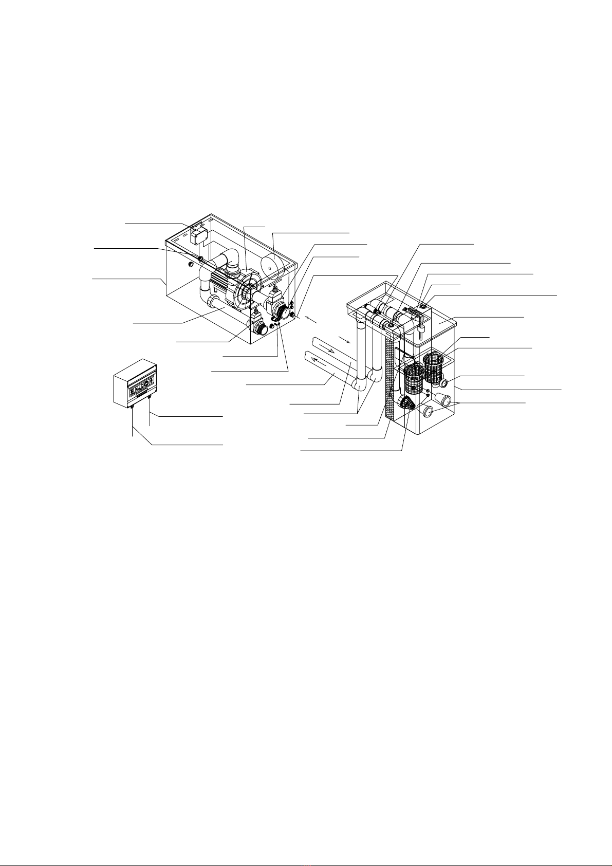
2 - DESCRIPTION OF EQUIPMENT. STANDARD VERSIONS AND THEIR COMPONENT PARTS ….. 5-8
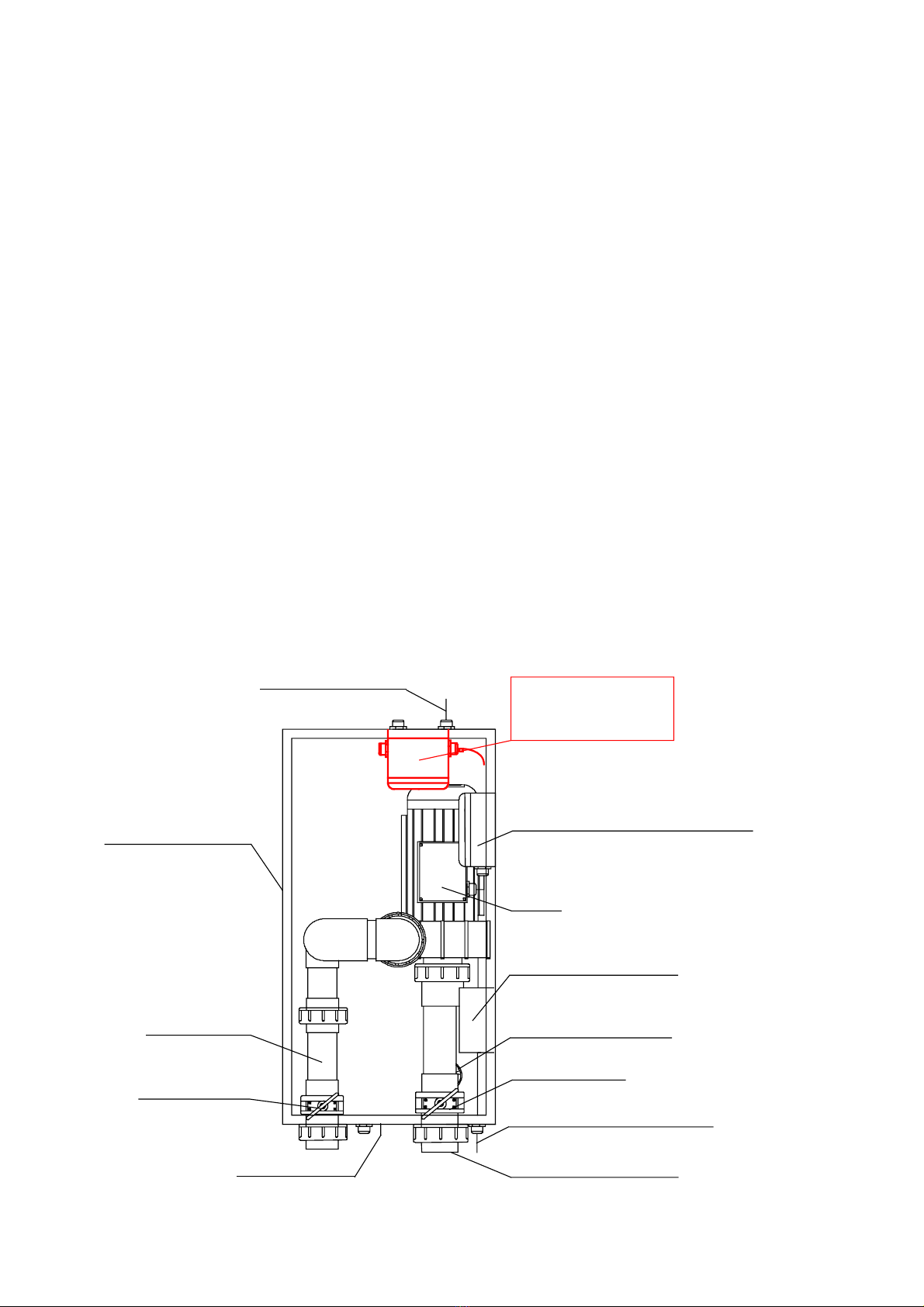
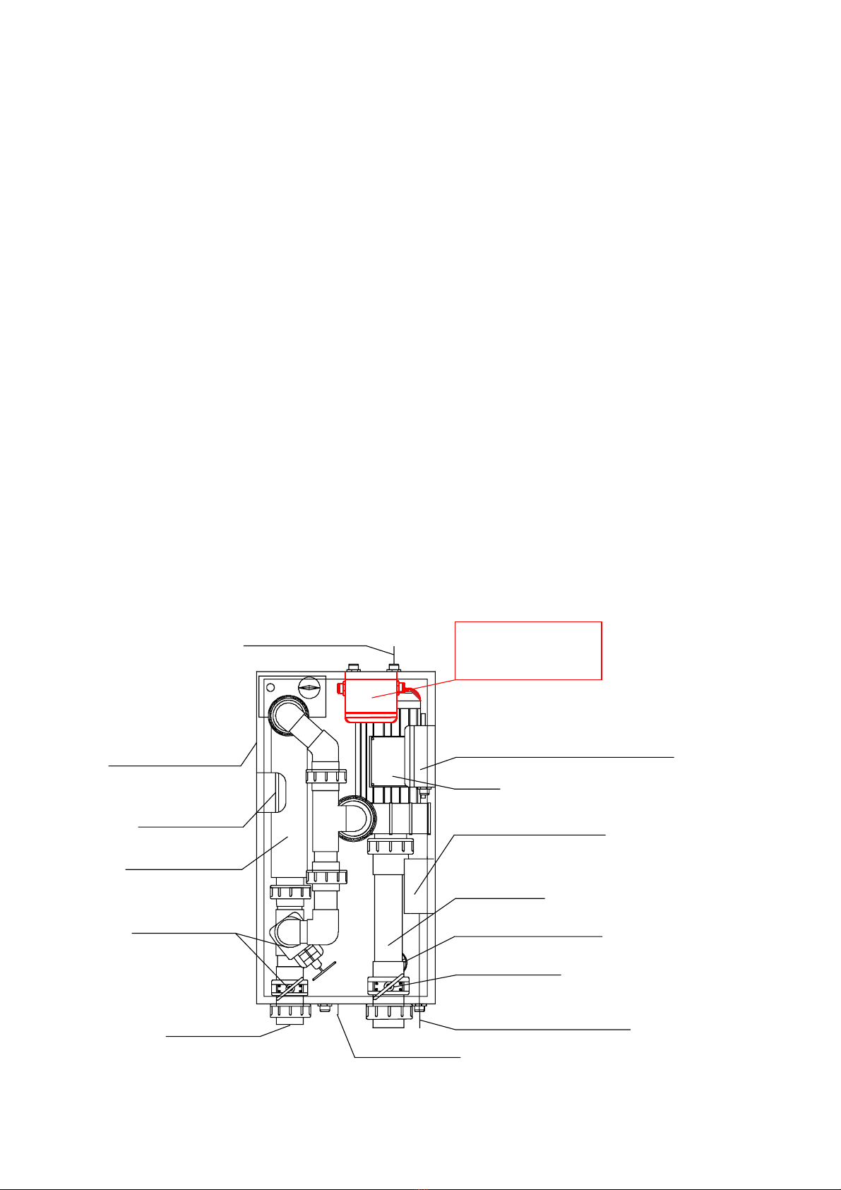
2.1. Principal scheme of universal blocks VUВ……………………………………………………….. 5
2.1/a Block VUВ15 …………………………….…………………………………………………………………………….……….. 6
2.1/b Block VUВ25 …………………………….…………………………………………………………………………….……….. 6
2.1/c Block VUВ20/50 …………………………….…………………………………………………………………………….….. 6
2.1/d Block VUВ15 + heat exchanger ………....…………………………………………………………………………..… 7
2.1/e Block VUВ25 + heat exchanger ………....…………………………………………………………………………..… 7
2.1/f Block VUВ20/50 + heat exchanger ………....………………………………………………………………………… 7
2.1/g Block VUB15 + electric heater ….....……………..……………………………………………………………………. 8
2.1/h Block VUB25 + electric heater ….....……………..……………………………………………………………………. 8
2.1/i Block VUB25 + electric heater ….....……………..…………………………………………………………………….. 8
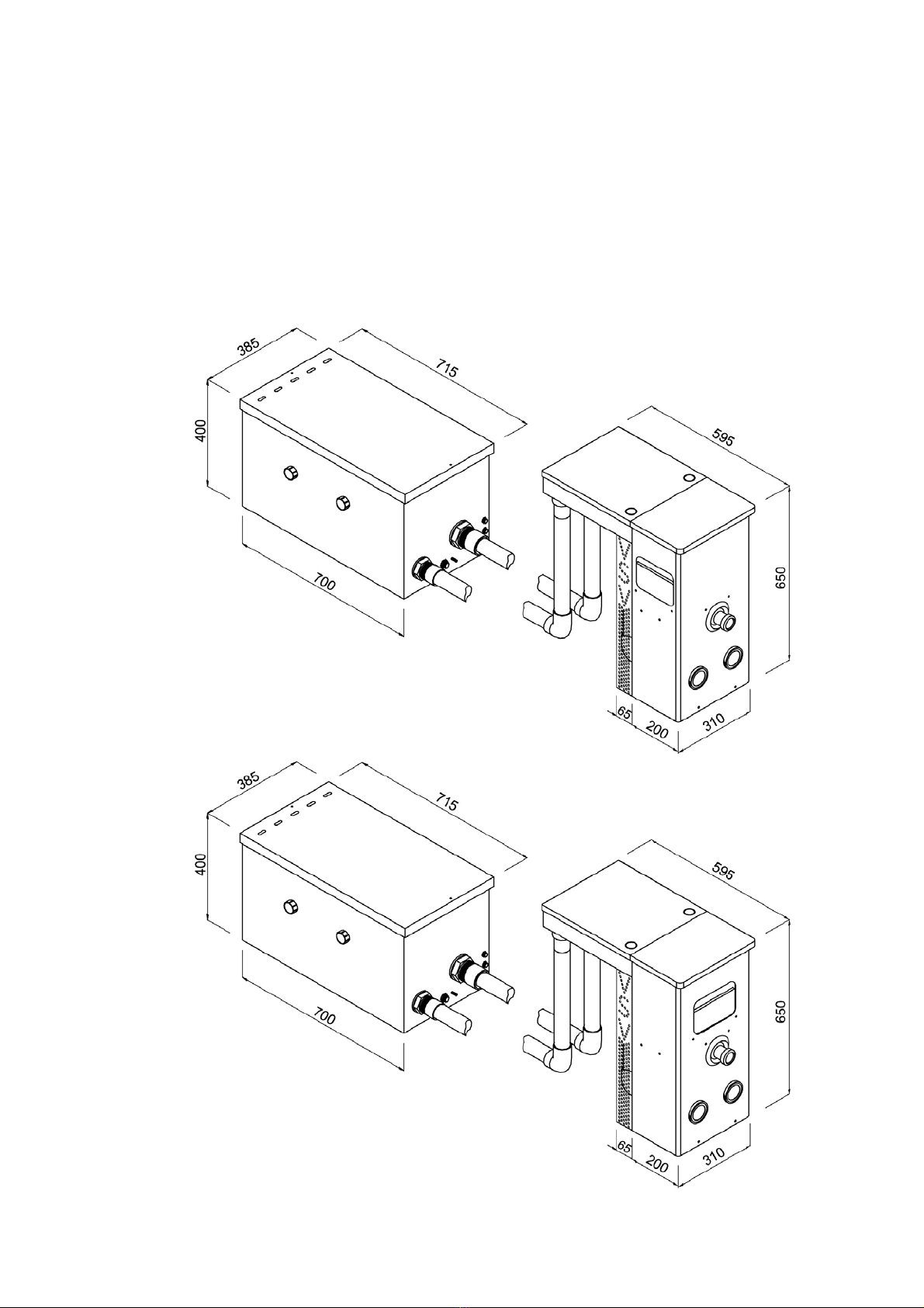
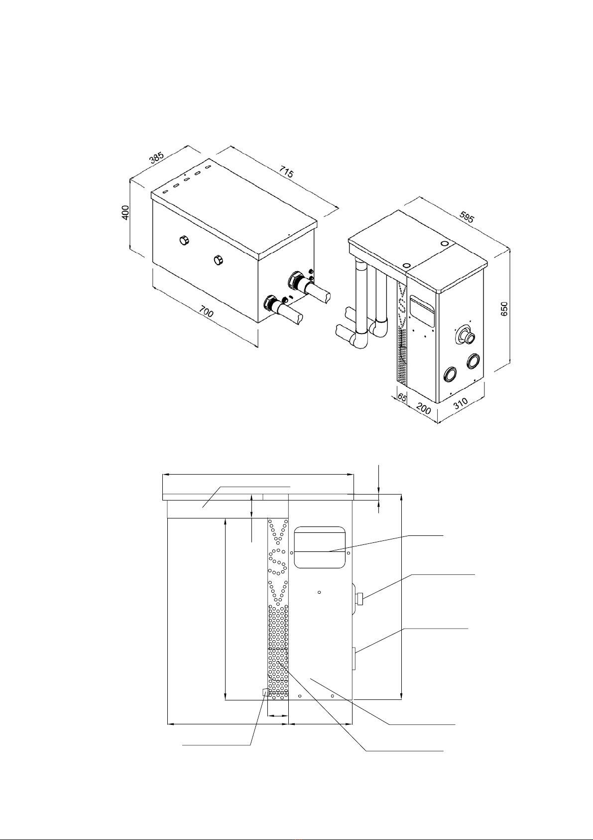
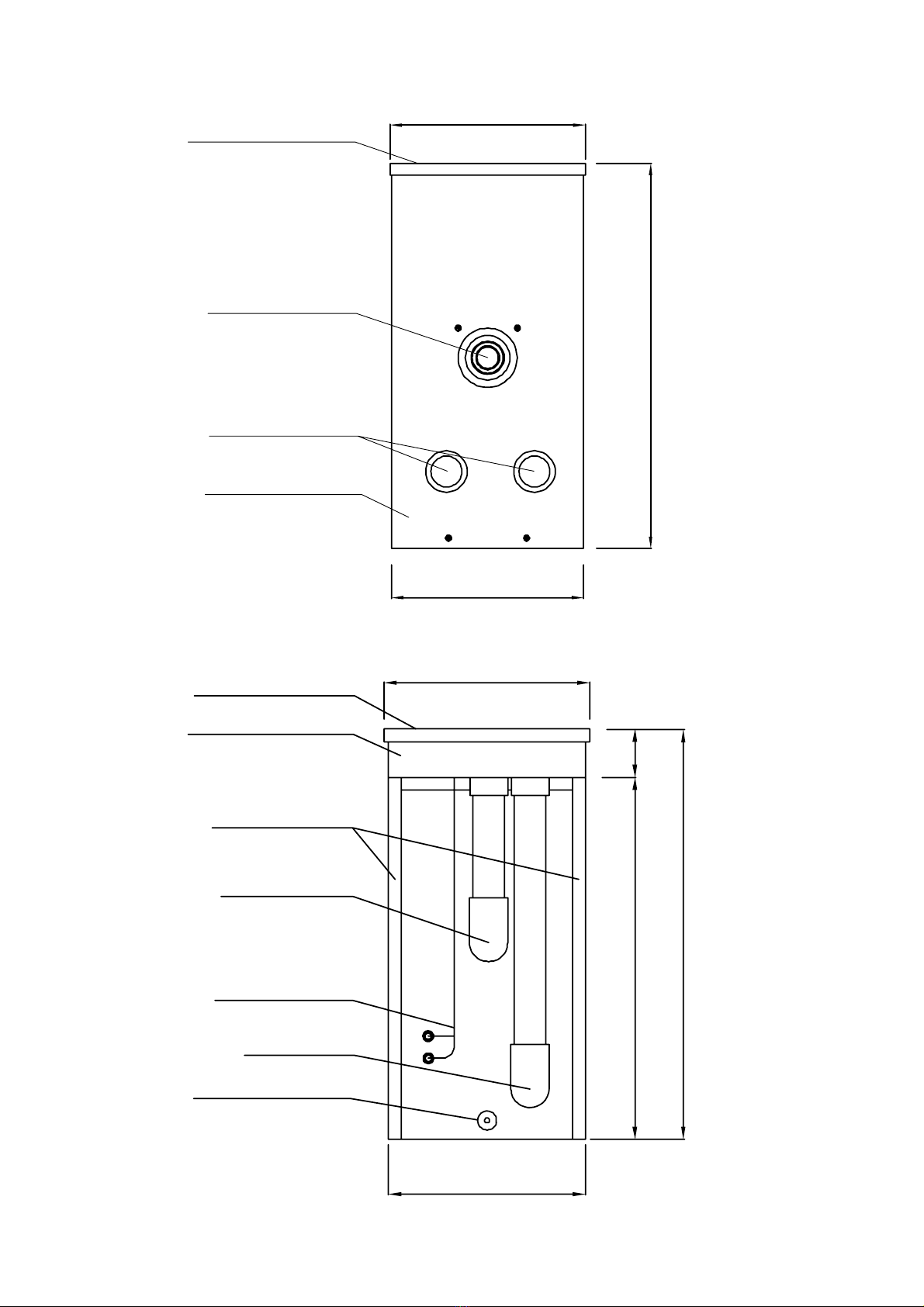
3 - TOTAL VIEW AND DIMENSIONS OF EQUIPMENT ..…………………………………………………… 9-10
3.1 Total view and dimensions of universal blocks …………………......................................... 9
4 - INSTALLATION OF EQUIPMENT …………………………………………………………………………… 11-12
4.1. Installation of universal blocks ………………………………….…………………………………. 11
4.2. Installation of technical compartment of universal blocks ………………………………….. 12
5 - GENERAL SAFETY RULES ……………………………………………………………………………………………………….. 13
Electrical safety…………………………….…………………………………………………………………………………………… 13
Differential switch ………………………………………………………..…………………………………………………………… 13
6 - EQUIPMENT MOUNTING ……………………………………………………………………………………. 14
6.1. Universal blocks mounting …………………………………………………………………………… 14
Automatic water topping-up ……………………………….…………………………………………………………………….. 14
Connection of universal block’s filtration compartment with technical compartment ………………………… 14
a) connection with pump ………………………………………………………………………………..…………………………. 14
b) connection with counter-swimming pneumatic button ………….………………………………………………….. 14
c) laying of spotlight electric cable ……………………………………..………………………………………………………. 14
d) connection with spotlight pneumatic button ……………………………………………………………………………. 14
e) connection of technical compartment with drainage …………………………………………………………………. 14
7 – ELECTRICAL CONNECTIONS ……………………………………………………………………….............. 15-20
Electrical control panel …………………..…………………………………………………………………………………………. 15
Electrical control panel connection scheme ………………………………………………..……………………………….. 16
Multiconductor connection boxes of universal blocks ……………………………………………………………………. 17-18
Heat exchanger electrical connection scheme in the universal blocks ……………….………………………..…. 18
Heat exchanger hydraulic connection scheme in the universal blocks ……………….………………………..…. 19
Electric heater connection scheme in the universal blocks ………………………………………..…………………… 20
8 – GROUND CONNECTION MOUNTING ……………………………………………………………………….. 21
9 – PUTTING INTO OPERATION ………………………………………………………………………………….. 22
9.1. Universal block’s start-up and operation ………………….……………………………………... 22
Initial start-up …………………………..……………………………………………………………………………………………… 22
Timer setting in the electrical control panel …………………………………………………………………………………. 22
Counter-swimming function ……………………………………………..……………………………………………………….. 22
10 – FILTRATION MEMBRANE AND ITS INSTALLATION .………………………………………………….. 23-24
Filtration membrane cleaning and replacement ……………………………………………………………………………. 23
Vacuum-cleaner connection and operation ………………………………………………………………………………….. 24
Big filtration membrane …………………………………………………………………………………………………………….. 24
11 – REPLACEMENT OF SPOTLIGHT BULB …………………………………………………………………….. 25
12 – EQUIPMENT WINTERIZING …………………………………..…………………………………………..... 25

3
13 – SYSTEM DISINFECTION ……………………………………………………………………………………… 26
Ideal chlorine level …………………………………………………………………………………………………………………….. 26
Dosage table ……………………………………………………………………………………………………………………………… 26
14 – PRODUCT MAINTENANCE …………………………………………………………………………………… 27
15 – HOW TO ELIMINATE SMALL MALFUNCTIONS ………………………………………………………….. 27
16 – CENTER OF TECHNICAL SUPPORT …..……………………………………………………………………. 28
CERTIFICATE OF WARRANTY ………………………………………………………………………………. 29
Warranty conditions ………………………………………………………………………………………………………………….. 30

4
1 – GENERAL INFORMATION
Universal filtration blocks VUB series
APPLICATION FIELD
We congratulate You with a purchase of a high-grade product. Universal filtration blocks of VUB series
are intended for operation in all kinds of swimming pools: private, commercial and sport*. Combination
of efficiency and simplified maintenance will bring you total satisfaction.
Please, read attentively present manual for safe connection, effective operation and proper maintenance
of the product. Keep the user guide in the accessible place and appeal to it when needed. The serial
number of the filtration unit is indicated below. In the case of necessity it will help you to obtain more
detailed answers to your questions in the center of technical support.
№
Present user’s guide is intended both for the beginners and for the experienced users and has been
drawn up so that you could carry out step by step necessary works. In the user’s guide are given the
instructions for connection, operation and maintenance of the present product. For easier access to
information User’s Guide has contents. Follow recommendations and instructions of the given user’s
guide and VSV Aqua Group products will enjoy you for a long time.
COPYRIGHTS
Corporation VSV Aqua Group reserves its right to introduce into present guide without any additional
notification the corrections, connected with the improvement of equipment, and also in the case of
inaccuracies and misprints. All such changes will be introduced into the new edition of user’s guide. Visit
regularly our web page in the Internet www.vsv-group.com to obtain the updated information and new
developments.
Corporation VSV Aqua Group possesses full weight of rights on the patents, patent applications, trade
marks, copyrights and other intellectual property, connected with the content of this user’s guide. The
assignment of this user’s guide does not mean the transfer of any licenses or other legal rights for the
use of the abovementioned without official written permission of VSV Aqua Group corporation.
PROTECTION OF ENVIROMENT
PRIORITY TASKS OF OUR COMPANY
Our company constantly develops measures towards economy of the electric power, resources and
decrease of an environmental pollution.
Affecting of new or modified products on an environment is constantly controlled, and new products are
evaluated from the point of view of harmlessness to an environment.
Manufacturer reserves its right of making modifications without additional notification in
construction, design and component parts of product.
* It is forbidden to use filtration systems VUB in the swimming pools with sea water, equipped with
electrolyze or ozone treatment systems. It is forbidden to use filtration systems VSV without grounding.
CE declaration of conformity is issued in compliance with the 89/336/EEC rule of electromagnetic
compatibility and with 73/23/EEC rule of safety requirements for electric equipment.

5
2 – EQUIPMENT DESCRIPTION
STANDARD VERSIONS AND THEIR COMPONENT PARTS
2.1. Principal scheme of universal filtration blocks
VUB15, VUB25 and VUB20/50
grounding bolt
pneumatic switch button
for counter swimming
Technical compartment
pump spotlight transformer
220V/12V/150VA
valve d-63mm
suction pipe
spotlight power
supply cable 2x2,5mm
2
automatic water filling device
spotlight pneumatic switch button
filtration unit cover
skimmer
prefilter
filtration membrane
discharge nozzle
spotlights 2x75W
Filtration compartment
suction nozzle with prefilter
filtration compartment body
discharge
pipe d-50mm
suction pipe d-50mm
drain outlet d-50mm
grounding bolt
valve d-50mm
discharge
pipe d-50mm
technical
compartment body
700x370x400mm
power supply
cable 7x2,5mm
2
multiconductor
connection box
Electrical
control panel
cable 7x2,5mm
2
main power supply
cable 3x2,5mm
2
max.7m
compensators
decorative side plate
console
•Filtration compartment of universal blocks VUB with/without heating includes:
two prefilter baskets + two cups for vacuum cleaner connection, two filtration membranes,
skimmer, water discharge nozzle, two spotlights x 75W, spotlights pneumatic switch button,
counter-swimming pneumatic switch button*, automatic water topping-up device, suction nozzle
with prefilter, regulating support, decorative side plates, grounding bolt;
* VUB15 and VUB25 are supplied with pneumatic button to make possible connection of
counter-swimming function at the replacement of one-speed pump by two-speeds pump;
•Technical compartment of universal blocks VUB can be installed at distance 7 meters
maximum from the pool. Component parts of technical compartment vary depending on model
of the block (see next pages);
•Electric control panel of universal blocks VUB includes: timer, differential switch, protection
fuses of electromotor and spotlight circuits, operational modes switch, spotlight switch;

6
2.1/аBLOCK VUB15
total assigned power 0,85 kW (with spotlights 2x75W):
- one-speed pump 0,7 kW (50 Hz);
- capacity - 15 m3/h;
- total dynamic head H max. 13,5 m;
2.1/b BLOCK VUB25
total assigned power 1,25 kW (with spotlights 2x75W):
- one-speed pump 1,1 kW (50 Hz);
- capacity - 25 m3/h;
- total dynamic head H max. 13 m;
2.1/c BLOCK VUB20/50
total assigned power 1,75 kW (with spotlights 2x75W):
- two-speed pump 0,3/1,6 kW (50 Hz);
- capacity – 20/50 m3/h;
- total dynamic head H max. 19 m;
•Technical compartment includes: one-speed pump 220V (in models VUB15 and VUB25) or
two-speeds pump 220V with control box (in model VUB20/50), spotlights transformer, drain
outlet, multiconductor connection box, connecting pipes with stop valve, grounding bolt.
Technical compartment can be installed at distance 7 meters maximum from the pool.
Technical compartment without electric heater
control box of
2-speed pump
(only for VUB20/50)
main power supply
cable 7x2,5mm
2
multiconductor connection box
pump
spotlight transformer
220V/12V/150VA
drain outlet d-50mm
valve d-63mm
spotlight cable 2x2,5mm
2
suction pipe d-50mm
valve d-50mm
discharge
pipe d-50mm
technical
compartment body
700x370x400mm
grounding bolt

7
2.1/d BLOCK VUB15 + heat exchanger
total assigned power 0,85 kW (with spotlights 2x75W):
- one-speed pump 0,7 kW (50 Hz);
- capacity - 15 m3/h;
- total dynamic head H max. 13,5 m;
2.1/e BLOCK VUB25 + heat exchanger
total assigned power 1,25 kW (with spotlights 2x75W):
- one-speed pump 1,1 kW (50 Hz);
- capacity - 25 m3/h;
- total dynamic head H max. 13 m;
2.1/f BLOCK VUB20/50 + heat exchanger
total assigned power 1,75 kW (with spotlights 2x75W):
- two-speed pump 0,3/1,6 kW (50 Hz);
- capacity – 20/50 m3/h;
- total dynamic head H max. 19 m;
•Technical compartment includes: heat exchanger with electronic thermostat (minimum
heat transfer is 15 kW,maximum -59 kW), one-speed pump 220V (in models VUB15 and VUB25)
or two-speeds pump 220V with control box (in model VUB20/50), spotlights transformer, drain
outlet, multiconductor connection box, connecting pipes with stop valve, grounding bolt.
Technical compartment can be installed at distance 7 meters maximum from the pool.
Technical compartment with heat exchanger
technical
compartment body
700x370x400mm
cable 7x2,5mm
2
multiconductor connection box
pump
spotlight transformer
220V/12V/150VA
suction pipe
drain outlet d-50mm
valve d-63mm
spotlight
power supply 2x2,5mm
2
grounding bolt
discharge
pipe d-50mm
valve d-50mm
heat exchanger
outlet of primary
flow d-26/34
electronic thermostat of
heat exchanger
inlet of primary
flow d-26/34
control box of
2-speed pump
(only for VUB20/50)

8
2.1/g BLOCK VUB15 + electric heater
total assigned power 0,85 kW (with spotlights 2x75W):
12,85 kW (with electric heater 12 kW)
- one-speed pump 0,7 kW (50 Hz);
- capacity - 15 m3/h;
- total dynamic head H max. 13,5 m;
2.1/h BLOCK VUB25 + electric heater
total assigned power 1,25 kW (with spotlights 2x75W):
13,25 kW (with electric heater 12 kW)
- one-speed pump 1,1 kW (50 Hz);
- capacity - 25 m3/h;
- total dynamic head H max. 13 m;
2.1/i BLOCK VUB20/50 + electric heater
total assigned power 1,75 kW (with spotlights 2x75W):
13,75 kW (with electric heater 12 kW)
- two-speed pump 0,3/1,6 kW (50 Hz);
- capacity – 20/50 m3/h;
- total dynamic head H max. 19 m;
•Technical compartment includes: electric heater of laser type with control box, one-
speed pump 220V (in models VUB15 and VUB25) or two-speeds pump 220V with control box (in
model VUB20/50), spotlights transformer, drain outlet, multiconductor connection box,
connecting pipes with stop valve, grounding bolt. Technical compartment can be installed at
distance 7 meters maximum from the pool.
Technical compartment with electric heater
electric heater
control box
multiconductor connection box
pump
spotlight transformer
220V/12V/150VA
suction pipe
drain outlet d-50mm
valve d-63mm
spotlight
power supply 2x2,5mm
2
grounding bolt
discharge
pipe d-50mm
valve d-50mm
electrical heater
technical
compartment body
700x370x400mm
control box of
2-speed pump
(only for VUB20/50)
cable 7x2,5mm
2

9
3 –TOTAL VIEW AND DIMENSIONS OF EQUIPMENT
3.1. Total view and dimensions of universal blocks
VU15, VUB25 and VUB20/50
20
650
75
575
595
380 200
65
filtration unit holder
skimmer
discharge nozzle
spotlights 2x75W
filtration unit body
decorative side plate
adjustable support

10
324
310
650
Filtration unit cover
spotlights 2x75W
discharge nozzle
filtration unit body
310
324
76
650
575
filtration unit cover
discharge pipe
suction pipe
spotlight power
supply cable
filtration unit holder
decorative grate
adjustable support

11
4 – INSTALLATION OF EQUIPMENT
4.1. Installation of universal filtration blocks VUВ15, VUВ25 and VUB20/50
Install filtration block carefully not to damage a waterproofing covering (liner). Submerge the block into
water, regulate adjustable support, after that fix it with fixing bolts on pool’s wall in the specially foreseen
for that places (see the drawing “ Top view”).
100
70
200
filtration unit fixing bolts
upper reinforcement technical compartment
suction pipe d-50mm
back filling
drain outlet
reinforcing mesh
down reinforcement
reinforcing mesh
swimming pool concrete shell
spotlight
discharge nozzle
skimmer
water level in swimming pool
filtration block
adjustable support
TOP VIEW
310
20
580 200180
200 100 110
grounding bolt
discharge pipe
prefilters
skimmer
discharge nozzle
spotlight 75W
spotlight 75W
automatic
water-filling
spotlight power
supply cable
suction pipe
fixing bolt M10x120
flexible pipe connector
filtration unit body

12
filtration unit
technical compartment
filtration unit
level of playground
around swimming pool
swimming
pool
NO
level of playground
around swimming pool
swimming
pool
YES
technical
compartment
above
swimming pool
playground level
technical compartment
playground stone
coping stone
filtration block
swimming pool concrete shell
down reinforcement
swimming pool wall
liner lock mount profile
back filling
waterlevel
inswimming
pool
max.7m.
4.2. Installation of universal blocks’ technical compartment
Preparation of the base for technical compartment
Technical compartment should be installed in the location zone 2 (VDE 0100-702)
For installation of the technical compartment create a basis from sand and rubble. Thickness of a basis should
provide the satisfactory base. Sizes of the pit should not restrict your access for installation of the pipeline and
electric cables. The overhead part of the technical compartment without cover should be the same level as platform
around swimming pool. Carry out levelling of technical compartment with the help of a level meter, make sand
backfilling and fix it.

13
5 - GENERAL SAFETY RULES
The filtration unit can be heated up under exposure of direct sunbeams. Don’t touch the heated parts of
filtration unit during the time of usage.
Do not allow the usage of filtration equipment by people (including children) with depressed
psychophysical capabilities or with insufficient experience and knowledge, with exception of cases, when
they are watched closely, or they were instructed by responsible for their safety person. Look after the
children , make sure, that they are not playing with equipment.
The packaging elements of filtration equipment should not be left in the places easy of children’s access,
because they are the potential sources of danger.
ELECTRIC SAFETY
To avoid the danger of injuries or electric shock during connection and operation of equipment always
follow the safety regulations currently in force in your country.
Please, read attentively this user’s guide and make sure that the instructions given in it are clear for you.
You must know about the consequences, which can be caused by the actions undertaken by you. Don’t
undertake any actions, which are not described in this guide, since they can lead to the appearance of
the situation presenting danger to the people and/or equipment.
Keep this guide in good conditions and if necessary transfer to next owner.
All electric connections should be carried out by the qualified specialist electrician with observance of
enclosed instructions and connection schemes. The connections should comply with electrical norms of
your country. The electrical control panel should be installed beyond distance 3.5 meters from swimming
pool. All connections in the electrical control panel should be well tightened.
Power supply line should be connected so, that fuse 16A will be placed at the beginning of panel’s power
supply circuit (before differential protection).
An all pole disconnection should be provided in the fixed wiring
Connection to the electrical network is carried out by connecting the copper cable 3x2.5mm2(for cable
with length up to 20m) to the top terminals of the differential switch in the electrical control panels of
filtration equipment and heater, observing polarity.
Bury the cables in protective pipe. If cables are not protected, it is obligatory to cover a top of a cable
with warning band. Under a road or path the cables should be buried at depth not less than one meter.
In all other cases depth of the cable - 0.6 m.
CAUTION!The cover of a technical compartment in which there is electric equipment, should be safely
locked and fixed with screws. Disconnect power supplies before any works inside technical compartment
of the filtration equipment. The filtration unit must be without fail grounded! Please, check up norms of
your country.
DIFFERENTIAL SWITCH (GROUND FAULT CIRCUIT INTERRUPTOR)
CAUTION! Filtration unit is connected with electrical power supply only through 30mA differential switch
(GFCI). Your electrical control panel of filtration equipment is equipped with differential switch, which
ensures essential protection against electrical shocks and disconnects filtration unit in the case of
accident.
IMPORTANT NOTE! You must test differential switch at least once a month. To do the test, it is
necessary to press test button on the differential switch. At the moment when the safety mechanism is
tripped you should hear a click of switching-off. Then, switch the differential switch back on.
The test should be carried out when the differential switch is under voltage. If, while pressing the test
button, the differential switch is not switching-off, it is necessary to turn off the electricity and to call out
the qualified electrician or your regional agent for elimination of malfunction.

14
6 – EQUIPMENT MOUNTING
6.1. Universal blocks mounting
WATER TOPPING-UP
Lead a pipe of the water pipeline to filtration block and connect it to the ingoing
bushing (a thread of 3/8”). Ensure leak resistance of the joint.
ATTENTION! The system of automatic water filling is designed for water pressure
of 4.5 Bars maximum.
ATTENTION! After the swimming pool is full with water, adjust the regulating screw of the automatic
water toppin-up device so, that water level will not be lower the upper edge of the skimmer shutter.
CONNECTION OF BLOCK’S FILTRATION COMPARTMENT AND TECHNICAL COMPARTMENT
а) connection with pump
With the help of pipes d-50mm connect between themselves suction and discharge
openings as it is specified in the “Universal filtration blocks installation scheme”.
Pipes are necessary to lay down so that they will form compensators in order to
prevent pipes damage from temperature expansion. It is necessary to lay down
pipelines in a depth corresponding to a climatic zone of your region.
b)connection with pneumatic button of counter-swimming
(for model VUB20/50)
To avoid damage of pneumatic hose during soil back filling, it is necessary to lead it
in protective pipe of suitable diameter. Lead a pneumatic hose through tightening
gland in the case of block’s technical compartment. Connect pneumatic hose with pneumatic button in
the console of the filtration compartment and pneumatic switch in the control box of the pump in the
technical compartment.
CAUTION! It is necessary to lay the pneumatic hose smoothly, not bending it!
c) laying of spotlight electric cable
(follow instructions from chapter “General safety rules”)
Lay a protective pipe of suitable diameter between block’s filtration compartment
and technical compartment. Lead in it a copper cable 2х2,5mm2. One end of a cable
should be in a technical compartment near the spotlight transformer, and the second end near terminals
in filtration compartment. With the help of terminals connect cable wires in the filtration compartment.
Connect terminals between themselves. Push the tube on the connected terminals. Heat the tube by air-
heater (blow-drier) so, that it will crimp tightly the terminals. Connect the second end of cable to
transformer. Tighten cable gland in the technical compartment of filtration block.
d) connection with spotlight pneumatic button
To avoid damage of pneumatic hose during soil back filling, it is necessary to lead it
in protective pipe cover of suitable diameter. Lead a pneumatic hose through
tightening gland in the case of block’s technical compartments. Connect pneumatic
hose with pneumatic button in the console of the filtration compartment and pneumatic switch in the
spotlight transformer.
CAUTION! It is necessary to lay the pneumatic hose smoothly, not bending it!
e) connection of technical compartment with drainage
With the help of pipes 50mm connect drain outlet of technical compartment with drainage.
Create a slope for pipelines to avoid water level rising inside a technical compartment.
ATTENTION! If you connect the drainage pipeline to other drainage systems, carry out the
joint so that water from other drainage systems will not get into drainage of the technical
compartment.

15
differencial switch fuse 16A
(pump's second speed) fuse 6A
(spotlight and pump)
programmable timer
spotlight switch
Electrical control
panel case
240x190x98mm
main power supply cable
7x2,5mm
2
to pump and
spotlight transformer
main power supply
cable 3x2,5mm
2
filtration unit
operational mode
switch 3 positions
Manual
0
Auto
16A 6A On
Off
7 – ELECTRICAL CONNECTIONS
ELECTRIC CONTROL PANEL
differencial switch fuse 16A
(pump's second speed) fuse 6A
(spotlight and pump)
programmable timer
ground terminal
strip
outgoing terminal
strip to spotlight
transformer
yellow-green
ground wire 2,5mm
2
electrical control panel
case 240x190x98mm
main power supply cable
7x2,5mm2 to pump and
spotlight transformer
main power supply
cable 3x2,5mm
2
outgoing strip
terminal to pump 1,2,3
yellow-green
ground wire 2,5mm
2
12 56
56
3
123
16A 6A

16
CONNECTION SCHEME OF ELECTRICAL CONTROL PANEL
in universal blocks
Connection of power supplies is made to the top terminals of the differential switch, observing polarity. Main power
supply cable of pump and spotlight transformer is connected to terminals according marking on the cable wires and
enclosed scheme.

17
MULTICONDUCTOR CONNECTION BOXES
of universal blocks
Lead pump and transformer main power supply cable into technical compartment through intended for it tightening
gland. Tighten a nut of a gland to avoid water leakage into technical compartment. Lead a cable into connecting box
and connect wires according enclosed diagram.
MULTICONDUCTOR CONNECTION OF FILTRATION UNITS (without water heating)
5
6
2
3
blue
yellow-green
yellow-
green
grounding
wire 2,5mm
2
cable 7x2,5mm
2
to electric control panel
brown
cable 2x1,0mm
2
to spotlight
transformer
black (only for VUB20/50)
spotlight pneumatic
switch
1
cable 4x2,5mm
2
to pump 20/50m
3
(cable 3x1,5mm
2
to pump 15, 25m
3
)
MULTICONDUCTOR CONNECTION BOX OF FILTRATION UINITS (with heat exchanger)
cable 2x1,0mm2
to spotlight
transformer
brown
cable 7x2,5mm2
to electric control panel
cable 3x1,0mm2
to thermostat
blue
brown
yellow-green
grounding wire
2,5mm25
6
2
1
3
4
grey
blue
yellow-green
spotlight pneumatic
switch
black (only for VUB20/50)
cable 4x2,5mm2to pump 20/50m3
(cable 3x1,5mm2to pump 15, 25m3)

18
MULTICONDUCTOR CONNECTION BOX OF FILTRATION UNITS (with electric heater)
cable 2x1,0mm
2
to spotlight
transformer
spotlight pneumatic
switch
brown
cable 7x2,5mm
2
to electric control panel
cable 2x1,0mm
2
to electric heater
blue
brown
yellow-green
wire 2,5mm
2
to ground
yellow-green
blue
5
6
2
11
3
cable 4x2,5mm
2
to pump 20/50m
3
(cable 3x1,5mm
2
to pump 15, 25m
3
)
black (only for VUB20/50)
ELECTRICAL CONNECTION SCHEME OF HEAT EXCHANGER
in universal blocks VUВ15, VUВ25 and VUB20/50
Make connection of mounted equipment and connect with electrical control panel of filtration unit according
enclosed diagram.
electric control panel
of filtration unit thermal protection
switch
switch
heat exchanger
circulation pump
electromagnetic
valve
phase
(from electronic
thermostat)
N

19
HYDRAULIC CONNECTION SCHEME OF HEAT EXCHANGER
in universal blocks VUВ15, VUВ25 and VUB20/50
Connect heat exchanger with gas boiler according enclosed scheme.
Choose the circulation pump of necessary capacity according enclosed table.
Table of circulation pumps for heat exchanger
Capacity of the circulating
pump Power of the circulating
pump
0,72 m3/h 15 kW
1,44 m3/h 29 kW
2,16 m3/h 44 kW
2,88 m3/h 59 kW
circulation pump
of heating
valves
circulation pump
of heat exchanger
thermal protection switch
pipe 26/34
technical compartment
of filtration unit
heat exchanger
pump
electronic
thermostat
suction pipe
discharge pipe
expansion
tank
filtration unit
electrical
control panel
electromagnetic
valve
non-return valve
boiler
3-position valve

20
CONNECTION SCHEME OF ELECTRIC HEATER
in universal blocks VUВ15, VUВ25 and VUB20/50
Power supply connection is made on the top terminals of the differential switch, observing
alternation of phases. Pay attention that the cross-section and quantity of cable wires should
correspond to your electric heater model
Power supply
single-phase
heater
Power supply
three-phase
heater
- neutral;
- phase;
- ground;
- neutral;
- phase;
- ground;
Electrical
control panel
- neutral;
- 3-phase;
- ground;
- neutral;
- 3-phase;
- ground;
main
power supply main
power supply to electric heater
control box
cable 2x1,0mm2
to connection box
electric heater
control box
cable 2x1,0mm2
to heater
cable 4x2,5mm2to heater
cable 4x6mm2to electric heater
electrical control panel
3 phase
6 kW
9 kW
12 kW
fuse
10A
16A
20A
cable
4x2,5mm
2
4x4mm
2
4x6mm
2
1 phase
6 kW
fuse
32A
cable
3x6mm
2
Yellow-green
Brown
Blue
Brown
Blue
Yellow-green
This manual suits for next models
2
Table of contents