Initial Setup
IPanel 3700/4200
Please verify the following items are included with your shipment; camera with
mounting bracket, camera power supply, wireless keyboard, PC power supply,
DVD player power supply, panel IR remote, and software (including Windows XP
Pro).
A. Remove camera and
camera mounting plate from the
camera box (located in the
accessories box).
C. Use two screws to mount camera
bracket and camera to the mounting plate
holding the PC. Be careful not to over
tighten the screws.
Align the camera bracket with the front
of the monitor and stick it down with the
double sided tape.
B. Using a Philips screwdriver remove
the large silver screw from the bottom of
the camera and use it to mount the
camera mounting plate to the camera. Be
careful not to over tighten the screw.
Note: The L-shaped part of the mounting
plate (containing two small holes) should
face toward the back of the camera.
A. Connect the power supply
adapter-- a transformer (“brick”)
with a large 4-prong plug on one
end to the computer’s power
receptacle located on the bottom
left side of the computer. The
power supply adapter is found in
the accessory box.
B. Connect an RJ45 cable from your Internet or
LAN (local area network) connection to the
bottom of the computer in either RJ45 port.
1. Camera mounting
2. Power and network
C. Check all cable to ensure none came loose
during shipping.
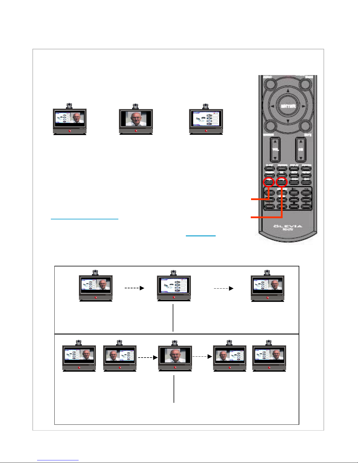
IPanel Systems
“Easyto Drive”
Oneclick operation
AC
Optional
Cable
Internet/LAN
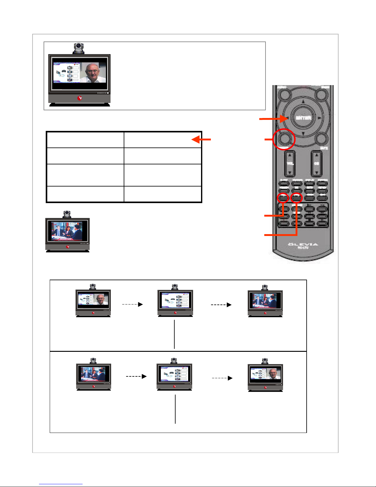
All-In-OneProfessional Solution
VTELIPanel 3200/4200
26/32”
Multimedia
Presentations
Internet
&
PC Applications
Videoconferencing
with
DataSharing
HDTV
+ +
D. Connect the two cables (top of the LCD monitor) to
the camera --Yellow to composite, black to RS-232.
Make sure the camera power supply is connected to
camera and AC outlet.
All camera cables must be connected before
powering on the computer.