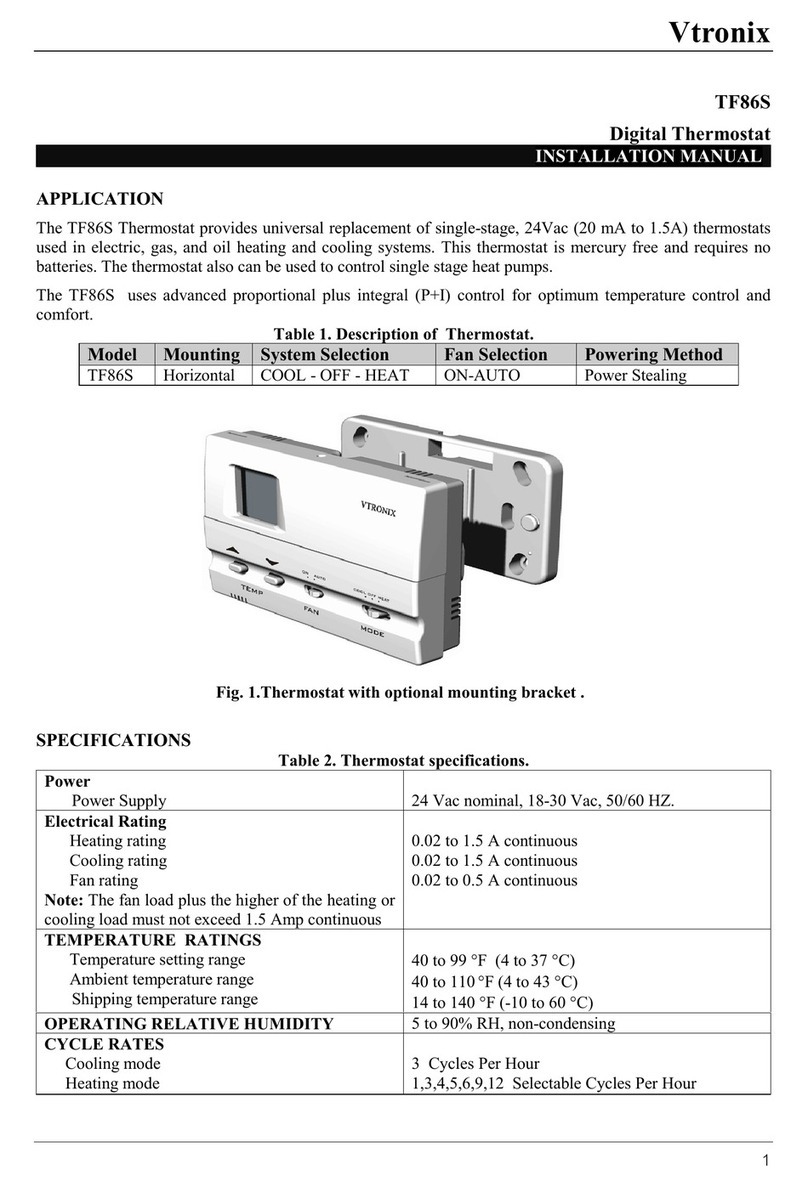
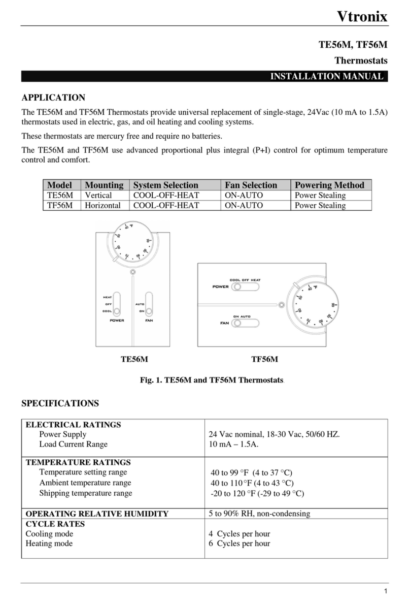
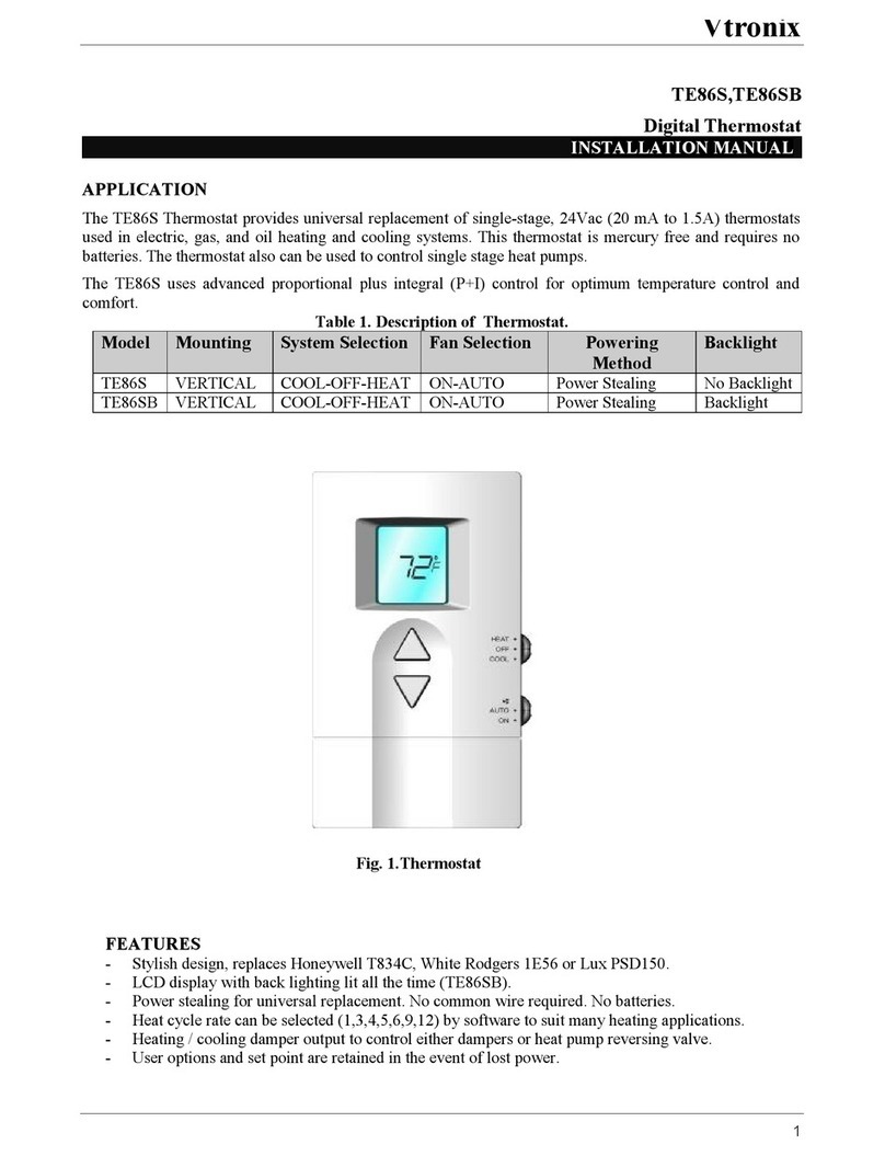
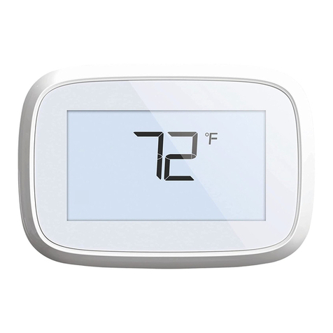
Vtronix TE80SB User manual

Vtronix
1
TE80SB
Programmable Digital Thermostat
INSTALLATIONMANUAL
APPLICATION
TheTE80SBThermostatprovidesuniversalreplacementofsingle-stage, 24Vac(20 mAto1.5A)thermostats
usedinelectric,gas,and oil heatingand coolingsystems.Thisthermostatismercuryfreeand requiresno
batteries. Thethermostatalsocanbeusedtocontrolsinglestageheatpumps.
TheTE80SBusesadvancedproportionalplusintegral(P+I) controlforoptimumtemperaturecontroland
comfort. Table1. DescriptionofThermostat.
Model Mounting SystemSelection FanSelection Powering
Method Backlight
TE80SB VERTICAL COOL-OFF-HEAT ON-AUTO PowerStealing Backlight
Fig. 1.Thermostat
FEATURES
-7-Dayprogrammablewith4programs/day.
-Stylishdesign, replacesHoneywellT834C, WhiteRodgers1E56 orLux PSD150.
-LCDdisplaywithbacklightinglitall thetime.
-Powerstealingforuniversalreplacement. Nocommonwirerequired. Nobatteries.
-Heatcycleratecanbeselected(1,3,4,5,6,9,12)bysoftwaretosuitmanyheating applications.
-Heating/coolingdamperoutputtocontroleitherdampersorheatpumpreversingvalve.
-Useroptionsandsetpointareretainedintheeventoflostpower.

Vtronix
2
SPECIFICATIONS Table2. Thermostatspecifications.
Power
PowerSupply 24 Vacnominal, 18-30 Vac, 50/60 HZ.
ElectricalRating
Heatingrating
Cooling rating
Fanrating
Note: Thefanloadplusthehigheroftheheatingor
cooling loadmustnotexceed1.5Ampcontinuous
0.02 to1.5Acontinuous
0.02 to0.5Acontinuous
TEMPERATURERATINGS
Temperaturesetting range
Ambienttemperaturerange
Shippingtemperaturerange
40 to99 °F(4to37 °C)
40 to110°F (4to43 °C)
14 to140 °F (-10 to60 °C)
OPERATINGRELATIVEHUMIDITY 5to90%RH, non-condensing
CYCLE RATES
Coolingmode
Heatingmode 4CyclesPerHour
1,3,4,5,6,9,12 SelectableCyclesPerHour
DIMENSION
Fig. 2.Thermostatdimension

Vtronix
3
INSTALLATION
Readtheseinstructionsthoroughlybeforeinstalling
product. Failuretofollowtheseinstructionscould
damagetheproductorcauseahazardouscondition.
Checkthevoltageand currentratingsontheproduct
toensurethatitissuitableforyourapplication.
Installermustbea trained, experiencedservice
technician. Checkproductforproperoperationafter
installation.
CAUTION
Damagetoheatingandcoolingsystemmayoccur.
Disconnectpowerfromtheequipmentat themain
breaker/fuseblockwhileinstallingthethermostat.
MountingLocation.
Mountthethermostatapproximately5ft.(1.5m)
abovethefloorina locationthatisfreefromdirect
sunlight, heatfromappliances, hotorcoldairfrom
ducts, concealedpipesandchimneys, and draftsor
deadspotsbehinddoorsorincorners. Donotmount
onexteriorwall, ifpossible. Failuretolocate
thermostatmountingasindicatedwill resultinpoor
temperaturecontrol.
NOTE: Levelthermostatmountingisforappearance
onlyandisnotrequiredforproperthermostat
operation.
MountingThermostat
Takeoutthebackplatebyremovingthelocking
screw(ifany)atthebottomofthethermostat. Use
flatheadscrewdrivertounlockthesnaps. Liftand
pull itup toremovebackplate.
Using backplateasa guide,marktwomounting
holesonthewall. Drill twomountingholes. Place
anchors(provided)intotheholesuntil flushwith
thehole. Positionbackplateonthewalland
threadthewiresfromtheheatingandcooling
equipmentthrough thewiringhole. Holding the
backplateinplaceonthewall, secureittothe
wallusingmountingscrews(provided).
Wiring
Pull theconnectorfromthebackofthermostatby
insertingscrewdriveratthebaseofconnectorand
gentlyliftup.
Fig. 6a.Wiringdiagram.
Color-coded18-22 gaugewireisrecommended
forwiring. Allwiringmustfollowlocal
electricalcodelocatedneareachterminal.
Fig. 4.Installing
backplate
Fig. 3.Takingout
backplate
Fig. 5Liftingtheconnector

Vtronix
4
Placetheterminalbacktothethermostat, make
sureithasthesameorientationlikeinthepicture
describedattheback. Snapthethermostattoits
backplate.
Fig. 7.Connectingwire.
Loosentheterminalscrew, stripthewireand
connectthewireasshowninfig7. Firmlytighten
terminalscrew
whenfinished.
Set-upswitch(E/F)
WARNING
Fire Hazard.
Failuretosettheset-up switchtotheEposition
whenelectricresistanceheatisusedmayresult
intheoverheatingoftheelectricheaterelements
duetoimproperfanoperation.
Theset-up switchisaninternalswitch(E,F)
locatednearthewiringterminals. Itisusedto
selectproperfanoperationfortheheating
systembeingused.
qTheEpositionisforelectricheatand single
stageheatpumpapplications.
qTheF positionisforfuelapplications.
Fig. 8.Setupswitch.
Fig. 6b. WiringDiagramfor
singlestageheatpump.
HEATPUMPWITH
HEATACTIVE
REVERSINGVALVE
HEATPUMPWITH
COOLACTIVE
REVERSINGVALVE
*Note:Set-up
switchmustbe
inEposition.
*Note:Set-up
switchmustbe
inEposition.
Fig. 9.Installingthermostat.

Vtronix
5
TestingHeating/CoolingEquipment. (OP:01)
Whileintheinstallersetup, slidethemodeswitchto
heattooperatetheheatingequipmentorcoolto
operatethecoolingequipment. Thedisplaywillshow
either00 or01on thelowerrightarea and eitherheat
orcoolasselectedbythemodeswitch.
a.If theequipmentisoff, press ∇ keytoturniton
(ifnot, checkthewiringortheequipment).
b.Press
∇
keyagaintoturnoff.
Exampledisplayshowing
Heatequipmentisoff.
Exampledisplayshowing
Heatequipmentison.
Exampledisplayshowing
Heatequipmentisoff.
Exampledisplayshowing
Heatequipmentison.
Nowfollowthefollowingstepstochangeeachofthe
settings. Eachtimeyoupress ∆ key, youwilladvance
tothenextoperatingparameter.To
gobackyoumust
re-entertheinstallersetup asdescribedabove.
INSTALLERSETUP
Thefollowinginstructionsprovideinformation to
testtheheating /coolingequipmentandtochange
operatingparametersfromthefactorysettings.
EnterInstallerSetup
a.Use ∆ or ∇ keytosetthetemperaturesetpoint
to52
°F (or11 °C).
Fig. 10.Securethefrontcover.
Securethethermostatbytighteningthescrew
providedtoprotectthethermostatfromunwanted
access.
OR
b.Press ∆ and∇ key
simultaneouslytoenterinstaller
setup.
Setting
°
C/
°
FIndication. (OP:02)
Whileintheinstallersetup,
a. Press ∆ key, thedisplaywill
show °F/°Cindication.
b. Press ∇ keytochange °F or °C
indication.
NOTE:Factorysetting
is°Findication.

Vtronix
6
Table4. Recommendedcyclerate(CPH).
SYSTEM CPHSETTING
SteamGravity 1
Hydronicheat 3
GasorOil forcedair 6
Electricheat 9
Note:Iftheequipmentmanufacturerecommends
adifferentrateusetheratespecifiedbythe
equipmentmanufacture.
SettingHeatingCycleRate. (OP:03)
Incooling, thecyclerateisfixedat4Cyclesper
hour.Tosetthecyclerateinheating;whilein
installersetup,
a. Press ∆ key, thedisplaywill
showtheheatcyclerate.
b.Press ∇ keytochangetheheat
cyclerateto1,3,4,5,6,9or12
cyclesperhour.
Note:Thedefaultissetat6cycleper hour.
Table4istherecommendedcyclerate. The
installer shouldconsultwiththeheating
equipmentmanufacturerforproper use.
Settingcoolingalgorithm. (OP:04)
Thecoolingalgorithmcanbeselectedasnormalor
aggressive. Foraggressive, thesystemwill cooldown
theroomtosettingpointfasterthannormalalgorithm.
However, anovershootmightbeoccurredinsome
situations.
a.Press ∆ keytoshowthecooling
algorithm.
b.Press ∇ keytochangealgorithm.
0=Normalalgorithm(default).
1=Aggressivealgorithm.
SettingCoolingDelayTime. (OP:05)
Insomeapplications, thereisa necessitytodelaythe
operationofthecoolingequipmentforprotection
purposes. Whileintheinstallersetup,
a. Press ∆ key. Thedisplaywill
showcoolingdelaytime.
b. Press ∇ keytoselectthecooling
delaytime(0,3,5minutes).
NOTE:Thedefaultsettingis3
minutes.
Temperatureoffset. (OP:06)
Thetemperaturecanbeoffsetfrom+3 to-4 °F to
eliminatetheeffectofinstallinglocation(e.g. direct
sunlight). Thethermostatwillindicateroom
temperaturebyusingactualreadingplus(or
minus)
theoffsetvalue.
a.Press
∆
keytoshowtemperature
offset.
b.Press ∇ keytoselectoffset
value(default=-1 °F).
NOTE:Thedefaultsettingis-1 °F.

Vtronix
7
OPERATION
SystemSetting
Usemodeswitchforselectingsystemoperation.
qCool:Thethermostatcontrolsthecooling
system.
qHeat:Thethermostatcontrolstheheating
system.
qOff :Bothheatingand coolingareoff.
FanSetting
Fanswitchsettingsare
On:Fansymbolisindicatedon
thedisplay. Thefanruns
continuously. Usedtoimproveair
circulationandairquality.
Auto:Fanand Autosymbolsare
indicatedonthedisplay.
Forcoolingmode:
Thefanstartsand stopswith
cooling equipment.
Forheatingmode:
qIf setup switchisat‘F’position, thefanis
controlleddirectlybytheheatingequipment.
qIf setup switchisat‘E’position, thefanstarts
and stopwithheatingequipment.
MinimumOffTimer
Forcooling, whenthethermostat
callsforoperationwhilethe
minimumoff timerisnotexpired,
the
starsymbolkeepsflashing.
BackLighting
Thethermostatfeatures
a backlightthatwill
illuminateall thetime.
Theusercaneasilysee
theLCDscreenunder
dimlightsituation.
ExitInstaller Setup.
Press ∆ keyagaintosaveall
settingsandexittothenormal
operatingmode.
Timeformat. (OP:07)
Theclockonthedisplaycanbeselectedtoshow
either24-hourorAM/PMformat. Whileinthe
installersetup,
a.Press
∆
keytoshowtimesetting.
b.Press ∇ keytoselecttime
settingasfollow.
0:24-hourformat.
1:AM/PMformat.
NOTE:After returntonormaloperation, change
thesetpointtothedesiredroomtemperature,
otherwisetheprogrammedsetpointwill beused.
NOTE:Thedefaultsettingis1:AM/PMformat.

Vtronix
8
PROGRAMMINGSCHEDULE
Selectsystemswitchinheatorcoolmode.
Press “PROG” toenterprogrammode. Display
will prompttoselectday.
Press ‘PROG’and selectsetpoint
bypressing ∆ or ∇ key.
HeatorCooldependsonsystem
switchselection. If systemswitch
isinoffposition, useCOOLmode
asdefault.
Press ‘PROG’toconfirmthesetting.
Press ‘PROG’againtoproceedto
nextprogram.
AfterP4isprogrammed, press ‘PROG’once
moretoexit. Press the‘RUN’button atany
timetoexitprogrammode.
Note:Defaultsettingcanberestoredto
memorybypressingHOLDand RUN buttons
atthesametimefor3seconds.
Press ∆ or ∇ keytoselectdesiredprogrammingperiod
asbelow.
Press ‘PROG’toproceed.
Thethermostatwilldisplay
program‘P1’and promptto
adjusttime.
Press ∆ or ∇ keytoselecthour
then
press ‘PROG’toproceed.
Press ∆ or ∇ keytoselect
minutethenpress ‘PROG’
toproceed.
Weekday
Weekend
7-Day >Weekday>Weekend>Monday>Tuesday
Sunday<Saturday<Friday<Thursday<Wednesday
V
Tableofprogrammingperiod.
Defaultsetting:
WeekDay WeekEnd
Time Heat Cool Heat Cool
P1 6:00 AM70°F 74°F70°F74°F
P2 8:00 AM 65°F 78°F70°F74°F
P3 5:00 PM 70°F 74°F70°F74°F
P4 10:00 PM 65°F 78°F65°F78°F

Vtronix
9
ADJUSTINGTEMPERATURE
Adjustingthetemperatureduringany programwill
makethethermostattotemporarilyusethisset
pointuntilthenextprogram.
Duringany program, press ∆ or ∇
keystochangesetpoint. Flashing
‘KEY’iconindicatestemporary
mode.
Thenextprogramtimerwillautomaticallycancel
temporarymode. ‘KEY’iconwill disappearedand
setpointwill beupdatedtotheprogrammeddata.
HOLDTEMPERATURE
Press the‘HOLD’buttontomaintaina setpoint
foranextendedperiodoftime, forexample,
whengoingonvacation.
Pressing∆ or ∇ keyswillchange
theholdtemperature. ‘KEY’icon
indicatesholdmode.
Tocancel, press ‘HOLD’button
againuntilthekeyiconhas
disappeared. Setpointwillbe
updatedtotheprogrammeddata.
NotethatonlytheHOLDbutton
canbeusedtoexittheHOLDtemperature.
CLOCKADJUSTMENT
Theclockneedstobeadjustedwheninstalled. The
clockwillberetainedfora fewhoursincaseof
powerinterruption.
Press ‘CLOCK’innormalmodetoadjusttheclock.
Note:Press HOLDand CLOCKbuttonsat
thesametimetotogglebetween°C/ °F.
Note:Press CLOCKandRUN buttonsat
thesametimetotogglebetweenAM/PMand
24Hformat.
Press
∆
or
∇
keystosethour.
Press ‘CLOCK’toconfirm
and proceed.
Press
∆
or
∇
keystoset
minute. Press ‘CLOCK’to
confirmandproceed.
Press
∆
or
∇
keystosetDay.
Press ‘CLOCK’toconfirm
and exit.
Thenextprogramtimerwill
canceltemporarymode. ‘KEY’
iconwillstopflashingand setpoint
will beupdatedtoprogrammeddata.
Press the‘RUN’button tocanceltemporary
modeand followtheprogramschedule.

Vtronix
10
SYSTEMCHECKOUT
CoolingCheckout
WARNING!Donotoperateincoolingmodewhentheoutdoortemperature isbelow50 °F(10 °C)
otherwisethecompressormightbedamaged.
1. SlidemodeswitchtoCOOL, Oterminalwillgetenergized.
2. Pressing ∇key tolowerthesetpointbelowroomtemperature.Thestarsymbolisshownonthedisplay.
If flashing, thecompressordelaytimeisnotyetexpired. If litsteady, thecompressorisonand terminal
Yisenergized.
3. Press ∆ keyuntilsetpointishigherthanroomtemperature.Thestarsymbolisremoved. Thecompressor
isoff andYterminalisde-energized.
HeatingCheckout
1. SlidemodeswitchtoHEAT, Bterminalwillgetenergized.
2. Press ∆ keyuntilthesetpointishigherthanroomtemperature. Thestarsymbolisshownonthedisplay.
Theheatingequipmentisonand terminalWisenergized.
3. Press the ∇key until setpointislowerthanroomtemperature.Thestarsymbolisremoved. Theheating
equipmentisoff and Wterminalisde-energized.
FanCheckout
1. SlideFANswitchtoON position. TheGterminalisenergizedandthefanshouldalwaysberunning.
2. SlideFANswitchtoAUTOposition,
qIncoolingmode, thefanstartsand stopswiththecoolingequipment.
qInheatingmodewhensetup switchisintheF position, thefaniscontrolleddirectlybytheheating
equipmentandmaystartafewminutesaftertheheating equipmentturnson. Whensetup switchisinthe
Eposition, thefanstartsand stopswiththeheatingequipment.

Vtronix
11
ApplicationNote
Attached1000 ohm, 3watt resistorisusedincertainapplicationtoassurecompatibilitywithpowerstealing
thermostatswhereFandoesnotcomeON duringcall forHeatorCool. Notethatresistorhastobeinstalled
atthefanterminalsand notatthermostatterminals.
Toinstall theResistor
1. Disconnectpowersupply.
2. Connecttheresistorleadstotheterminals
asshowninthedrawing.
3. Turnonthesystempower.
VTRONIX, LLC318IndianTrace #327,Weston, FL33326
Copyright © 2002VtronixDocumentno. 170306-500ERev.00
AirHandler FanBoard
1000 Ohm
3Watt
Resistor Thermostat
C
G
G
Table of contents
Other Vtronix Thermostat manuals
Popular Thermostat manuals by other brands

NOYAFA
NOYAFA NF-567 user manual

Ecobee
Ecobee ecobee3 lite quick start guide

Honeywell Home
Honeywell Home T6 quick start guide

Silvercrest
Silvercrest Classic Model L Operating instructions and safety advices

Titus
Titus Digital T3SQ operating manual

Rinnai
Rinnai Brivis DGH Manual Controller Operating & installation manual

Lux Products
Lux Products PSDFC159 Installation and operating instrictions

Honeywell
Honeywell PRO TH1000 Series operating manual

Aube Technologies
Aube Technologies TH115 A owner's guide

Siemens
Siemens Synco 900 operating instructions

Aube Technologies
Aube Technologies TH104 user manual

AKO
AKO AKO-D1461 Series installation instructions