Vtronix TE86S User manual

Vtronix
1
TE86S,TE86SB
Digital Thermostat
INSTALLATION MANUAL
APPLICATION
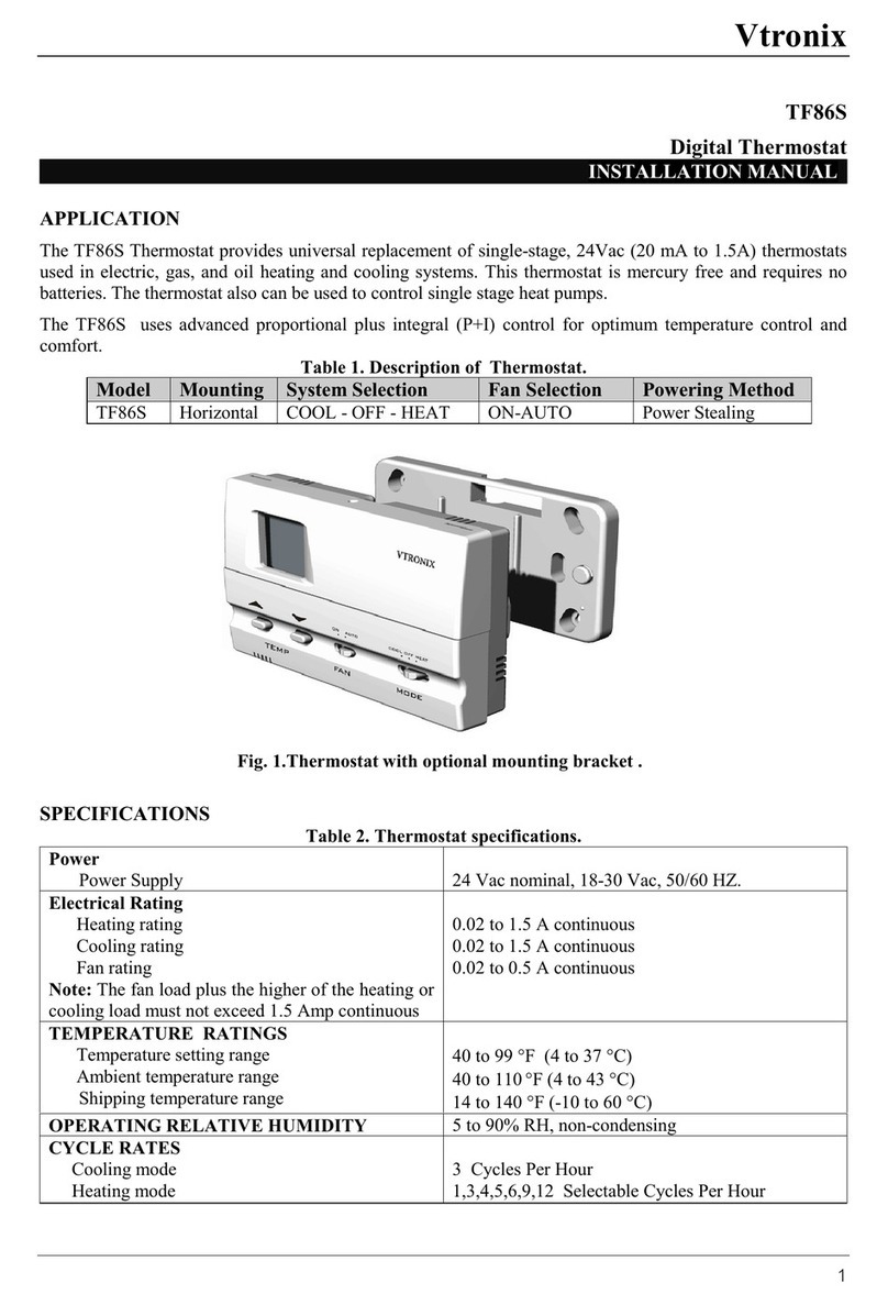
TheTE86S Thermostat provides universalreplacement ofsingle-stage, 24Vac (20 mAto 1.5A) thermostats
used in electric, gas, and oil heatingand coolingsystems. This thermostat is mercuryfreeand requires no
batteries. The thermostat also can be used to control single stage heat pumps.
TheTE86S uses advanced proportionalplus integral (P+I)controlforoptimumtemperature controland
comfort.
Table 1. Description of Thermostat.
Model Mounting SystemSelection Fan Selection Powering
Method
Backlight
TE86SVERTICALCOOL-OFF-HEATON-AUTOPower StealingNo Backlight
TE86SBVERTICALCOOL-OFF-HEATON-AUTOPower StealingBacklight
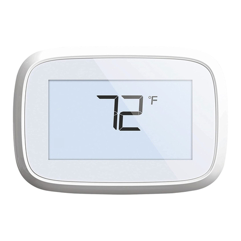
Fig. 1.Thermostat
FEATURES
-Stylish design, replaces Honeywell T834C, White Rodgers 1E56or Lux PSD150.
-LCD displaywith backlightinglit all the time (TE86SB).
-Power stealingfor universal replacement. No common wire required.No batteries.
-Heat cycle rate can be selected (1,3,4,5,6,9,12) bysoftware to suit manyheatingapplications.
-Heating/ coolingdamper output to control either dampers or heat pump reversingvalve.
-User options and set point are retained inthe event of lost power.

Vtronix
2
SPECIFICATIONS
Table 2. Thermostat specifications.
Power
Power Supply24 Vac nominal, 18-30 Vac, 50/60 HZ.
Electrical Rating
Heatingrating
Coolingrating
Fan rating
Note: Thefan load plus the higher of the heatingor
coolingload must not exceed 1.5 Amp continuous
0.02 to 1.5 A continuous
0.02 to 0.5 A continuous
TEMPERATURE RATINGS
Temperature settingrange
Ambient temperature range
Shippingtemperature range
40 to 99 °F (4 to 37 °C)
40 to 110 °F(4 to 43 °C)
14 to 140 °F(-10 to 60 °C)
OPERATING RELATIVE HUMIDITY 5 to 90% RH, non-condensing
CYCLE RATES
Coolingmode
Heatingmode
3 Cycles Per Hour
1,3,4,5,6,9,12 Selectable Cycles Per Hour
DIMENSION
Fig. 2.Thermostat dimension

Vtronix
3
INSTALLATION
Read these instructions thoroughlybefore installing
product. Failureto follow these instructions could
damage the product or cause a hazardous condition.
Checkthe voltage and current ratings on theproduct
to ensure that it is suitable for your application.
Installer must be a trained, experienced service
technician. Checkproduct for proper operation after
installation.
CAUTION
Damage to heating and cooling system may occur.
Disconnect power from the equipment at the main
breaker/fuse block while installing the thermostat.
Mounting Location.
Mount the thermostat approximately5 ft. (1.5m)
above the floor in a location that is free fromdirect
sunlight, heat fromappliances, hot or cold air from
ducts, concealed pipes and chimneys, and drafts or
dead spots behind doors or in corners. Do not mount
on exterior wall, if possible.Failure to locate
thermostat mountingas indicatedwill result in poor
temperature control.
NOTE: Level thermostat mountingis for appearance
onlyand is not required for proper thermostat
operation.
Mounting Thermostat
Take out the backplate byremovingthe locking
screw (if any) at the bottomof the thermostat. Use
flat head screw driver to unlockthe snaps. Lift and
pull it up to remove backplate.
Usingbackplate as a guide,marktwo mounting
holes on the wall. Drill two mountingholes. Place
anchors (provided) into the holes until flush with
the hole. Position backplateon the wall and
thread the wires fromthe heatingand cooling
equipment through the wiringhole. Holdingthe
backplate in place on the wall, secure it to the
wall usingmountingscrews (provided).
Wiring
Pull the connector fromthe backof thermostat by
insertingscrew driver at the base of connector and
gentlylift up.
Fig. 6a.Wiring diagram.
Color-coded 18-22 gauge wire is recommended
for wiring. All wiringmust follow local
electrical code located near each terminal.
Fig. 4.Installing
back plate
Fig. 3.Taking out
back plate
Fig. 5 Lifting the connector

Vtronix
4
Placethe terminal backto the thermostat, make
sure it has the same orientation like inthe picture
described at the back. Snap the thermostat to its
backplate.
Fig. 7. Connecting wire.
Loosen the terminal screw, strip the wire and
connectthe wire as shown in fig7. Firmlytighten
terminal screw when finished.
Set-up switch (E/F)
WARNING
Fire Hazard.
Failure to set theset-up switch to the E position
when electric resistanceheat is used mayresult
in the overheatingof the electric heater elements
due to improper fanoperation.
Theset-up switch is an internal switch (E,F)
located near the wiringterminals. It is used to
select proper fan operation for the heating
systembeingused.
qTheE position is for electricheat and single
stage heat pump applications.
qTheF position is for fuel applications.
Fig. 8. Setup switch.
Fig. 6b. Wiring Diagramfor
single stage heat pump.
HEAT PUMP WITH
HEAT ACTIVE
REVERSING VALVE
HEAT PUMP WITH
COOL ACTIVE
REVERSING VALVE
*Note: Set-up
switch must be
in E position.
*Note: Set-up
switch must be
in E position.
Fig. 9. Installing thermostat.

Vtronix
5
Testing Heating / Cooling Equipment. (OP:01)
While in the installer setup, slide the mode switchto
heat to operatethe heatingequipment or cool to
operate the coolingequipment. The displaywill show
either 00 or 01 on the lower right area and either heat
or cool as selectedbythe mode switch.
a. If the equipment is off, press Ñ keyto turn it on
(if not,checkthe wiringor theequipment).
b. Press
Ñ
keyagain to turn off.
Example displayshowing
Heat equipment is off.
Example displayshowing
Heat equipment is on.
Example displayshowing
Heat equipment is off.
Example displayshowing
Heat equipment is on.
Now follow the followingsteps to change each of the
settings. Each time you press D key, you will advance
to the next operatingparameter. To go backyou must
re-enter the installer set up as described above.
INSTALLER SETUP
Thefollowinginstructions provide information to
test the heating/ coolingequipment and to change
operatingparameters fromthe factorysettings.
Enter Installer Setup
a. Use D or Ñ keyto set the temperature set point
to 52°F(or 11 °C).
Fig. 10. Secure thefront cover.
Secure the thermostat bytighteningthe screw
provided to protect the thermostat fromunwanted
access.
OR
b. Press D
and
Ñ key
simultaneouslyto enter installer
setup.
Setting °C/ °F Indication. (OP:02)
While in the installer setup,
a. Press D key, the displaywill
show °F/°C indication.
b. Press Ñ keyto change °F or °C
indication.
NOTE: Factory setting
is °Findication.

Vtronix
6
NOTE: After return tonormal operation, change
the set point to the desired roomtemperature,
otherwise the default set point ( 70 °F or21°C)
will be used.
Table 4. Recommended cycle rate (CPH).
SYSTEMCPH SETTING
SteamGravity1
Hydronic heat3
Gas or Oilforced air6
Electric heat9
Note: Ifthe equipment manufacture recommends
a different rateuse the ratespecified by the
equipment manufacture.
Setting Heating Cycle Rate. (OP:03)
In cooling, the cycle rate is fixed at 3 Cycles per
hour. To set the cycle rate in heating; while in
installer setup,
a. Press D key, the displaywill
show the heat cycle rate.
b. Press Ñ keyto change the heat
cycle rate to 1,3,4,5,6,9 or 12
cycles per hour.
Note: Thedefault is set at 6cycle per hour.
Table 4 is the recommended cycle rate. The
installer should consult with the heating
equipment manufacturer for proper use.
Setting cooling algorithm. (OP:04)
Thecoolingalgorithmcan be selected as normal or
aggressive. For aggressive, the systemwill cool down
the roomto settingpoint faster than normal algorithm.
However, an overshoot might occurred in some
situations.
a. Press
D
keyto show the cooling
algorithm.
b. Press
Ñ
keyto change algorithm.
0 = Normal algorithm(default).
1 = Aggressive algorithm.
Setting CoolingDelayTime. (OP:05)
In some case there is a necessityto delaythe
operation of the coolingequipment for protection
purpose. While in the installer setup,
a. Press D key. The displaywill
show coolingdelaytime.
b. Press Ñ keyto select the cooling
delaytime (0,3,5 minutes).
NOTE : The default settingis 3
minute.
Configuration Checkout. (OP:06)
Press D key, the current
configuration is displayed.
This information is for factoryuse
only.
Exit Installer Setup.
a. Press D keyagain to save all
settings and exit to the normal
operatingmode.

Vtronix
7
OPERATION
SYSTEM CHECKOUT
Cooling Checkout
WARNING ! Do not operate in cooling mode when the outdoor temperature is below 50 °F ( 10 °C)
otherwise the compressor might be damaged.
1. Slide mode switch toCOOL, O terminal will get energized.
2. Pressing Ñkey to lower the set point below roomtemperature. The star symbol is shown on the display.
If flashing, the compressor delaytime is not yet expired. If lit steady, the compressor is on and terminal
Y is energized.
3. Press D keyuntil set point is higher than roomtemperature. Thestar symbol is removed. The compressor
is off and Y terminal is de-energized.
System Setting
Use mode switch for selectingsystemoperation.
qCool : The thermostat controls the cooling
system.
qHeat :The thermostat controls the heating
system.
qOff : Both heatingand coolingare off.
Fan Setting
Fan switch settings are
On : Fan symbol is indicated on
the display. The fan runs
continuously. Used to improve air
circulation and air quality.
Auto : Fan and Auto symbols are
indicated onthe display.
For coolingmode:
Thefan starts and stops with
coolingequipment.
For heatingmode:
qIf setup switch is at F’position, the fan is
controlled directlybythe heatingequipment.
qIf setup switch is at E’position, the fan starts
and stop with heatingequipment.
MinimumOff Timer
For cooling, when thethermostat
calls for operation whilethe
minimumoff timer is not expired,
the star symbol keeps flashing.
Temperature Setting
Use D or Ñ key to change
temperature settingin a range
of 40 to 99 °F (or 4 to 37 °C).
Thedisplayshows set point
value flashingfor 5 seconds
before returningto the room
temperature.
Back Lighting
( TE86SB )
Thethermostat features
a backlight that will
illuminate all the time.
Theuser can easilysee
the LCD screen under
dimlight situation.

Vtronix
8
Heating Checkout
1. Slide mode switch toHEAT, B terminal will get energized.
2. Press D keyuntil the set pointis higher than roomtemperature. The star symbol is shown on the display.
Theheatingequipment is on and terminal W is energized.
3. Press the Ñkey until set point is lower than roomtemperature. The star symbol is removed. The heating
equipment is off and W terminal is de-energized.
Fan Checkout
1. Slide FAN switch to ON position. The G terminal is energized and the fan should always berunning.
2. Slide FAN switch to AUTO position,
qIn coolingmode, the fan starts and stops with the coolingequipment.
qIn heatingmode when setup switch is in the F position, the fanis controlled directlybythe heating
equipment and maystart a few minutes after the heatingequipment turns on. When setup switchis in the
E position, the fan starts and stops with the heatingequipment.
Application Note
Attached 1000 ohm, 3 watt resistor is used incertain applications to assurecompatibilitywith power stealing
thermostats whereFan does not come ON duringcall for Heat or Cool. Note thatresistor has tobe installed
at the fan terminals and not at thermostat terminals.
To install the Resistor
1. Disconnect power supply.
2. Connect the resistor leads to the terminals
as shown in the drawing.
3. Turn on the system power.
Air Handler Fan Board
1000 Ohm
3Watt
Resistor
Thermostat
C
G
G
VTRONIX, LLC 318 Indian Trace #327, Weston, FL 33326
Copyright 2002 Vtronix Document no. 170306-000E Rev.01
This manual suits for next models
1
Table of contents
Other Vtronix Thermostat manuals