VTS Medical Systems uPC3 3x400V 2x1VFD 2,2kW User manual

EN
VTS reserves the right to implement changes without prior notice
1
Control gear for Supply and Supply-Exhaust
Air Handling Units
The control gear complies with European Standard
IEC 61439-2: Power switchgear and control gear assemblies
ver.1.3 (10.2019)

EN
VTS reserves the right to implement changes without prior notice
2
Table of contents
Table of contents ................................................................................................................................................................................................... 2
SAFETY INSTRUCTIONS AND ALARMS! .................................................................................................................................................................... 3
Technical data ........................................................................................................................................................................................................ 4
Control gear construction ................................................................................................................................................................................. 4
Main internal elements:..................................................................................................................................................................................... 4
Operation parameters ....................................................................................................................................................................................... 4
Short-circuit and overload protection................................................................................................................................................................. 5
Relay pump ....................................................................................................................................................................................................... 5
Control circuit.................................................................................................................................................................................................... 5
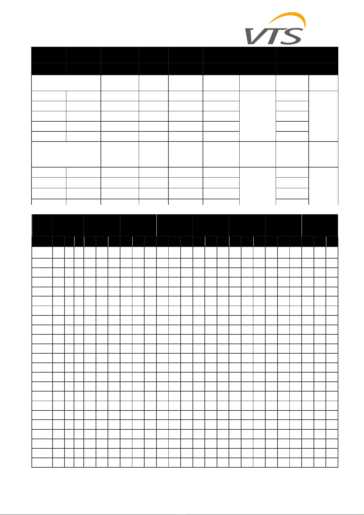
Table I/O (for ver. to 1.0.004)............................................................................................................................................................................. 5
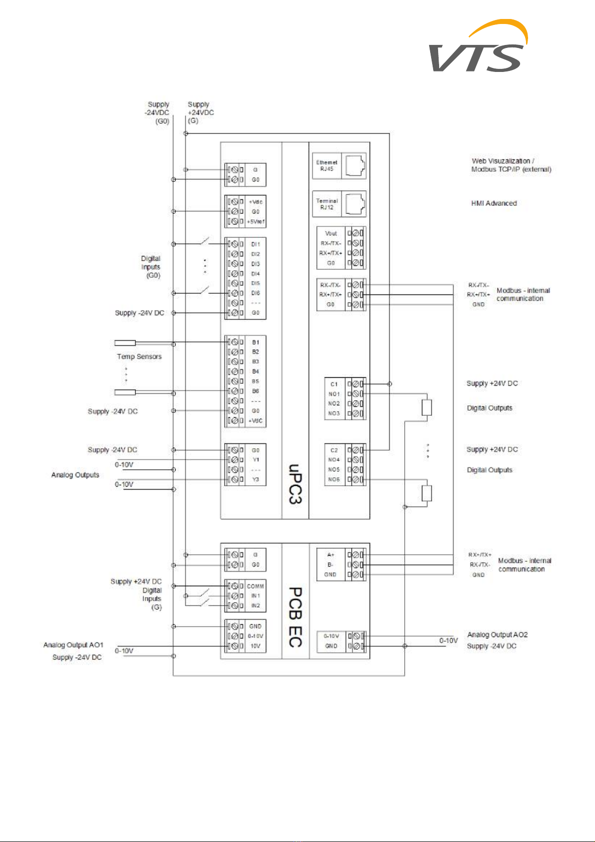
Connection controller diagram........................................................................................................................................................................... 7
Dimensions and weight...................................................................................................................................................................................... 8
Cabling .............................................................................................................................................................................................................. 9
Table A ....................................................................................................................................................................................................... 10
Table B ....................................................................................................................................................................................................... 10
Table B ....................................................................................................................................................................................................... 11
Table B ....................................................................................................................................................................................................... 12
Table C ....................................................................................................................................................................................................... 13
Appendix 1 Circuit diagram of “CBX uPC3 3x400V 2x1VFD <2,2kW” control gear ............................................................................................... 14
Appendix 2 Circuit diagram of “CBX uPC3 3x400V 2x1VFD <11kW” control gear ................................................................................................ 16
Appendix 3 Circuit diagram of “CBX uPC3 3x400V 2x2VFD <11kW” control gear ................................................................................................ 18
Appendix 4 Circuit diagram of “CBX uPC3 3x400V 2x3VFD <11kW” control gear ................................................................................................ 20
Appendix 5 Circuit diagram of “CBX uPC3 3x400V 2x4VFD <11kW, 2x5VFD <7,5kW” control gear ...................................................................... 22
Appendix 6 Circuit diagram of “CBX uPC3 3x400V 1x1VFD <11kW” control gear ................................................................................................ 24
Appendix 7 Circuit diagram of control circuit .................................................................................................................................................... 25

EN
VTS reserves the right to implement changes without prior notice
3
SAFETY INSTRUCTIONS AND ALARMS!
Prior to installation and use of the unit, please read this Manual carefully. Installation, connection and maintenance shall be executed by a qualified
specialist considering the local rules, normative acts and practice. Prior to connecting peripherals to the board, please read the Manual. The Company
shall not assume any liability for personal injuries or damage to property in case of failure to observe these safety requirements, if the product is
modified without manufacturer’s consent
Electrical power switching and unit maintenance shall be performed only by qualified employee following the manufacturer manual and applicable
safety instructions.
To reduce a potential risk during maintenance or installation works appropriate safety clothes shall be worn.
Electrical power to power mains must be connected via appropriate rating circuit-breaker.
All control gears need to be powered from the main switchgear equipped with appropriate protection of wires powering the control box.
Assembly, wiring and start-up of the control gear should by done by qualified staff only.
For applications subject to strong vibrations (1.5 mm pk-pk 10/55 Hz), secure the cables connected to the μPC using clamps placed around
3 cm from the connectors.
The entire length of the input/output connections must be less than 30 m, according to EN 61000-6-2.
Installation must be performed according to the standards and legislation in force in the country where the appliance is used.
In the event of malfunctions do not attempt to repair the controller, but rather contact the service.
Without additional elements the control gears can work inside a building. Assembly outside in a moderate climate is permissible if an additional
heating module is assembled.

EN
VTS reserves the right to implement changes without prior notice
4
Technical data
Control gear construction
Casing with external mains switch and RJ11 port for connecting the HMI Advanced control panel
Main internal elements:
short-circuit and overload protection assemblies
connection units
CAREL µPC3 XS controller
Operation parameters
System TN
U3 rated power supply voltage: ~230V / 3N~400V
Ui rated insulation voltage : 400V
Uimp rated impulse withstand voltage: 2,5kV
Rated short-time withstand current Icw for respective circuits - effective
value of alternating current component withstood during 1 second, i.e.:
short-circuit current expected at rated connecting voltage: 6kA
Rated peak withstand current (ipk) at cosφ= 0.5: 10,2kA
rated short-circuit current: 6kA
coincidence factor 0.9: 0,9
rated frequency: 50..60Hz ±1Hz
protection class: IP54
acceptable operating temperature: 0÷40°C
supply voltage of control circuits: 24V DC
EMC environment: 1

EN
VTS reserves the right to implement changes without prior notice
5
Short-circuit and overload protection
Supply VFD, EC motors 1F1M – 1F5M (gG32A)
Exhaust VFD, EC motors 2F1M – 2F5M (gG32A)
Water pump, rotary wheel drive F1 (B6)
Lighting circuit F2 (B6)
Control signal protection 230Vac F3 (2,5A)
Control signal protection 24Vdc F4 (2,5A)
Relay pump
Pump K1
Control circuit
Relay outputs
(NO1, NO2, NO3) – C1; (NO4, NO5, NO6)-C2; NO7-C7
Analog inputs
(B1, B2, B3, B4, B5, B6) – GND
Analog outputs
(Y1, Y3) - GND; (AO1, AO2) -GND
Digital inputs
(DI1, DI2, DI3, DI4, DI5, DI6) – GND
Communication protocol
RS485 (ModBus Master); Modbus TCP/IP
Table I/O (for application ver. to 1.0.004)
UPC3 UPC3
Supply Analog Inputs
G +24V DC B1 Temp. Supply
G0 -24V DC B2 Temp. Return (Room) / PreHeater (for Compact AHU)
Digital Inputs B3 Temp. External
DI1 Fire Alarm B4 Temp. Exhaust
DI2 Heater Alarm / DXH Alarm B5 Temp. Water Heater
DI3 Cooler Alarm B6 Temp. Recovery on Supply / PreHeater (for Ventus AHU)
DI4 Humidity Alarm / Filter supply alarm Analog Outputs
DI5 Summer – Winter / Filter return alarm Y1 Heater / DXH
DI6 Remote STOP Y3 Recovery / Mixing damper / Cooler
Relay Outputs Communication
NO1 Heater / DXH 1st. Ethernet RJ-45 Web Visualization / Modbus TCP/IP (external)
NO2 Dampers RS-485 Modbus RTU Master (internal)
NO3 Global Alarm / ReHeater / PreHeater pLan HMI Advanced – pGD1
NO4 Cooler
NO5 Cooler 2 / DXH Reverse / Humidity / Glicol pump / Redundant
NO6 Heater 2 / DXH 2 st.
PCB EC PCB EC
Supply Digital Inputs
24V +24V DC IN1 Supply Filter
24V -24V DC IN2 Return Filter
Analog Outputs Communication
AO1 -
AIN
10V
Recovery RS-485 Modbus RTU Slave (internal)
AO2-
AOUT
0-10V
Mixing

EN
VTS reserves the right to implement changes without prior notice
6
Table I/O (for application ver. to 1.0.005)
UPC3 UPC3
Supply Analog Inputs
G +24V DC B1 Temp. Supply
G0 -24V DC B2 Temp. Return (Room) / PreHeater (for Compact AHU)
Digital Inputs B3 Temp. External
DI1 Fire Alarm B4 Temp. Exhaust
DI2 Heater Alarm / DXH Alarm B5 Temp. Water Heater
DI3 Cooler Alarm / DXH Alarm B6 Temp. Recovery on Supply / PreHeater (for Ventus AHU)
DI4 Humidity Alarm / Filter supply alarm Analog Outputs
DI5 DX_H reverse / Filter return alarm Y1 Recovery / Mixing damper / Heater / Re-Heater for DX_H
DI6 Remote STOP Y3 Recovery / Mixing damper / Cooler / DX_H
Relay Outputs Communication
NO1 Heater / Re-Heater for DX_H Ethernet RJ-45 Web Visualization / Modbus TCP/IP (external)
NO2 Dampers RS-485 Modbus RTU Master (internal)
NO3 Global Alarm / ReHeater / PreHeater pLan HMI Advanced – pGD1
NO4 Cooler / DX_H
NO5 Cooler 2 / Humidifier / Glycol / Redundant / DX_H reverse
NO6 Heater 2 / DX_H st. 2 / Humidifier
PCB EC PCB EC
Supply Digital Inputs
24V +24V DC IN1 Supply Filter alarm
24V -24V DC IN2 Return Filter alarm
Analog Outputs Communication
AO1 -
AIN
10V
Recovery / Humidifier RS-485 Modbus RTU Slave (internal)
AO2-
AOUT
0-10V
Recovery / Mixing dampers / Re-Heater / Pre-Heater

EN
VTS reserves the right to implement changes without prior notice
7
Connection controller diagram

EN
VTS reserves the right to implement changes without prior notice
8
Dimensions and weight
CBX NAME Weight [kg] Dimensions (w x h x d)
uPC3 3x400V 2x1VFD <2,2kW 3,85 390x317x150
uPC3 3x400V 2x1VFD <11kW 4,1 390x317x150
uPC3 3x400V 2x2VFD <11kW 5,0 540x317x150
uPC3 3x400V 2x3VFD <11kW 8,4 657x455x160
uPC3 3x400V 2x4VFD <11kW, 2x5VFD <7,5kW 9,1 693x455x160
3x400V 1x1VFD <11kW 3,95 390x317x150

EN
VTS reserves the right to implement changes without prior notice
9
Cabling
Connect power leads of the control gear and
frequency converter of the fan drive according to
the Electric diagram.
The wire cross-sections have been selected for long
term current capacity for cables arranged in the air
(supported on brackets, cable racks, in perforated trays) with
spacing from the wall of min. 0.3 cable diameter, insulated with PVC,
for 3-conductors loaded.
Due to the protection selectivity, length, cable placement method
and short-circuit currents, revise the feeders’ cross-sections in the
table below.
Type Picture Ddescription Parameters
[1] Control wires with
copper cores with
a shield. PVC
isolation.
Nominal voltage:
300/500 V
Ambient
temperature: –30
to 80°C
[2]
Copper cores. PVC
isolation.
Nominal voltage:
450/750V
Ambient
temperature:
from –40 to 70°C
[3]
Copper cores. PVC
isolation.
Nominal voltage:
150 V
Ambient
temperature: –
20…60°C
[4]
Flat
communication
cable without
shield.
Nominal voltage:
150V
Ambient
temperature: –
20…60°C
Name of element Symbol Type Name of element
Analog Inputs B1-B6 [1] 2x0,5
Analog Outputs
Y1,Y3,
Ain10V,
Aout0-
10V
[1] 3x0,5
Digital Inputs
DI1-DI6,
IN1,IN2
[2] 2x0,5
Relay Outputs NO2-NO6 [2] 2x0,5
HMI Basic UPC –
reduced function
interface
RS-485 [3] UTP 1x2
HMI Advanced UPC
– full function
interface
N3 [4] 8x0,1
HW circulating
pump contactor K1 [2] 3x1,5

EN
VTS reserves the right to implement changes without prior notice
10
Table A
EN
Table B
Motor
power
[kW]
0,55kW
0,75kW
1,1kW
1,5kW
2,2kW
3kW
4kW
5,5kW
L1 L2
L3
L1 L2 L3 L1 L2 L3 L1 L2 L3 L1 L2 L3 L1 L2 L3 L1 L2 L3 L1 L2 L3
only supply
14,5
15,5
17,5
18,5
21,5
8,0 7,5 13,0
10,0
9,5 15,0
13,0
12,5
18,0
0,55kW 19,0
0,75kW 20,0
21,0
1,1kW 22,0
23,0
25,0
1,5kW 23,0
24,0
26,0
27,0
2,2kW 26,0
27,0
29,0
30,0
33,0
3kW 12,5
10,0
13,0
14,0
10,0
13,0
15,5
10,0
13,0
17,5
10,0
13,0
14,0
13,5
19,0
4kW 14,5
12,0
15,0
16,0
12,0
15,0
18,5
12,0
15,0
19,5
12,0
15,0
16,0
15,5
21,0
18,0
17,5
23,0
5,5kW 17,5
15,0
18,0
18,0
15,0
18,0
20,2
15,0
18,0
22,5
15,0
18,0
19,0
18,5
24,0
21,0
20,5
26,0
24,0
23,5
29,0
7,5kW 21,5
19,0
22,0
23,0
19,0
22,0
24,5
19,0
22,0
26,5
19,0
22,0
23,0
22,5
28,0
25,0
24,5
30,0
28,0
27,5
33,0
11kW 27,5
25,0
28,0
29,0
25,0
28,0
30,5
25,0
28,0
32,5
25,0
28,0
29,0
28,5
34,0
31,0
30,5
36,0
34,0
33,5
39,0
2x4kW 24,0
23,5
29,0
26,0
25,5
31,0
29,0
28,5
34,0
2x5,5kW 30,0
29,5
35,0
32,0
31,5
37,0
35,0
34,5
40,0
2x7,5kW 38,0
37,5
43,0
40,0
39,5
45,0
43,0
42,5
48,0
2x11kW 50,0
49,5
55,0
52,0
51,5
57,0
55,0
54,5
60,0
3x4kW
3x5,5kW
3x7,5kW
3x11kW
4x4kW
4x5,5kW
4x7,5kW
4x11kW
Motor rated
power
Motor rated
current FC protection FC supply
cable Motor cable Control gear power supply cable Control gear rated current
[kW] [A] [mm2] [mm2] [mm2] [A]
3~230V / 50Hz 1~230V / 50Hz supply AHU
1~230V
supply- exhaust
1~230V supply AHU L1
supply-
exhaust L1
0,55 2,5 gG10 3x1,5 4x1 3x1,5
3 x TABLE C
14,5
TABLE B
0,75 3,0 gG10 3x1,5 4x1,5 3x1,5 15,5
1,1 4,5 gG10 3x1,5 4x1,5 3x1,5 17,5
1,5 6,0 gG20 3x2,5 4x1,5 3x2,5 18,5
2,2 8,0 gG20 3x2,5 4x1,5 3x2,5 21,5
3x400V / 50Hz 3x400V / 50Hz supply AHU
3~400V
supply- exhaust
3~400V
supply AHU L1 /
L2 / L3
supply-
exhaust
L1 / L2 / L3
3,0 6,0 gG16 4x2,5 4x2,5 5x1,5
5 x TABLE C
8 / 7,5 / 13
TABLE B
4,0 8,0 gG16 4x2,5 4x2,5 5x1,5 10 / 9,5 / 15
5,5 11,0 gG20 4x2,5 4x2,5 5x2,5 13 / 12,5 / 18

EN
VTS reserves the right to implement changes without prior notice
11
Table B
Motor
power
[kW]
7,5kW
11kW
2x4kW
2x5,5kW
2x7,5kW
2x11kW
3x4kW
3x5,5kW
L1 L2 L3 L1 L2 L3 L1 L2 L3 L1 L2 L3 L1 L2 L3 L1 L2 L3 L1 L2 L3 L1 L2 L3
only supply
17,0
16,5
22,0
23,0
22,5
28,0
18,0
17,5
23,0
24,0
23,5
29,0
32,0
31,5
37,0 44,0 43,5 49,0 26,0
25,5 31,0
35,0
34,5
40,0
0,55kW
0,75kW
1,1kW
1,5kW
2,2kW
3kW
4kW
5,5kW
7,5kW 32,0
31,5
37,0
11kW 38,0
37,5
43,0
44,0
43,5
49,0
2x4kW 33,0
32,5
38,0
39,0
38,5
44,0
34,0
33,5
39,0
2x5,5kW 39,0
38,5
44,0
45,0
44,5
50,0
40,0
39,5
45,0
46,0
45,5
51,0
2x7,5kW 47,0
46,5
52,0
53,0
52,5
58,0
48,0
47,5
53,0
54,0
53,5
59,0
62,0
61,5
67,0
2x11kW 59,0
58,5
64,0
65,0
64,5
70,0
60,0
59,5
65,0
66,0
65,5
71,0
74,0
73,5
79,0 86,0 85,5 91,0
3x4kW 42,0
41,5
47,0
48,0
47,5
53,0
56,0
55,5
61,0 68,0 67,5 73,0 50,0
49,5 55,0
3x5,5kW 51,0
50,5
56,0
57,0
56,5
62,0
65,0
64,5
70,0 77,0 76,5 82,0 59,0
58,5 64,0
68,0
67,5
73,0
3x7,5kW 63,0
62,5
68,0
69,0
68,5
74,0
77,0
76,5
82,0 89,0 88,5 94,0 71,0
70,5 76,0
80,0
79,5
85,0
3x11kW 81,0
80,5
86,0
87,0
86,5
92,0
95,0
94,5
100,0
107,0
106,5
112,0
89,0
88,5 94,0
98,0
97,5
103,0
4x4kW 58,0
57,5 63,0
67,0
66,5
72,0
4x5,5kW 70,0
69,5 75,0
79,0
78,5
84,0
4x7,5kW 86,0
85,5 91,0
95,0
94,5
100,0
4x11kW 110,0
109,5
115,0
119,0
118,5
124,0
EN

EN
VTS reserves the right to implement changes without prior notice
12
Table B
Motor
power
[kW]
3x7,5kW
3x11kW
4x4kW
4x5,5kW
4x7,5kW
4x11kW
L1 L2 L3 L1 L2 L3 L1 L2 L3 L1 L2 L3 L1 L2 L3 L1 L2 L3
only supply
47,0 46,5 52,0 65,0 64,5 70,0 34,0 33,5 39,0 46,0 45,5 51,0 62,0 61,5 67,0 86,0 85,5 91,0
0,55kW
0,75kW
1,1kW
1,5kW
2,2kW
3kW
4kW
5,5kW
7,5kW
11kW
2x4kW
2x5,5kW
2x7,5kW
2x11kW
3x4kW
3x5,5kW
3x7,5kW 92,0 91,5 97,0
3x11kW 110,0
109,5
115,0
128,0
127,5
133,0
4x4kW 79,0 78,5 84,0 97,0 96,5 102,0
66,0 65,5 71,0
4x5,5kW 91,0 90,5 96,0 109,0
108,5
114,0
78,0 77,5 83,0 90,0 89,5 95,0
4x7,5kW 107,0
106,5
112,0
125,0
124,5
130,0
94,0 93,5 99,0 106,0
105,5
111,0
122,0
121,5
127,0
4x11kW 131,0
130,5 136,0 149,0 148,5
154,0 118,0
117,5
123,0 130,0
129,5 135,0
146,0 145,5
151,0
170,0 169,5
175,0

EN
VTS reserves the right to implement changes without prior notice
13
Table C
Motor power
[kW]
0,55kW
0,75kW
1,1kW
1,5kW
2,2kW
3kW
4kW
5,5kW
7,5kW
11kW
2x4kW
2x5,5kW
2x7,5kW
2x11kW
3x4kW
3x5,5kW
3x7,5kW
3x11kW
4x4kW
4x5,5kW
4x7,5kW
4x11kW
1,5 1,5 1,5 2,5 2,5 1,5 1,5 2,5 2,5 4 2,5 4 6 10 4 6 10 16 6 10 16 25
0,55kW 2,5
0,75kW 2,5 2,5
1,1kW 2,5 2,5 2,5
1,5kW 2,5 2,5 4 4
2,2kW 4 4 4 4 4
3kW 1,5 1,5 2,5 2,5 2,5
4kW 1,5 2,5 2,5 2,5 2,5 2,5
5,5kW 2,5 2,5 2,5 2,5 2,5 4 4
7,5kW 2,5 2,5 4 4 4 4 4 6
11kW 4 4 4 6 6 6 6 10 10
2x4kW 4 4 6 6 10 6
2x5,5kW 6 6 6 10 10 10 10
2x7,5kW 10 10 10 10 10 10 10 16
2x11kW 10 10 16 16 16 16 16 16 25
3x4kW 10 10 16 16 10
3x5,5kW 10 16 16 25 16 16
3x7,5kW 16 16 25 25 16 25 25
3x11kW 25 25 25 16 (2x) 25 16 (2x) 16 (2x) 25 (2x)
4x4kW 16 16 25 16 (2x) 16
4x5,5kW 16 25 25 16 (2x) 25 25
4x7,5kW 25 25 16 (2x) 25 (2x) 25 16 (2x) 25 (2x)
4x11kW
25 (1x)
10 (1x)
25 (1x)
10 (1x)
25 (2x) 35 (2x)
25 (1x)
10 (1x)
25 (2x) 25 (2x) 35 (2x)

EN
VTS reserves the right to implement changes without prior notice
14
Appendix 1 Circuit diagram of “CBX uPC3 3x400V 2x1VFD <2,2kW” control gear
2x1 motors 1x230V / 3x400V from 0,75kW to 2,2kW

EN
VTS reserves the right to implement changes without prior notice
15

EN
VTS reserves the right to implement changes without prior notice
16
Appendix 2 Circuit diagram of “CBX uPC3 3x400V 2x1VFD <11kW” control gear
2x1 3x400V from 0,75kW to 11kW

EN
VTS reserves the right to implement changes without prior notice
17

EN
VTS reserves the right to implement changes without prior notice
18
Appendix 3 Circuit diagram of “CBX uPC3 3x400V 2x2VFD <11kW” control gear
2x2 motors 3x400V from 0,75kW to 11kW

EN
VTS reserves the right to implement changes without prior notice
19

EN
VTS reserves the right to implement changes without prior notice
20
Appendix 4 Circuit diagram of “CBX uPC3 3x400V 2x3VFD <11kW” control gear
2x3 motors 3x400V from 0,75kW to 11kW
This manual suits for next models
7
Table of contents
Other VTS Medical Systems Control Unit manuals
Popular Control Unit manuals by other brands

Texas Instruments
Texas Instruments CDCM1804 user guide

Emerson
Emerson SAPAG 8400 Series Installation and maintenance instruction

Smarteh
Smarteh LPC-2.CX1 user manual

ABB
ABB ACS880-04 drive modules Hardware manual

Optical Systems Design
Optical Systems Design OSD361 Operator's manual

DMP Electronics
DMP Electronics 893A installation guide