VTS Medical Systems ventus VS 10-75 CG UPC User manual

Control gear for Supply and Supply-Exhaust
Air Handling Units
Operation and Maintenance Manual
EN
DTR - CG UPC - ver.2.6 (06.2019)

www.vtsgroup.com
The control gear complies with European Standard
IEC/EN 60439-1 + AC Standard Switchboards and low-voltage control gears
EN

EN
VTS reserves the right to implement changes without prior notice
User’s Manual 1
Table of Content
I. USER’S MANUAL............................................................................................ 3
1. DESCRIPTION OF CONTROLS............................................................................................................................................3
1.1. INTRODUCTION.................................................................................................................................................................3
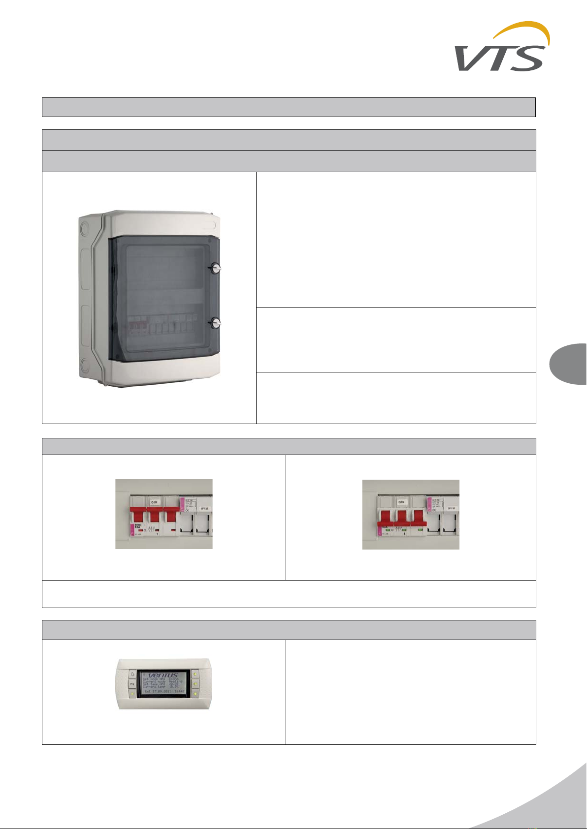
1.2. MAINS SWITCH..................................................................................................................................................................3
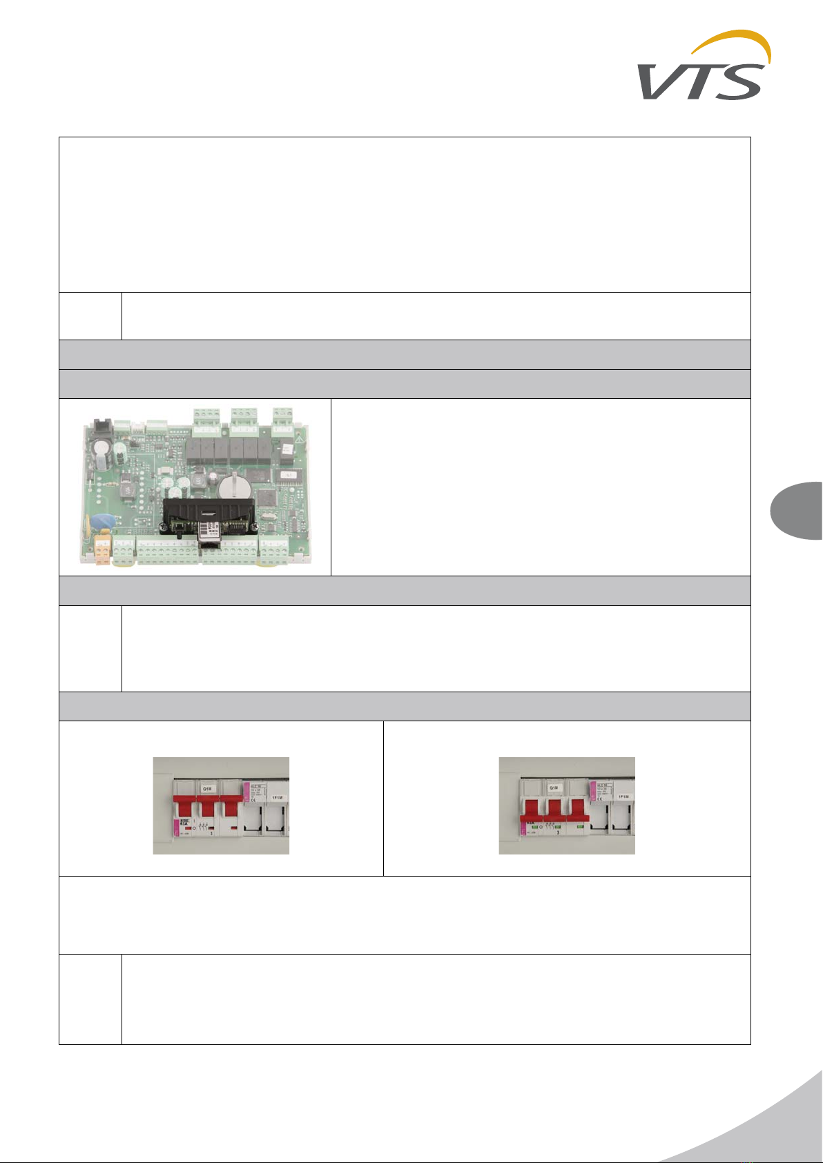
1.3. COMMUNICATION PORT...................................................................................................................................................3
1.4. SIGNALLING CONTROLLER STATUS...............................................................................................................................4
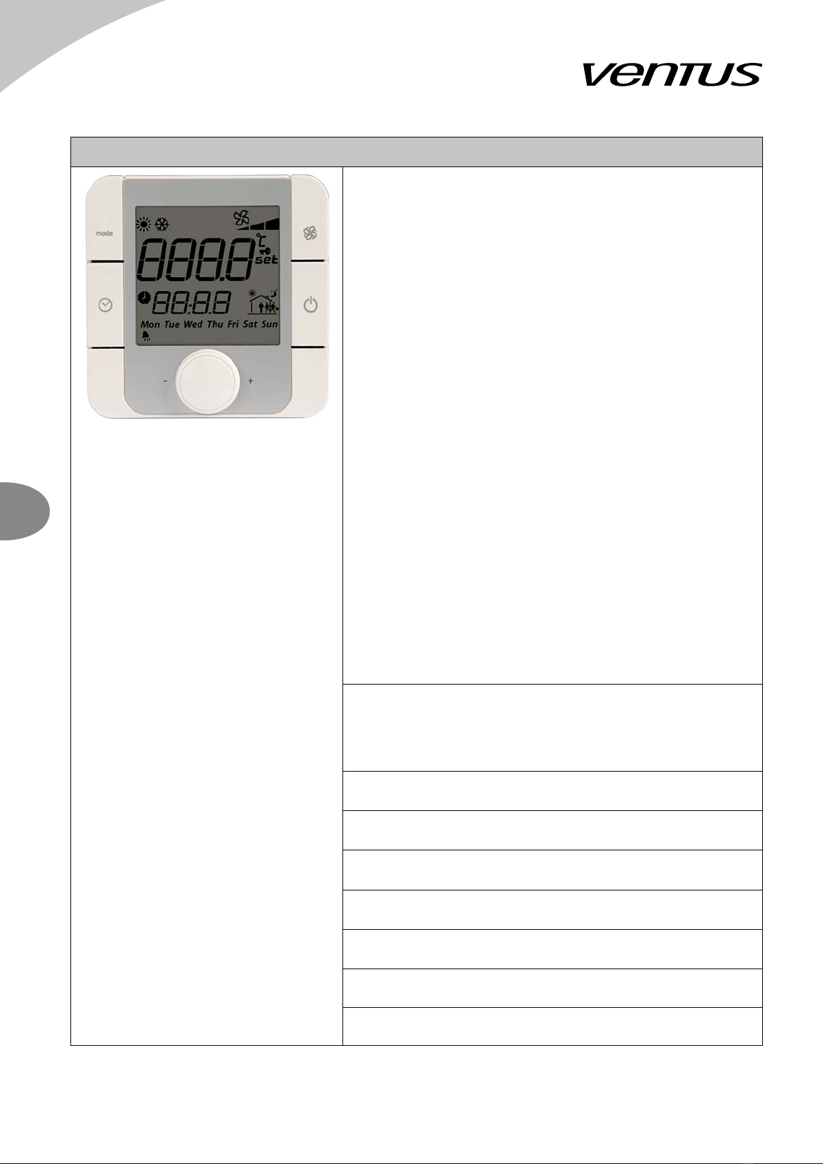
1.5. ADVANCED CONTROL PANEL VS 00 HMI ADVANCED UPC ..........................................................................................4
1.6. SIMPLIFIED CONTROL PANEL - HMI BASIC UPC ...........................................................................................................6
WEB-SERVER OPTION – AVAILABLE AS EXPANSION CARD ...............................................................................................7
MODBUS TCP/IP – AVAILABLE AS EXPANSION CARD ..........................................................................................................7
2. SYSTEM START-UP ..............................................................................................................................................................7
2.1. SWITCHING ON POWER SUPPLY ....................................................................................................................................7
2.2. HMI ADVANCED UPC.........................................................................................................................................................8
2.3. LANGUAGE SELECTION ...................................................................................................................................................9
2.4. ENTERING THE PASSWORD ............................................................................................................................................9
2.5. SELECTION OF OPERATING MODE ................................................................................................................................9
2.6. INDICATION OF OPERATING MODE ..............................................................................................................................10
3. SYSTEM OPERATION ........................................................................................................................................................ 11
3.1. PARAMETERS OPERATING MODE............................................................................................................................ 11
3.2. CALENDAR MAIN PAGE.............................................................................................................................................. 11
3.2.1. CALENDAR MONDAY...............................................................................................................................................12
3.2.2. CALENDAR SPECIAL ...............................................................................................................................................12
3.2.3. CALENDAR EXCEPTIONS .......................................................................................................................................12
3.3. CALENDAR MODE IN HMI BASIC ...................................................................................................................................13
3.4. PARAMETERS AIR TEMPERATURES ........................................................................................................................14
3.4.1. PARAMETERS HUMIDITY........................................................................................................................................14
3.4.2. PARAMETERS HUMIDITY CONTROL......................................................................................................................14
3.4.3. PARAMETERS SUP FAN & DAMPER ......................................................................................................................14
3.4.4. PARAMETERS EXH FAN & DAMPER ......................................................................................................................15
3.4.5. PARAMETERS HEATING..........................................................................................................................................15
3.4.6. PARAMETERS RECOVERY .....................................................................................................................................16
3.4.7. PARAMETERS COOLING.........................................................................................................................................16
3.4.8. PARAMETERS PRE-HEATING .................................................................................................................................17
3.4.9. PARAMETERS SUP MOTORS .................................................................................................................................17
3.4.10. PARAMETERS EXH MOTORS ............................................................................................................................... 17
3.4.11. PARAMETERS SUPPLY PRESSURE TRANSDUCER ........................................................................................... 17
3.4.12. PARAMETERS EXHAUST PRESSURE TRANSDUCER........................................................................................17
3.4.13. PARAMETERS SUPPLY PRESSURE TRANSDUCER...........................................................................................18
3.4.14. PARAMETERS EXHAUST PRESSURE TRANSDUCER........................................................................................18
3.4.15. PARAMETERS REDUNDAN...................................................................................................................................18
3.5. SETTINGS TIMERS .....................................................................................................................................................18
3.5.1. SETTINGS STANDBY ...............................................................................................................................................18
3.5.2. SETTINGS NIGHT COOLING ...................................................................................................................................19
3.5.3. SETTINGS NIGHT TEST...........................................................................................................................................19
3.5.4. SETTINGS FAST HEATING ......................................................................................................................................19
3.5.5. SETTINGS TEMPERATURES...................................................................................................................................19
3.5.6. SETTINGS HUMIDITY CONTROL............................................................................................................................20
3.5.7. SETTINGS FANS ......................................................................................................................................................20
3.5.8. SETTINGS WATER HEATER....................................................................................................................................21
3.5.9. SETTINGS INIT HEATING ........................................................................................................................................21
3.5.10. SETTINGS RECOVERY UNIT ................................................................................................................................22
3.5.11. SETTINGS DX COOLER.........................................................................................................................................22
3.5.12. SETTINGS WATER PRE-HEATER .........................................................................................................................23
3.5.13. SETTINGS INIT HEATING ......................................................................................................................................23
3.5.14. SETTINGS FAN PI REGULATOR ...........................................................................................................................23
3.5.15. SETTINGS PRESSURE PI REGULATORS ............................................................................................................24
3.5.16. SETTINGS TEMP PI REGULATORS ......................................................................................................................24
3.5.17. SETTINGS MANUAL MODE ...................................................................................................................................25

EN
VTS reserves the right to implement changes without prior notice
User’s Manual
2
3.5.18. SETTINGS INPUT OFFSET....................................................................................................................................26
3.5.19. SETTINGS FREQ CONV RRG ...............................................................................................................................26
3.5.20. SETTINGS FANS FIRE MODE ...............................................................................................................................27
3.5.21. SETTINGS UNIVERSAL REGULATOR...................................................................................................................27
EXAMPLE 1 – Additional roof exhaust fan ...............................................................................................................................28
3.6. ALARM MENU...................................................................................................................................................................29
ALARMING IN HMI BASIC.......................................................................................................................................................29
II. ADVANCED MANUAL.................................................................................. 31
4. SERVICE MENU ..................................................................................................................................................................31
4.1. SERVICE MENU CONFIG PAGES ..............................................................................................................................31
4.2. SERVICE MENU OUTPUTS ........................................................................................................................................37
FRQ CONVERTERS CONFIGURATION .................................................................................................................................37
4.4. SYSTEM INFO ..................................................................................................................................................................38
5. CONTROL ALGORITHMS...................................................................................................................................................38
6. TECHNICAL DATA ..............................................................................................................................................................41
7. CABLING ............................................................................................................................................................................. 43
Appendix 1 Circuit diagram of VS 10-75 CG UPC control gear 1/2 .............................................................................................
49
Appendix 1 Circuit diagram of VS 10-75 CG UPC control gear 2/2 .............................................................................................
50
Appendix 2 Circuit diagram of VS 40-150 CG UPC SUP control gear 1/2............................................................................... 51
Appendix 2 Circuit diagram of VS 40-150 CG UPC SUP control gear 2/2............................................................................... 52
Appendix 3 Circuit diagram of VS 40-150 CG UPC SUP-EXH control gear 1/2 ..........................................................................
53
Appendix 3 Circuit diagram of VS 40-150 CG UPC SUP-EXH control gear 2/2 ..........................................................................
54
Appendix 4 Circuit diagram of VS 180-300 CG UPC control gear 1/3 .....................................................................................55
Appendix 4 Circuit diagram of VS 180-300 CG UPC control gear 2/3 .....................................................................................56
Appendix 4 Circuit diagram of VS 180-300 CG UPC control gear 3/3 .....................................................................................57
Appendix 5 Circuit diagram of VS 400-650 CG UPC control gear 1/4 .....................................................................................58
Appendix 5 Circuit diagram of VS 400-650 CG UPC control gear 2/4 .....................................................................................59
Appendix 5 Circuit diagram of VS 400-650 CG UPC control gear 3/4 .....................................................................................60
Appendix 5 Circuit diagram of VS 400-650 CG UPC control gear 4/4 .....................................................................................61
Appendix 6 Circuit diagram of power and motor connection VS 10-75 CG UPC control gears ...............................................62
Appendix 7 Circuit diagram of power and motor connection for VS 40-150 CG UPC SUP control gear .................................62
Appendix 8 Circuit diagram of power and motor connection VS 40-150 CG UPC SUP-EXH control gear
(used also for VS 180-300 supply) ...........................................................................................................................................63
Appendix 9 Circuit diagram of power and motor connection for VS 180-300 CG UPC control gear
(used also for VS 400-650 supply) ...........................................................................................................................................64
Appendix 10 Circuit diagram of power and motor connection VS 400-650 CG UPC control gear........................................... 65
Appendix A Circuit diagram of motor connection depending on the type of the frequency converter ...................................... 66
Appendix 11 The application control schemes .........................................................................................................................66

EN
VTS reserves the right to implement changes without prior notice
User’s Manual 3
I. USER’S MANUAL
1. DESCRIPTION OF CONTROLS
1.1. INTRODUCTION
Application:
Protection and control of supply and exhaust AHUs
equipped with up to:
two fan sets (up to 8 fans in total) and two air
dampers
cooler, heater, heat recovery system
optional pre-heater (in specified units)
three filtration sections
Range of operation:
VS 10-75 CG UPC
VS 40-150 CG UPC SUP
VS 40-150 CG UPC SUP-EXH
VS 180-300 CG UPC
VS 400-650 CG UPC
Systems equipped with frequency converters and motors
with up to 11kW power output
1.2. MAINS SWITCH
Function:
Swithing the control gear On / Off
1.3. COMMUNICATION PORT
RJ11 socket, is placed In front of the control gear
housing
Function:
Connecting the HMI Advanced UPC control panel
to the controller

EN
VTS reserves the right to implement changes without prior notice
User’s Manual
4
1.4. SIGNALLING CONTROLLER STATUS
In the bottom left side of the controller, there are two LED indicators
Orange LED indicates the condition of the power supply. LED off
means no power supplied to the terminals or malfunction of internal
power supply circuitry. LED on means correct parameters of the
power supply.
Green LED indicates the condition of controller's BIOS. LED off
means that the firmware is not running correctly. LED on means that
BIOS runs OK and the controller is ready for operation.
!
1. All control gears of the VS…CG UPC typeline need to be powered from the main
switchgear equipped with appropriate protection of wires powering the control box.
2. Assembly, wiring and start-up of the control gear should by done by qualified staff
only.
3. For applications subject to strong vibrations (1.5 mm pk-pk 10/55 Hz), secure the cables
connected to the PC using clamps placed around 3 cm from the connectors.
4. The entire length of the input/output connections must be less than 30 m, according to EN
61000-6-2.
5. Installation must be performed according to the standards and legislation in force in the
country where the appliance is used.
6. In the event of malfunctions do not attempt to repair the controller, but rather contact the
service.
Without additional elements the control gears can work inside a building. Assembly outside
in a moderate climate is permissible if an additional heating module is assembled. The
X0:3,N clamps are designed to power that module. (ratings: 230V AC, 6A)
1.5. ADVANCED CONTROL PANEL VS 00 HMI ADVANCED UPC
LCD Display
Displaying available parameters, settings and current values
BELL Button
Jump to alarm handling pages
PRG Button
1. Quick jump to the Calendar main page
2. In Calendar pages - quick clear of the settings
ESC Button
Jump to the main page or leaving the parameter change
UP Arrow
1. Moving up accross the menu screens (when the cursor stays in
upper left corner)
2. Increasing the parameter value

EN
VTS reserves the right to implement changes without prior notice
User’s Manual 5
ENTER Button
1. Moving the cursor across the screen - cursor jumps to the
next parameter available for changing. Read-Only parameters
are not marked with the cursor.
2. Confirming entered values
3. Entering sub-menus from the main menu level:
Parameters
Calendar
Alarms
Settings
Service
DOWN Arrow
1. Moving down accross the menu screens (when the cursor
stays in upper left corner)
2. Decreasing the parameter value
Navigation example:
1. In the main menu level use UP/DOWN arrows to find the desired sub-menu
2. Press ENTER to go to the sub-menu level
3. Use UP/DOWN arrows to move accross the sub-menu screens
4. In the desired screen, use the ENTER button to switch between the changeable parameters - the
ursor starts from the upper left corner (which is the base positnion) and jumps on and on until going
back to the upper left corner - then the loop can be started again
5. To change the parameter marked with the cursor, use the UP/DOWN arrows
6. Press ENTER to go confirm the change and to jump further
Functions:
Air handling unit operation, parameterization and maintenance
Selection of control application
Time zones setting
Displaying and canceling alarm statuses, viewing alarm history
!
Parameters available in the LCD window depends on a AHU type and the control
application. Hence in AHUs not equipped with heater, options related to the heating module
will not be visible.
HMI Advanced UPC can’t serve as a room temperature sensor.
Optional element

EN
VTS reserves the right to implement changes without prior notice
User’s Manual
6
1.6. SIMPLIFIED CONTROL PANEL - HMI BASIC UPC
1. LCD Display
Indicates actual room temperature or temperature on the
main control sensor as well as a chosen seting, operation
mode, fan speed, time and day of the week.
2. ON/OFF button
Switching between On/Off state (forcing the unit to stop or
enabling operating mode selection)
3. Fan button
Button for mode setting: Auto / Low / Econo / Comfort
4. Clock buttonn
Entering Auto mode. Controller will operate according to the
time schedule stored in Calendar settings.
Note: There are two options for time schedule operation. For
details, follow chapters related to Calendar and to Service
Menu.
Note: If the Calendar is also in Auto mode, the AHU
operation will rely only on protective and energy saving
functions like Standby and Night Cooling. This is possible for
the main Calendar of the controller. The built-in Calendar of
the HMI Basic doesn't support that functionality.
5. Push & Roll knob
Quick, intuitive and easy entering values, changing setpoints,
accepting new values.
Note: To change the temperature setpoint, just turn the
knob.
Display of the room sensor temperature
or the value of the temperature setpoint offset
Note! Setting is limited to 16..26°C
Icons for active recirculation, cooling or heating
Time indication
Display of the fan speed setting or the indication of automatic
fan mode
Indications of the weekdays
Icon for active recovery unit
Icon for alarm event
Icon for Off mode

EN
VTS reserves the right to implement changes without prior notice
User’s Manual 7
Functions:
Room temperature measurement and display
Change and display of temperature setpoint
Change and display of fan setpoint
Display temperature of the main control sensor
Change of AHU operation mode
Info on alarm status
Optional element
Connects to the controller via the Modbus line, common with the frequency converters.
WEB-SERVER OPTION – AVAILABLE AS EXPANSION CARD
MODBUS TCP/IP – AVAILABLE AS EXPANSION CARD
Gives extended access to read / write parameters like
measurement readouts, setpoints, settings, output values,
selected calendar settings, alarms. Total count of available
parameters exceeds 200 datapoints.
SEE SPECIAL MANUAL FOR DETAILS OF EXPANSION
CARD OPERATION
2. SYSTEM START-UP
!
Operation of the AHU is strictly arrested by the fire-protection alarm, activation of the
thermal protection of fans' motors, threefold activation of the protection of electric heater
and threefold activation of the anti-frost thermostat. Each of these events requires removing
the cause of the alarm and then canceling it ((see more details in Advanced Manual).
2.1. SWITCHING ON POWER SUPPLY
Switching on power supply of the control gear with the mains switch (Q1M). Correct power supply and
good BIOS operation is indicated by yellow and green LED lamps on the controller's PCB.
The system is ready for operation after about half minute from switching on.
If the system did not start, check the F1 protection status
Correct device operation depends on the application settings. Choosing and setting up the
application should be done by qualified service provider, according to recommendations of
part II "Advanced manual"

EN
VTS reserves the right to implement changes without prior notice
User’s Manual
8
2.2. HMI ADVANCED UPC
Main menu structure
1. Main default screen with most important statuses and setpoints.
Set mode HMI – is used to set the main operating mode from the
HMI.
Current mode – indicates current AHU mode resulting from HMI
setting, alarms, external control signals etc.
Set temp HMI – is used to enter the main temperature setpoint from
the HMI.
Current temp – temperature readout from the main sensor.
2. Second main status screen
Fans – indicates the current state and rate of the fans
Dampers – indicates the current state and opening rate of the
dampers
Regulator – indicates the state and the output of the main controller
for heating / cooling function
Recovery – indicates the state and rate of the heat recovery unit
EN/PL/RU – language selection
PASSWORD – is used to enter to special settings and hidden
parameters
3. Sub-menu link screen
PARAMETERS link to main statuses and readouts from the
control system
4. Sub-menu link screen
CALENDAR link to calendar settings and time schedule
programming
5. Sub-menu link screen
ALARMS link to alarm pages
6. Sub-menu link screen
SETTINGS link to set and adjust the control system, regulators,
timers
7. Sub-menu link screen
SERVICE MENU link to main configuration parameters,
application codes, AHU startup settings
All the menus are dynamically changed, as they depend on the application settings and the
password level

EN
VTS reserves the right to implement changes without prior notice
User’s Manual 9
2.3. LANGUAGE SELECTION
HMI Advanced supports the following languages:
EN English
PL Polish
RU Russian
English is set as a default language.
2.4. ENTERING THE PASSWORD
Many parameters are protected with a password, to avoid unintentional change, that could be
dangerous for the unit or for the user. To access that parts of the menu, a password must be
entered.
Default password is: 1357
2.5. SELECTION OF OPERATING MODE
The AHU can operate in one of the following operating
modes.
Auto – AHU operates depending on – the calendar
programming
HMI Basic
external control signals (binary inputs)
critical temperatures, e.g. too low temperature causes
AHU start and immediate heat-up of the room
Off - AHU switched off – fans stopped,
dampers and control valves closed
all sensors and gauges are activated – in order to
protect the unit from damage, e.g. fire alarm, frost
protections
Low – Lower economy mode – The fan speed and
the deadzone for temperature regulation are adjustable
The temperature control algorhitm can use broad
deadzone and the fans can be set to low speed in
order to reduce energy consumption
Econo – Upper economy mode – The fan speed and
the deadzone for temperature regulation are adjustable
The temperature control algorhitm can use narrower
deadzone and the fans can be set to higher speed in
order to optimize energy consumption
HMI ADVANCED
Selection path: Main menu / Set mode HMI /
Auto..Off..Low..Econo..Comfort
Set mode HMI Comfort
Current mode InitHtg
Set temp HMI 21,0°C
Current temp 19,4°C
Mon 28.02.2011 10:09
Comfort – Comfort mode – The fan speed and the
deadzone for temperature regulation are adjustable
The temperature control algorhitm can use most
accurate deadzone and the fans can be set to highest
speed in order to give maximum comfort
Note! The temperature setpoint is common for all
operating modes, the deadzone settings are individual
for each mode.
HMI BASIC
1. On/Off button - press to switch between
Off and Low mode.
2. Fan button - press to switch operating
mode between Low - Econo - Comfort
3. Clock button - press shortly to switch to
Auto mode. In Auto mode Calendar will be
capable of taking over the control.

EN
VTS reserves the right to implement changes without prior notice
User’s Manual
10
2.6. INDICATION OF OPERATING MODE
The following modes can be displayed in Current mode field in the main menu: Auto..Off..Low..
Econo..Comfort as described above
Fire – operating mode enabled by fire alarm input. All the devices switched off, the fans stop or run
with selected setpoint (see chapter Service Menu)
OverRun – AHU switches off, but the fans keep running on the idle speed until the heater is cooled
down (see chapter Service Menu)
NightClg – Night Cooling – a mode for energy saving by cooling down the room using cold air from
the outside in the night. Available only in the units with external temperature sensor.
Standby – protection mode for min/max room temperature – if the temperature exceeds specified
setpoints, AHU is switched on, to heat up or cool down to desired range. Then switches off again.
NightKick – testing mode, that forces fans to run in order to exchange the air in the ventilation
system.
Note! Night cooling and Standby functions rely on room temperature. If there’s no measurement in
the room, the exhaust duct sensor is taken into account and gives the readout. This requires turning
on the fans to have appropriate room temperature value on that sensor.
InitHtg - Initial Heating - a mode for startup of water heating units in winter conditions, heats up the
coil before starting the fans in order to prevent activation of frost alarms.
Startup - temporary mode when dampers are opening, fans speed up and the heating / cooling
devices are enabled and start operation.
FastHtg / FastClg - Fast Heating or Cooling - special mode for units with PCR or RRG recovery, that
allows operation with closed intake/outlet dampers and full recirculation. That improves heating up
the building.
Heating - mode when heaters can be enabled
Cooling - mode when coolers can be enabled
Vent - Ventilation - energy saving mode, when neither heaters nor coolers are enabled and the unit
operates only with ventilation and optional recovery unit.
EmgStop - Emargency Stop - unit forced to stop immediately, according to signal from optional
digital input.
AlrStop - Alarm Stop - unit forced to stop because of an alarm
CrtStop - Critical Stop - unit forced to stop because of a critical alarm
Config- unit forced to stop because the controller is in Config mode. Conatoller must be configured
first and switched to Running mode
The unit can be controlled from several sources. Mind the priorities between them.
1. HMI Advanced (highest priority)
2. The BMS over Modbus TCP/IP connection
3. External control inputs
4. HMI Basic
5. The calendar mode
Note! To enable another sources than the HMI Advanced, the Operating mode HMI must be set to
Auto

EN
VTS reserves the right to implement changes without prior notice
User’s Manual 11
3. SYSTEM OPERATION
3.1. PARAMETERS OPERATING MODE
Actual – indicates current AHU mode resulting from HMI setting,
alarms, external control signals etc.
From HMI – indication of the operating mode from the HMI
From BMS – indication of the operating mode requested from
BMS link over the Modbus TCP/IP connection
Note! Control over Modbus TCP/IP is available only in controllers
equipped with expansion board
External ctrl – indication of the operating mode resulting from
the digital inputs
HMI Basic - indication of the operating mode resulting from the
HMI Basic UPC device
From Calendar – indication of the operating mode from the
calendar
HMI ADVANCED
OPERATING MODE
HMI Advanced Comfort
BMS Auto
Digital inputs Auto
HMI Basic Auto
Calendar Auto
DI Sum HMI Wint
Actual season – selection of the current working mode for
universal heating/cooling coil. If “Winter” selected – the coil
works as a water heater. If “Summer” selected – the coil works
as a water cooler.
Selection HMI – Winter/Summer
Binary input – Winter/Summer – universal binary input can be
configured as a season selector
From BMS – indication of the operating mode requested from
BMS link over the Modbus TCP/IP connection
Sum/Wint – season selection switch – used in combi-coil
applications, where one coil can be switched to heating in winter
(fed from boiler) or to cooling in summer (fed from chiller). The
selected season must correspond to the actual setup of the
hydraulic valves.
Note! The pipeline has to be switched manually between
supplying from chiller or from boiler. The season selection must
be done according to the actual state of the piping.
Note! The Summer mode has got lower priority than the Winter
mode, regardless to the control source – HMI or binary input or
BMS command over Modbus TC/IP connection.
HMI ADVANCED
OPERATING MODE
Actual season Winter
Selection HMI Winter
Binary input Summer
From BMS Winter
3.2. CALENDAR MAIN PAGE
CHECK FOR ERRORS! - indicates misordered settings. That
text is displayed in the top line only if errors were found in the
calendar settings.
Calendar mode – indicates current mode from calendar: Auto..
Off..Low..Econo..Comfort
Temp setpoint – indicates current temperature setpoint from
calendar
Exceptions – indicates if the special time zones were activated
or not: Disabled..Enabled
Date – indicates the current date and weekday, allows for change
Time – indicates current time, allows for change
HMI ADVANCED
CALENDAR
CHECK FOR ERRORS!
Calendar mode Standby
Temp.setpoint 21,0°C
Exceptions Disabled
Date Mon 28.02.2011
Time 10:09

EN
VTS reserves the right to implement changes without prior notice
User’s Manual
12
3.2.1. CALENDAR MONDAY
Clr – quick erase of all the daily settings – press PRG
button to activate, ESC to quit or ENTER to go to further
settings
! / OK – indicates the right order of time zones, zone 1 is
the earliest, zone 6 is the latest, and all zones should be
in ascending order
Lines 1..6 – six time zones for daily settings
Time – starting point for the zone, range 00:00..23:59,
first zone start fixed at 00:00, last zone end fixed at 23:59
Operating mode – Auto..Off..Low..Econo..Comfort
Temperature setpoint – individual temperature setpoint
for each time zone
The same range of settings applies to all days of the
week. Each day has own page in the Calendar.
HMI ADVANCED
CALENDAR MONDAY
Clear OK
1 00:00 Off 21,0°C
2 05:20 Stby 21,0°C
3 06:00 Low 22,5°C
4 12:30 Econo 22,5°C
5 14:00 Comfort 22,5°C
6 19:00 Stby 19,0°C
3.2.2. CALENDAR SPECIAL
Copy Mon – Fri – copy the settings from Monday to all
working days
Copy Mon – Sun – copy the settings from Monday to all
days of the week
Select desired option with ENTER key and press PRG to
activate.
HMI ADVANCED
CALENDAR Special
Copy Mon-Fri Copy
Copy Mon-Sun Copy
3.2.3. CALENDAR EXCEPTIONS
There are six exception settings for specific periods like
holidays.
Activate – No..Yes – activates the exception settings
From – starting point for the period (month, day, time)
To – end point for the period (month, day, time)
Mode / Setpoint – set desired operating mode and
temperature setpoint
HMI ADVANCED
EXCEPTIONS
Activate Yes
From 01.03 00:00
To 06:03 12:00
Mode Off
Setpoint 21,0°C

EN
VTS reserves the right to implement changes without prior notice
User’s Manual 13
3.3. CALENDAR MODE IN HMI BASIC
HMI Basic can operate with time schedules in two ways.
Selection is done in Service Menu of the PC controller
and is available only via HMI Advanced interface.
1. HMI Basic can use the calendar in the controller – all
settings are done via HMI Advanced or via BMS connection
and HMI Basic can only activate / deactivate operation
according to time schedule stored in the controller.
Note! HMI Basic cannot change any settings in the
controller's calendar.
2. HMI Basic can use own local time scheduler – all the
settings are done and stored in HMI Basic.
Note! Mind the limitations of the HMI's calendar – only On/
Off and temperature settings can be adjusted in the HMI
Basic. Low / Econo / Comfort modes must be pre-set in the
controller settings via HMI Advanced.
Setting the program for selected days:
1. Clock button - long-press to enter settings mode
2. Turn the knob to select "Time band" and press to enter
3. In "Sel days" turn the knob to select days - whole week,
working days, weekend, or any day separately. Then press
to enter.
4. Observe the house icon - it indicates which time zone is
edited at the moment. Turn the knob to select specific time
zone from 1 to 6. Press to enter.
5. Turn the knob to set hour and press to confirm.
Note! Between 23 and 00 there's blank setting --:-- which
means, that current time zone is skipped.
6. Turn the knob to set minutes and press to confirm.
7. Turn the knob to set the temperature adn press to
confirm.
Note! Below min. setpoint there's OFF setting. Use that to
turn off the unit in selected time zone.
To leave from any level of calendar programming, select
ESC and press to confirm.
To set clock, long-press the Clock button to enter settings
mode, turn the knob to select Cloc, press to enter and set
proper hour, minutes and weekday.
Note! Setting the weekday properly is necessary for correct
operation of the Calendar mode.
HMI BASIC

EN
VTS reserves the right to implement changes without prior notice
User’s Manual
14
3.4. PARAMETERS AIR TEMPERATURES
Readout of actual temperature inputs. If the sensor is not
activated in the application, indicates "-".
HMI ADVANCED
AIR TEMPERATURES
Supply 21,0°C
Room 21,0°C
Exhaust 21,0°C
External 21,0°C
After recovery 21,0°C
Pre-heater 21,0°C
3.4.1. PARAMETERS HUMIDITY
Humidity – actual value of air humidity
HMI ADVANCED
AIR HUMIDITY
Humidity 050,0%
3.4.2. PARAMETERS HUMIDITY CONTROL
Humidification rate - actual rate of humidification
Dehumidification rate - actual rate of dehumidification
■- active □- inactive
HMI ADVANCED
HUMIDITY CONTROL
Humidification rate 050,0%
Dehumidification rate 050,0%
3.4.3. PARAMETERS SUP FAN & DAMPER

EN
VTS reserves the right to implement changes without prior notice
Advanced manual 15
3.4.4. PARAMETERS EXH FAN & DAMPER
Sup fan setpoint / Exh fan setpoint – setting for fan rate
given in % for Low / Econo / Comfort separately
Sup fan rate / Exh fan rate – indicate the current fan state
by showing the percentage of control signal. 0% = fans
stopped, >0% = fans running
Status - combined information for communication problems
and for motor alarms
OK - no malfunctions
Comm - communication to the frequency converter not
stable or lost
Alarm - communication OK, but frequency converter
reported an error, e.g. overload
Damper opening - indicates current position of the intake
and outlet dampers: 0% = fully closed, 100% = fully opened
Note! The fan rate settings cannot exceed Freq. low / high
limit settings. If so, they are corrected automatically.
HMI ADVANCED
SUP FAN & DAMPER
Sup fan setpoint
Low: 30% Eco:
60%
Comf:
90%
Sup fan rate 60%
Alarm status OK
Damper opening 100%
3.4.5. PARAMETERS HEATING
Main temp – current readout from the main temperature
sensor
Setpoing – current setpoint for the regulator, read only
Heating rate – indicates current heating capacity
0% – no heating, 100% – full heating
Pump status – indicates current state of the circulation pump
On - turned on
Off - switched off
Alarm status – indicate the state of frost protection input
or overheating protection (for water coil or electrical heater,
respectively)
Back water – current readout of the back-water temperature
measured on outlet pipe of the heating coil.
HMI ADVANCED
HEATING
Main temp 18,0°C
Setpoint 21,0°C
Heating rate 40%
Pump status On
Alarm status OK
Back-water 50,0°C

EN
VTS reserves the right to implement changes without prior notice
User’s Manual
16
3.4.6. PARAMETERS RECOVERY
Recovery mode - selecting the operation mode for the recirculation
chamber
• MECH – Maximum Energy Changeover – control from the PID
controller, recirculation plays the role of the first heating / cooling
section in order to take full advantage of energy recovery, the scope
of possible changes concerning recirculation is defined by fixed
setting of minimum fresh air.
• Manual - fixed manual recirculation settings
• Univ.AI – control from the universal analog input; the range of
possible changes is limited by the setting of minimum fresh air
Recovery rate – indicates current recovery capacity, gives a link
to output detail screen (password protected link – see Advanced
Manual)
0% – no recovery, 100% – full recovery
Note! The controller signal can differ from the actual recovery rate
due to protective functions that could affect it.
Frost prot. rate – indicates the rate of frost protection, that is
subtracted from controller signal in order to protect the recovery unit
from freezing
Note! Frost protection can be managed in two stages - first step
can be reduction of supply fan speed, second step is reducing the
recovery rate
Glycol pump – indicates current state of the pump, gives a link to
pump detail screen (see Advanced manual)
Status - combined information for communication problems and for
motor alarms
OK - no malfunctions
Comm - communication to the frequency converter not stable or lost
Alarm - communication OK, but frequency converter reported an
error, e.g. overload
CO2 value - value of CO2 concentration
HMI ADVANCED
RECOVERY
Recov. mode MECH
Recovery rate 50%
Frost prot.rate o%
Glycol pump On
Alarm status OK
CO2 value 500 ppm
3.4.7. PARAMETERS COOLING
Main temp – current readout from the main temperature sensor
Setpoint – current setpoint for the regulator, read only
Cooling rate – indicates current cooling capacity
0% – no cooling, 100% – full cooling
Pump status – indicates the current state of the pump or chiller
Alarm status – indicates the state of the cooling device
OK – no malfunctions
Fault – alarm input has been activated
HMI ADVANCED
COOLING
Main temp 27,0°C
Setpoint 21,0°C
Cooling rate 65%
Pump status On
Alarm status OK

EN
VTS reserves the right to implement changes without prior notice
User’s Manual 17
3.4.8. PARAMETERS PRE-HEATING
Temperature – current readout from sensor dedicated for
pre-heating coil
Setpoint – current setpoint for the regulator, read only
Heating rate – indicates current heating capacity
0% – no heating, 100% – full heating
Pump status – indicates current state of the circulation
pump
Alarm status – indicate the state of frost protection input
Note! The pre-heating coil works out of the standard
cooling/heating sequence. It is intended just to keep the
constant temperature in specified place, e.g. to heat up
outside air before entering the heat recovery unit.
HMI ADVANCED
PRE-HEATING
Temperature -10,0°C
Setpoint -11,0°C
Heating rate 40%
Pump status On
Alarm status OK
Back-water 20,0°C
3.4.9. PARAMETERS SUP MOTORS
3.4.10. PARAMETERS EXH MOTORS
Freq - actual output frequency
Current - actual current consumption
Status - combined information for communication problems
and for motor alarms
OK - no malfunctions
Comm - communication to the frequency converter not
stable or lost
Alarm - communication OK, but frequency converter
reported an error, e.g. overload
Note! Ventus AHU can have up to 4 frequency converters
in one fan set (MultiFan configuration). All FCs in the
fan set have common settings for frequency, ramp-up,
ramp-down and the main limits – as they must work
synchronously.
Note! FC details visible only if frequency converters were
enabled during unit configuration
HMI ADVANCED
SUP MOTORS
Freq Current Status
1: 40,0Hz 4,1A OK
2: 40,0Hz 4,3A OK
3: 40,0Hz 4,2A OK
4: 40,0Hz 4,2A OK
3.4.11. PARAMETERS SUPPLY PRESSURE TRANSDUCER
Pressure - actual value of air pressure
Set Point - actual setting value of air pressure
HMI ADVANCED
SUPPLY AIR PRESSURE
Pressure 800 Pa
SetPoint 799 Pa
3.4.12. PARAMETERS EXHAUST PRESSURE TRANSDUCER
Pressure - actual value of air pressure
Set Point - actual setting value of air pressure
HMI ADVANCED
EXHAUST AIR PRESSURE
Pressure 800 Pa
SetPoint 800 Pa

EN
VTS reserves the right to implement changes without prior notice
User’s Manual
18
3.4.13. PARAMETERS SUPPLY PRESSURE TRANSDUCER
Pressure - actual value of air pressure
Air flow -calculated air volum flow
Set Point -actual seting value of air volum flow
HMI ADVANCED
SUPPLY AIR FLOW
Pressure 800 Pa
Air flow 11240 m3/h
SetPoint 12003 m3/h
3.4.14. PARAMETERS EXHAUST PRESSURE TRANSDUCER
Pressure - actual value of air pressure
Air flow - calculated air volum flow
Set Point - actual seting value of air volum flow
HMI ADVANCED
EXHAUST AIR FLOW
Pressure 800 Pa
Air flow 11240 m3/h
SetPoint 12003 m3/h
3.4.15. PARAMETERS REDUNDAN
Working time – information on hours worked fans
1st set – a first set of fans
2nd set – a second set of fans
Active set of fans - the currently running a set of fans
1st set – a first set of fans
2nd set – a second set of fans
• \/- stop/start
HMI ADVANCED
REDUNDANT
Working time
1st set 123 h
2nd set 200 h
Active fans
1st set
2nd set
3.5. SETTINGS TIMERS
On-delay - setting for startup delay, from start command to
the actual startup of the unit
Idle - setting for startup procedure, in idle state the fans run
at lowest speed, dampers are opening and all the heating/
cooling/recovery and protective regulators enter normal
operation mode
Off-delay - setting for delayed stopping of the fans, can
be used to cool down electric heater or to run down the DX
cooling system
HMI ADVANCED
TIMERS
Sup Exh
On-delay 20s 10s
Idle 20s 30s
Off-delay 10s 10s
3.5.1. SETTINGS STANDBY
Enable – activate the standby functionality
No – function disabled
Yes – function enabled
Start Htg – temperature at which the heating is activated
Setpoint Htg – temperature at which the heating is turned
off
Start Clg – temperature at which the cooling is activated
Setpoint Clg – temperature at which the cooling is turned
off
Min work time – min. running time in standby mode
Min delay – min. resting time after working in standby
mode
HMI ADVANCED
STANDBY
Enable Yes
Start Htg 16,0°C
Setpoing Htg 22,0°C
Start Clg 27,0°C
Setpoing Clg 18,0°C
Min work time 60s
Min delay 600s
This manual suits for next models
4
Table of contents
Other VTS Medical Systems Control Unit manuals
Popular Control Unit manuals by other brands

Texas Instruments
Texas Instruments CDCM1804 user guide

Emerson
Emerson SAPAG 8400 Series Installation and maintenance instruction

Smarteh
Smarteh LPC-2.CX1 user manual

ABB
ABB ACS880-04 drive modules Hardware manual

Optical Systems Design
Optical Systems Design OSD361 Operator's manual

DMP Electronics
DMP Electronics 893A installation guide