All external data interface cables and connectors must be properly shielded and grounded.
Proper cables and connectors are available from vulcan’s authorized dealers or manufacturers of
computers or peripherals.
VULCAN is not responsible for any interference caused by using cables and connectors other than
those recommended or by unauthorized changes or modifications to this equipment.
Unauthorized changes or modifications could void the user’s authority to operate the equipment.
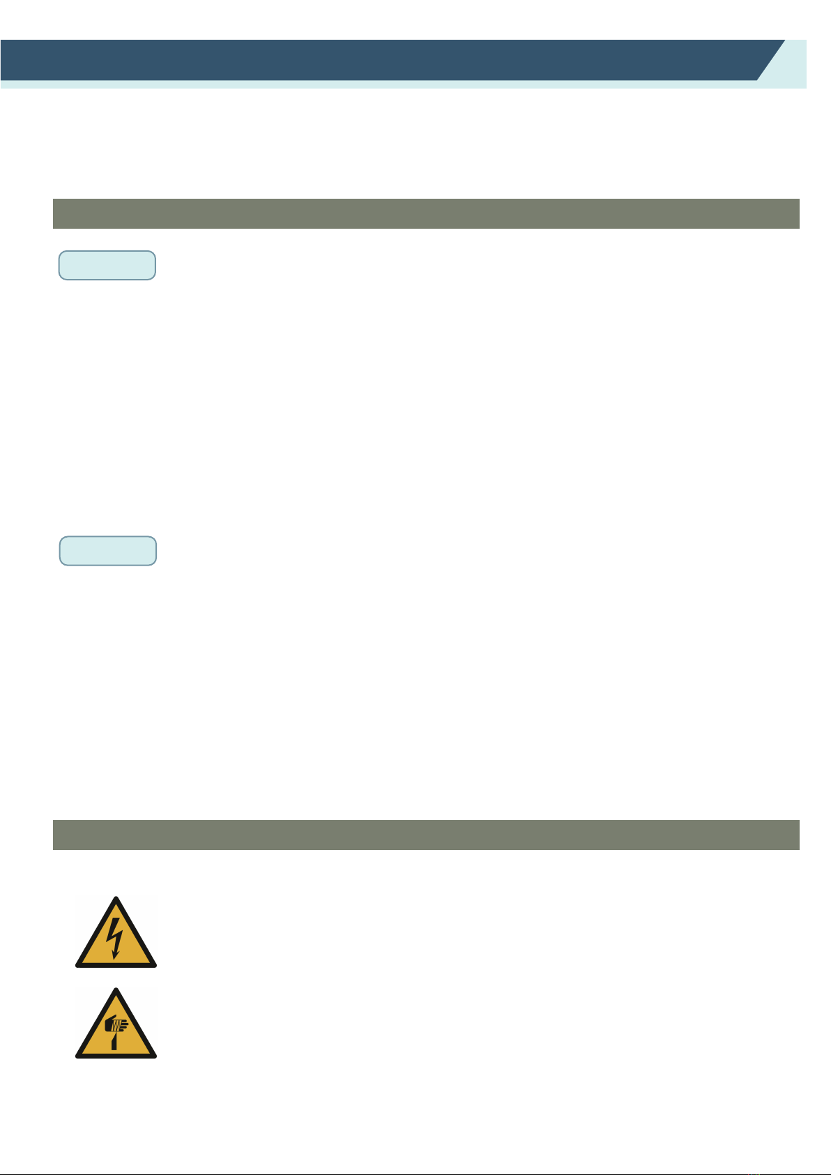
WARNING
Machine Caution Label
The following Warning Label is located on this cutting plotter. Please observe all the warning on the label
Thank you for choosing a VULCAN SC-350. To ensure high cutting quality and
optimal productivity, be sure to read this User's Manual thoroughly prior to use.
• No part of this publication may be reproduced, stored in a retrieval system, or transmitted, in any
form or by any means, without the prior written permission of VULCAN Corporation.
• The product specifications and other information in this manual are subject to change without notice.
• While every effort has been made to provide complete and accurate information, please contact your
sales representative or nearest VULCAN vendor if you find any unclear or erroneous information or
wish to make other comments or suggestions.
• Not with standing the stipulations in the preceding paragraph, VULCAN Corporation assumes no
liability for damages resulting from either the use of the information contained herein or the use of
the product.
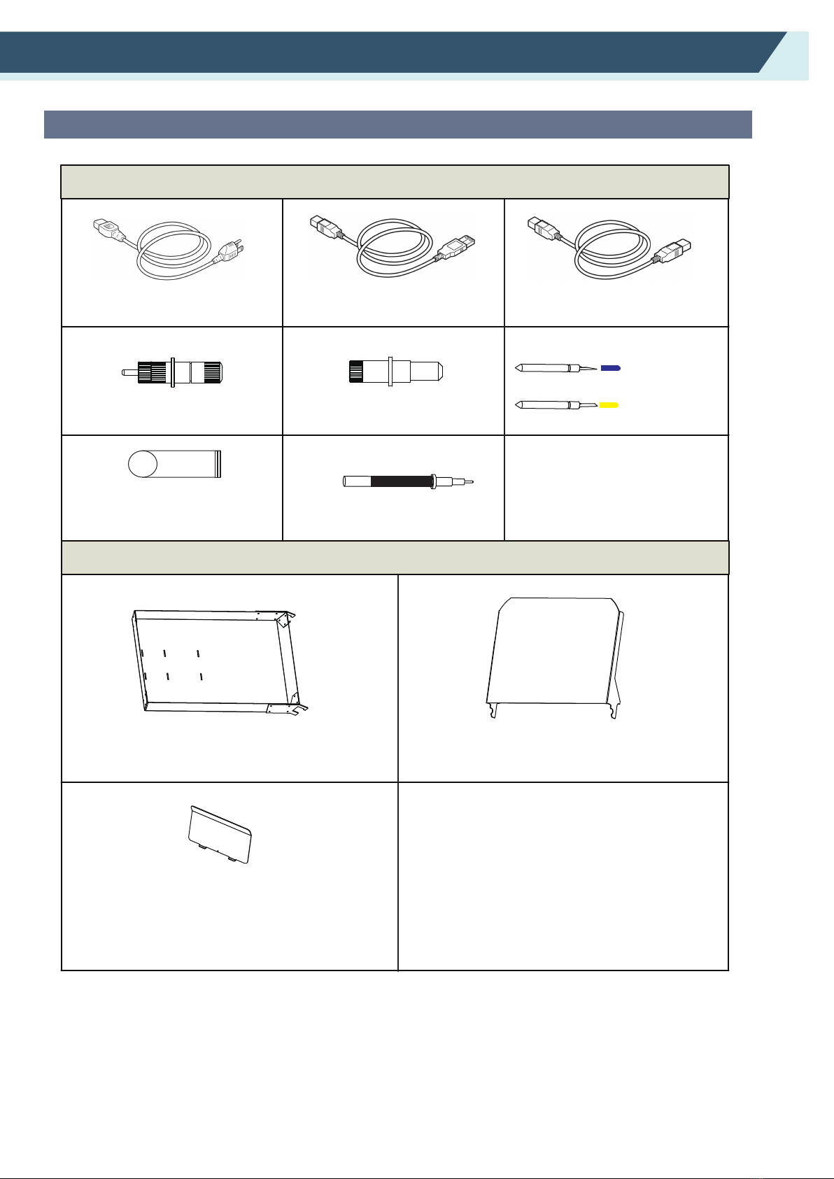
Manual
Cutter
Page 1
Warning; Electricity
Taking care to avoid coming into contact with electricity
Warning; Sharp element
Taking care to avoid injury from sharp elements (e.g. needles, blades)
Preface