• Samples should be aqueous. Measurements may be made in partially aqueous or some water-
miscible solvents. The results must be interpreted with caution as the full pH scale is shifted when
the solvent system changes.
• pH probes with an Ag/AgCl reference system and a single junction are not compatible with
solutions that contain silver complexing or binding agents such as TRIS, proteins and sulfides. To
measure in these solutions, use a double-junction pH probe, probe with an Ag+ (silver ion) barrier
or a Red Rod pH probe. Red Rod pH probes are compatible with these types of samples as they
have an encapsulated reference system.
• Proteins can collect on the sensing bulb. Make sure the probe stays clean when these types of
samples are measured.
• Do not use probes in solutions that are outside the temperature range of the probe.
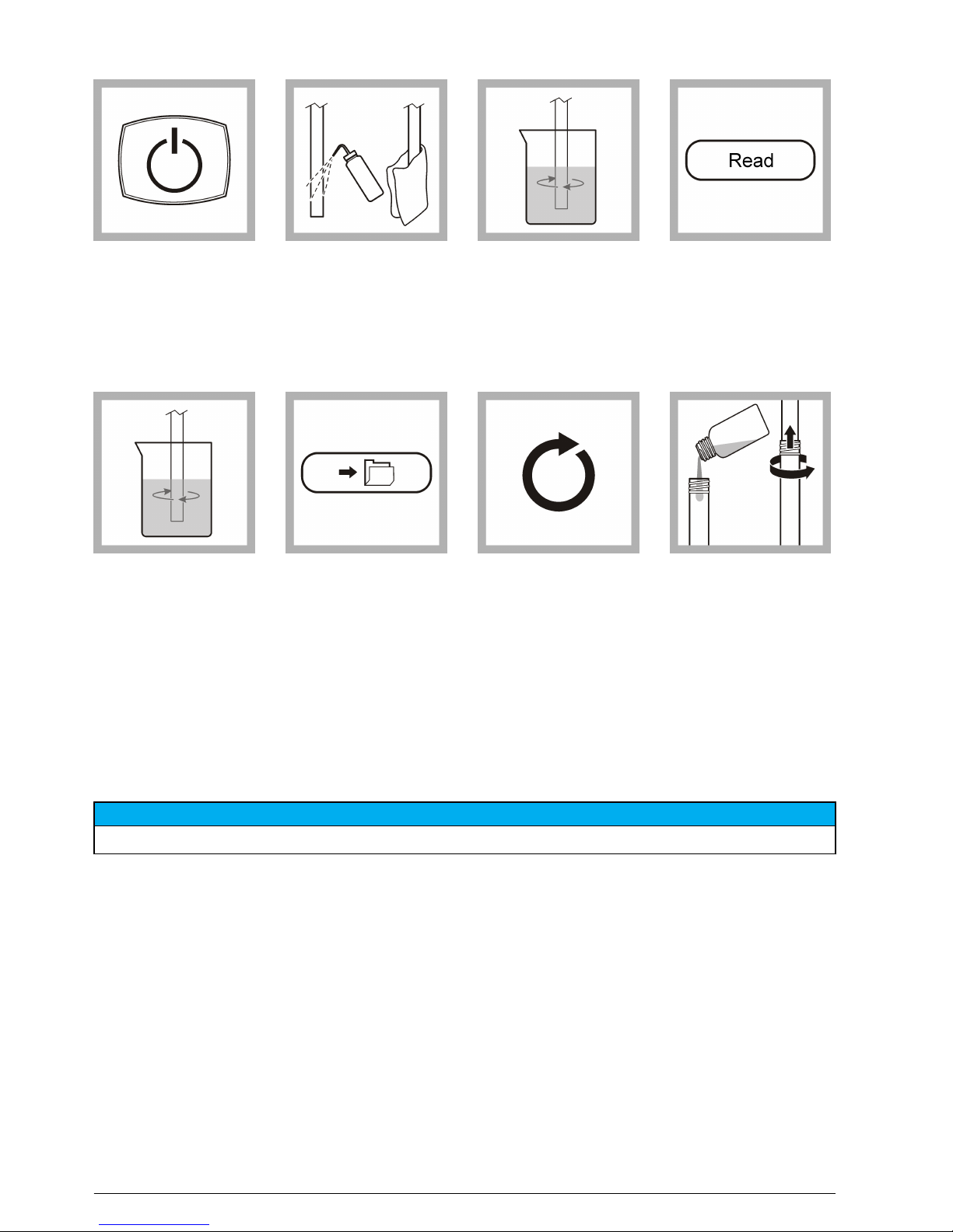
Sample measurement
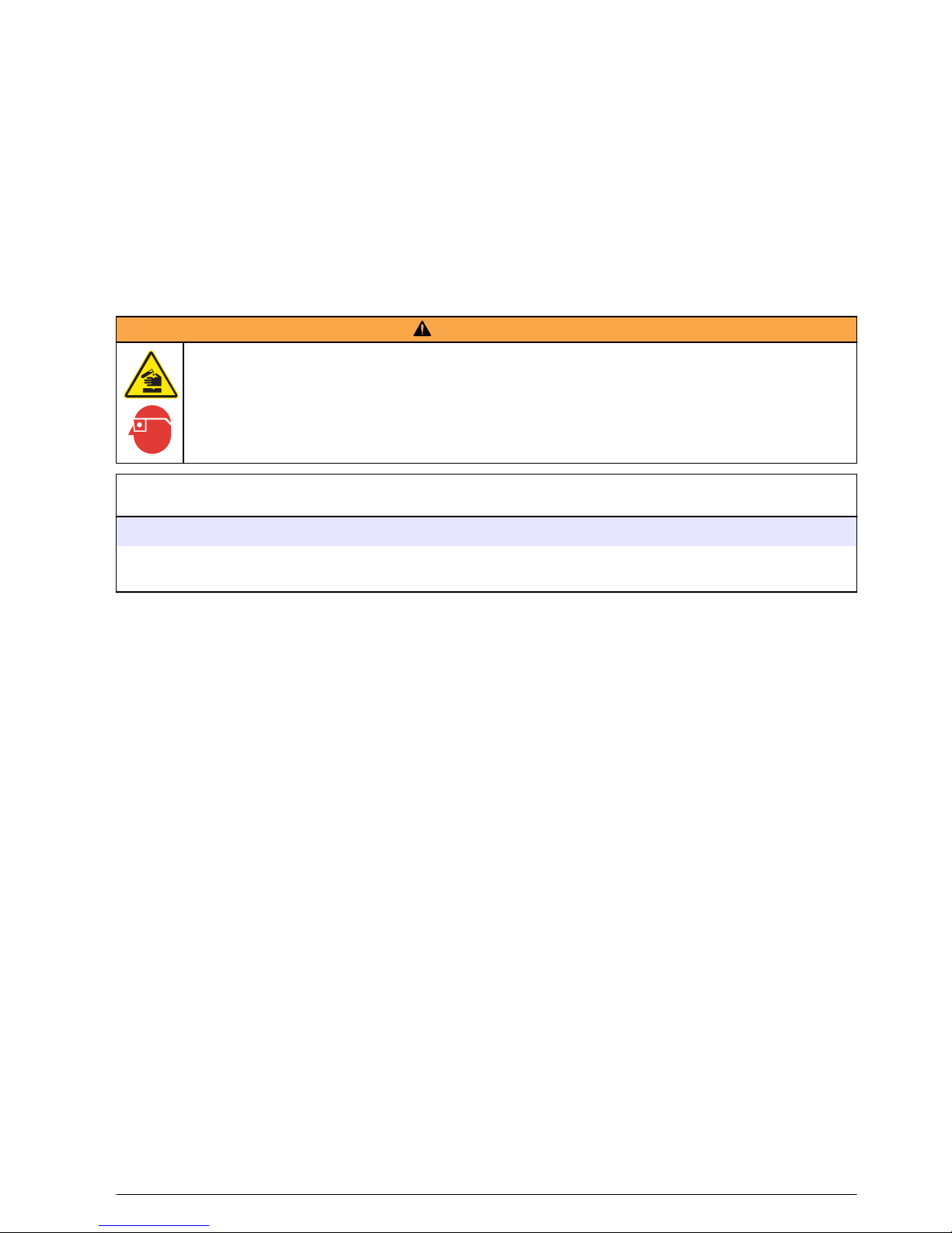
WARNING
Chemical exposure hazard. Obey laboratory safety procedures and wear all of the personal protective
equipment appropriate to the chemicals that are handled. Refer to the current material safety data
sheets (MSDS) for safety protocols.
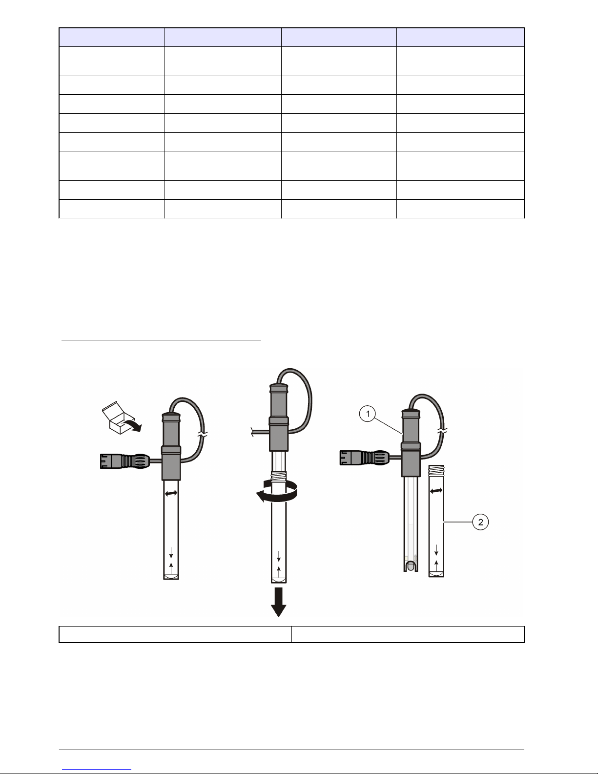
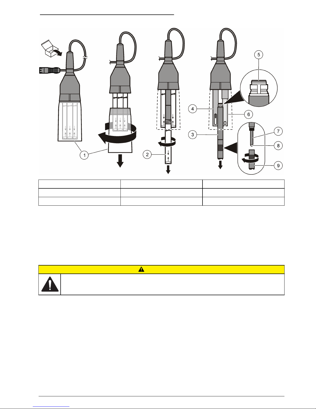
Before measurement:
Prepare the probe for use. Refer to Preparation for use on page 5.
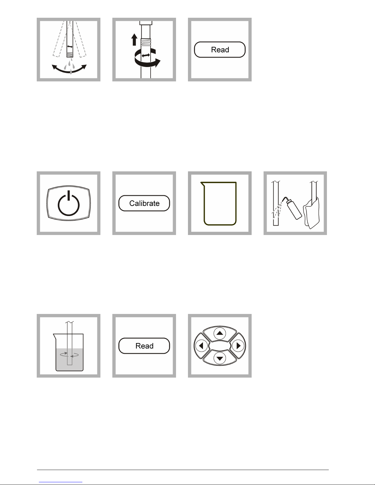
Calibrate the probe. Refer to Calibration on page 6. The manufacturer recommends that the probe is calibrated
at least once a day for the best measurement accuracy.
Measurement notes
• The calibration and sample measurement conditions must be as similar as possible (e.g., the
temperature of the solution, stir procedure, stir rate and position of the probe).
• Calibration of conductivity cells is important as the conductivity cell constant can change with time
and calibration identifies the actual cell constant versus the nominal value.
• Do not dilute conductivity standards or samples.
• When the probe is submerged, make sure that there are no air bubbles under the probe sensor
tip(s). Gently shake the probe from side to side to remove any air bubbles.
• Make sure that the reference junction is fully in the solution.
• If necessary, turn the protective shroud and remove it from the probe. The protective shroud
prevents damage to the sensors.
• Do not put the probe on the bottom or sides of the container.
• If stabilization is slow, shake the probe from side to side in the solution.
• Do not use probes in areas where EMF is present (i.e., voltaic cells, thermoelectric devices,
electrical generators, resistors and transformers). For use in process units (i.e., spot checking),
make sure that the meter is grounded.
• If a measurement error occurs, refer to Troubleshooting on page 12.
English 9