8
roCker/Waver oPeratIng InstrUCtIons
The VWR Rocker/Wavers are used for gentle mixing of laboratory samples. These
units have been designed for the speed/tilt and time functions to work independently
of one another. The speed/tilt can be re-set without re-setting the timer and the timer
can be stopped and started without interrupting the rocking/waving functions.
1. Getting ready:
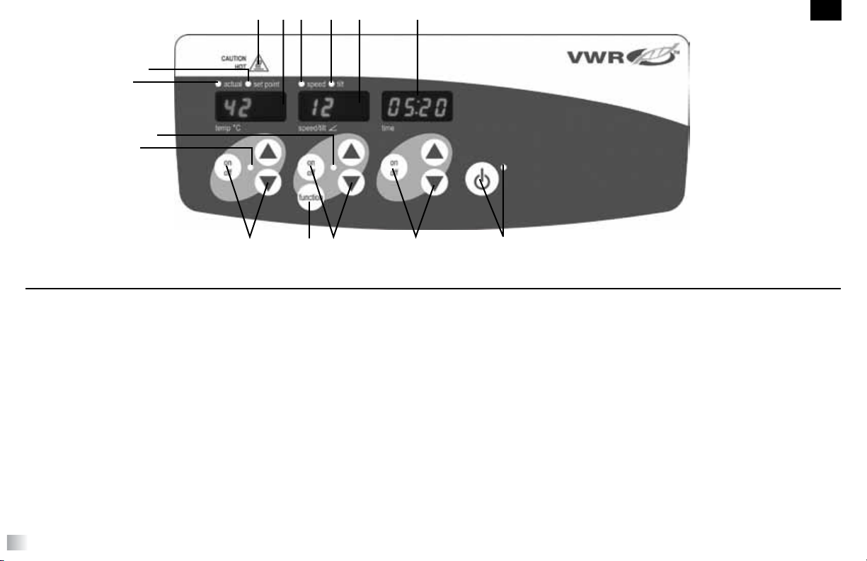
a. Plug the power cord into a properly grounded outlet. The standby indicator light will
illuminate, verifying power to the unit. Manually move the platform tray to a near
horizontal “home” position before powering unit.
b. Press the standby button to move the unit from standby mode. The standby
indicator light will shut off and the speed/tilt and time displays will illuminate and
display the previously used settings.
2. Setting tilt: Electronic tilt enables the user to adjust the angle of tray movement
while the unit is rocking/waving or while the unit is stopped.
a. Press the function button below the speed/tilt display until the tilt indicator light
illuminates. You are now ready to set the tilt angle.
b. Press the up/down arrows below the speed/tilt display until you reach the
desired angle. When you release the arrow button, the display will blink off and
then on indicating the new set angle has been accepted. The unit will complete
one rotation at the previously set angle, then smoothly change to the newly
programmed angle. The tilt indicator light will flash until the transition to the new
tilt angle is complete.
3. Setting speed:
a. Press the function button below the speed/tilt display until the speed indicator
light illuminates. You are now ready to set the speed.
b. Press the up/down arrows below the speed/tilt display until you reach the
desired speed. When you release the arrow button, the display will blink off and
then on indicating the new set speed has been accepted.
c. Press the on/off button to start the rocking/waving function. The indicator light below
the speed/tilt display will flash until the transition to the set speed is complete,
then the light will stay illuminated indicating the rocking/waving function is in
use.
d. To stop rocking/waving function, press the on/off button below the speed/tilt dis-
play. The unit will complete one full rotation then stop in the horizontal “home”
position. The speed indicator light will flash until the rotation is complete. When
the cycle is complete, the unit will automatically move to standby mode and the
standby indicator light will illuminate.
OPERATING TIPS
When the unit is running at slow speeds or high angles, making large changes to the
tilt angle or speed may take several minutes to complete. The quickest way to make
large changes to the speed or tilt angle is to stop the unit, change the speed or tilt angle,
then restart by pressing the on/off button below the speed/tilt display.
4. Setting time to zero (0:00) and continuous mode: Accumulated time.
a. Press and hold the on/off button below the time display. After three (3) seconds,
the display will indicate the previous set time.
b. Simultaneously press both the up and down arrows, the display will indicate
zero (0:00). The unit time is now set to zero (0:00) minutes. Alternately, you can
use the up/down arrows to get to zero (0:00).
c. Press the on/off button below the time display. The display will indicate the accu-
mulated time. The up/down arrows will become inactive. To stop timer, press
the on/off button again. IMPORTANT: This will NOT interrupt the rocking/wav-
ing function. Press the on/off button below the speed/tilt display to interrupt the
rocking/waving function.
d. To re-set, press and hold the on/off button below the time display. After three
(3) seconds, the display will indicate the previous set time, which was zero
(0:00).
EN