Bosch PFS 55 User manual

Robert Bosch GmbH
Power Tools Division
70745 Leinfelden-Echterdingen
Germany
www.bosch-pt.com
1 609 929 Y12 (2011.08) PS / 192 UNI
PFS 55
de Originalbetriebsanleitung
en Original instructions
fr Notice originale
es Manual original
pt Manual original
it Istruzioni originali
nl Oorspronkelijke
gebruiksaanwijzing
da Original brugsanvisning
sv Bruksanvisning i original
no Original driftsinstruks
fi Alkuperäiset ohjeet
el Ðñùôüôõðï ïäçãéþí ÷ñÞóçò
tr Orijinal işletme talimat
pl Instrukcja oryginalna
cs Původní návod k používání
sk Pôvodný návod na použitie
hu Eredeti használati utasítás
ru Îðèãèíàëüíîå ðóêîâîäñòâî ïî
ýêñïëóàòàöèè
uk Îðèã³íàëüíà ³íñòðóêö³ÿ ç
åêñïëóàòàö³¿
ro Instrucţiuni originale
bg Îðèãèíàëíà èíñòðóêöèÿ
sr Originalno uputstvo za rad
sl Izvirna navodila
hr Originalne upute za rad
et Algupärane kasutusjuhend
lv Instrukcijas oriģinālvalodā
lt Originali instrukcija
OBJ_BUCH-670-002.book Page 1 Monday, August 22, 2011 1:10 PM

| 3
Bosch Power Tools 1 609 929 Y12 | (22.8.11)
3
5
6
4
15
16
10
11
12
22
13 14
1
9
2
PFS 55
OBJ_BUCH-670-002.book Page 3 Monday, August 22, 2011 1:10 PM

1 609 929 Y12 | (22.8.11) Bosch Power Tools
4|
A1
B
A2
B1 B2
10
10
10
44
B
C1 C2
5-15 cm
OBJ_BUCH-670-002.book Page 4 Monday, August 22, 2011 1:10 PM

| 5
Bosch Power Tools 1 609 929 Y12 | (22.8.11)
D
F
G
E13
AB C
15
12
17
18
19
OBJ_BUCH-670-002.book Page 5 Monday, August 22, 2011 1:10 PM

1 609 929 Y12 | (22.8.11) Bosch Power Tools
6|
K
IH
21
8 3
7
8
2120
201314
11
10
+
800 ml600 ml
+
OBJ_BUCH-670-002.book Page 6 Monday, August 22, 2011 1:10 PM

14 | English
1 609 929 Y12 | (22.8.11) Bosch Power Tools
Luxemburg
Tel.: +32 2 588 0589
Fax: +32 2 588 0595
E-Mail: outillage.gereedschap@be.bosch.com
Entsorgung
Sprühpistole, Elektroeinheit, ZubehörundVerpackungensol-
len einer umweltgerechten Wiederverwertung zugeführt wer-
den.
Werfen Sie Elektrowerkzeuge nicht in den Hausmüll!
Nur für EU-Länder:
Gemäß der Europäischen Richtlinie
2002/96/EG über Elektro- und Elektronik-
AltgeräteundihrerUmsetzunginnationales
Recht müssen nicht mehr gebrauchsfähige
Elektrowerkzeuge getrennt gesammelt und
einer umweltgerechten Wiederverwertung
zugeführt werden.
Änderungen vorbehalten.
English
Safety Notes
General Power Tool Safety Warnings
Read all safety warnings, instructions
including Material Safety Data Sheets
(MSDS), and container labels provided with the paints
and solvents. Failure to follow the warnings and instructions
may result in electric shock, fire and/or serious injury.
Save all warningsand instructions for future reference.
The term “power tool” in the warnings refers to your mains-
operated (corded) power tool or battery-operated (cordless)
power tool.
Workplace safety
fKeep work area clean and well lit. Cluttered and dark ar-
eas invite accidents.
fKeep children and bystanders away while operating a
power tool. Distractions can cause you to loose control.
Electrical safety
fPower tool plugs must match the outlet. Never modify
the plug in any way. Do not use any adapter plugs with
earthed (grounded) power tools. Unmodified plugs and
matching outlets will reduce risk of electric shock.
fAvoidbodycontactwithearthedorgroundedsurfaces,
such as pipes, radiators, ranges and refrigerators.
There is an increased risk of electric shock if your body is
earthed or grounded.
fDo not expose power tools to rain or wet conditions.
Waterenteringapowertoolwillincreasetheriskofelectric
shock.
fDo not abuse the cord. Never use the cord for carrying,
pulling or unplugging the power tool. Keep cord away
from heat, oil, sharp edges and moving parts. Damaged
or entangled cords increase the risk of electric shock.
fWhen operating a power tool outdoors, use an exten-
sion cord suitable for outdoor use. Use of a cord suitable
for outdoor use reduces the risk of electric shock.
fIf operating a power tool in a damp location is unavoid-
able, use a residual current device (RCD) protected
supply. Use of anRCD reduces the risk of electric shock.
Personal safety
fStay alert, watch what you are doing and use common
sense when operating a power tool. Do not use a power
tool while you are tired or underthe influence of drugs,
alcohol or medication. A moment of inattention while op-
erating power tools may result in serious personal injury.
fUse safety equipment. Always wear eye protection.
Safety equipment such as dusk mask, non-skid safety
shoes, hard hat, or hearing protection used for appropri-
ate conditions will reduce personal injuries.
fPrevent unintentional starting. Ensure the switch is in
the off-position before connecting to power source
and/or battery pack, picking up or carrying the tool.
Carrying power tools with your finger on the switch or en-
ergising power tools that have the switch on invites acci-
dents.
fDo not overreach. Keep proper footing and balance at
all times. This enables better control of the power tool in
unexpected situations.
fDress properly. Do not wear loose clothing or jewel-
lery. Keep your hair, clothing and gloves away from
moving parts. Loose clothes, jewellery or long hair can be
caught in moving parts.
Use and care of the power tool
fDo not force the power tool.Use the correct power tool
for your application. The correct power tool will do the
job better and safer at the rate for which it was designed.
fDo not use the power tool if the switch does not turn it
on and off. Any power tool that cannot be controlled with
the switch is dangerous and must be repaired.
fDisconnect the plug from the power source and/or the
battery pack from the power tool before making any
adjustments, changing accessories, or storing power
tools. Such preventive safety measures reduce the risk of
starting the power tool accidentally.
fStore idle power tools out of the reach of children and
do not allow persons unfamiliar with the power tool or
these instructions to operate the power tool. Power
tools are dangerous in the hands of untrained users.
fMaintain power tools. Check for misalignment or bind-
ing of moving parts, breakage of parts and any other
condition that may affect the power tool’s operation. If
damaged, have the power tool repaired before use.
Many accidents are caused by poorly maintained power
tools.
fUse the power tool, accessories and application tools
etc. in accordance with these instructions, taking into
account the working conditions and the work to be per-
WARNING
OBJ_BUCH-670-002.book Page 14 Monday, August 22, 2011 1:10 PM

English | 15
Bosch Power Tools 1 609 929 Y12 | (22.8.11)
formed. Use of power tools for operations different from
those intended could result in a hazardous situation.
Service
fHave yourpowertoolserviced by a qualified repair per-
son using only identical replacement parts. This will en-
sure that the safety of the power tool is maintained.
Safety Warnings for Fine-spray Systems
fKeep area clean well lit and free of paint or solvent con-
tainers, rags, and other flammable materials. Sponta-
neous combustion may occur. Fire extinguisher equip-
ment shall be present and working at all times.
fProvide for good ventilation in the spraying area and
for sufficient fresh air in the complete room. Evaporat-
ing inflammable solvents create an explosive environment.
fDo not use materials with a flashpoint below 21 °C for
spraying and cleaning. Use water-based materials,
non-volatile hydrocarbons or similar materials. Fast
evaporating solvents create an explosive environment.
fDonotsprayinthevicinintyofignitionsources,suchas
static electricity sparks, open flames, pilot lights, hot
objects, engines/motors, cigarettes and sparks from
plugging in or unplugging power cords or operating
switches. Such spark sources can ignite the spraying vi-
cinity/environment.
fDo not spray any liquid of unknown hazard potential.
Unknown materials can create hazardous conditions.
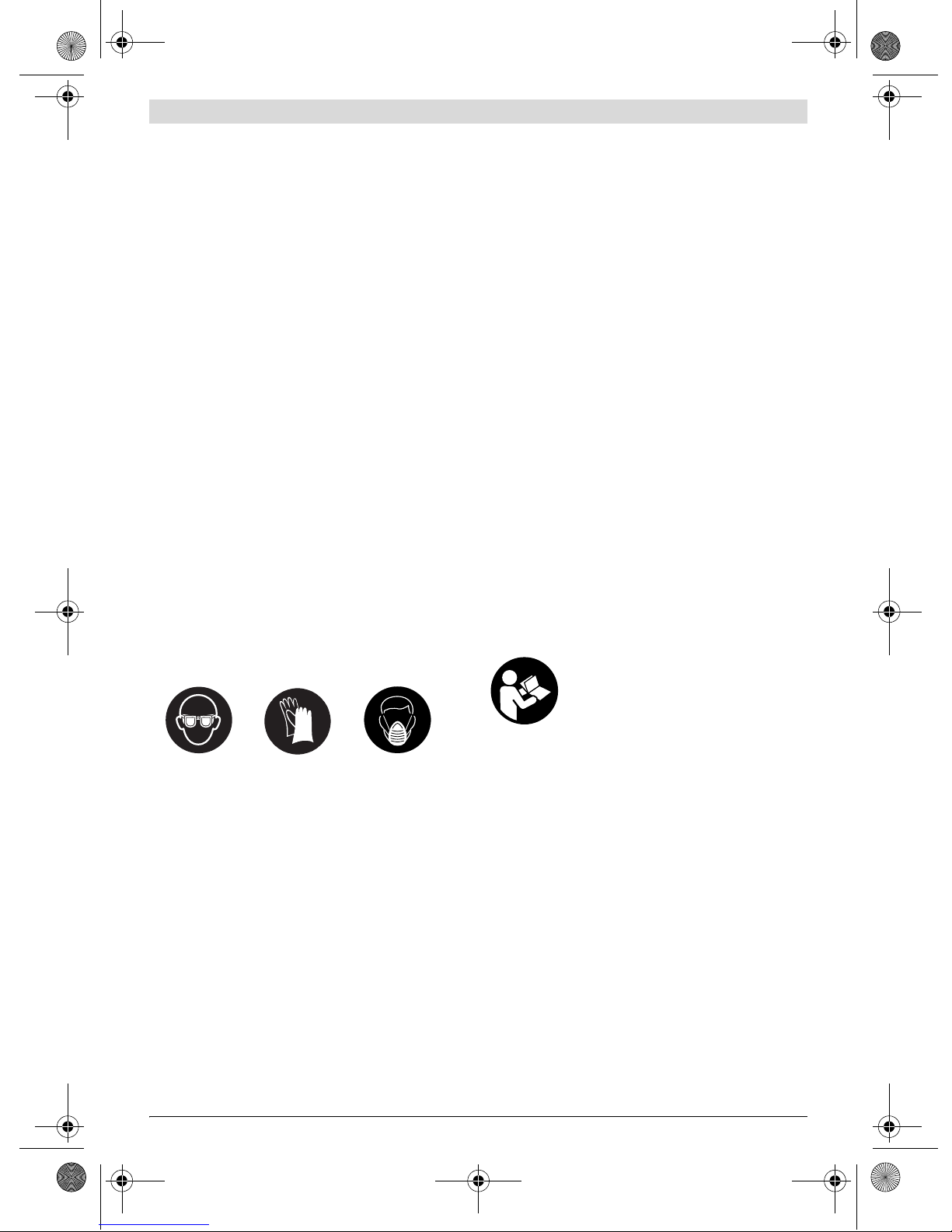
fWear additional protective equipment such as appro-
priate protective glovesand protective masks or respi-
rators when spraying or handling chemicals. Wearing
protective equipment for the appropriate conditions re-
duces the exposure to hazardous substances.
fNever point the spray jet against yourself, towards oth-
er persons or animals. Keep your hands and other body
parts away from the spray jet. If the spray jet should
penetrate the skin, seek medical attention immediate-
ly from a doctor. The material being sprayed can even
penetrate the skin through a glove and be injected into
your body.
fDonottreat aninjectionasa simplecut.Ahigh-pressure
spray is able to inject toxins into the body andcause seri-
ousbodilyinjury.Intheeventthataninjectionoccurs,seek
medical attention immediately.
fBe aware of possible hazards from the spray material.
Observe the information on drums/tanks/tins as well
as manufacturer information of the spray material, in-
cluding the request to wear personal protective equip-
ment. The manufacturer's instructions are to be observed
in order to reduce the risk of fire as well as injuries caused
through toxins, carcinogens, etc.
fUse only nozzles/nozzle inserts specified by the manu-
facturer. Never spray without the nozzle protection
mounted. Use of a special nozzle insert with the corre-
sponding nozzle protection reduces the probability that a
high-pressure jet penetrates the skin and injects toxins in-
to the body.
fExercisecautionwhencleaningandchanging nozzle in-
serts. If the nozzle insert should become clogged dur-
ing spraying, follow the manufacturer's instructions
for switching off the system and relieving the pressure
before removing the nozzle. Fluids under high pressure
can penetrate the skin, inject toxins into the body and lead
to serious injury.
fKeep the plug of the mains cord and the trigger switch
of the spray gun clear of paint and other fluids. Never
hold the cord by its connectors to support it. Failure to
follow the instruction can lead to electric shock.
Products sold in GB only: Your product is fitted with an
BS 1363/A approved electric plug with internal fuse (ASTA
approved to BS 1362).
If the plug is not suitable for your socket outlets, it should be
cut off and an appropriate plug fitted in its place by an author-
ised customer service agent. The replacement plug should
have the same fuse rating as the original plug.
The severed plug must be disposed of to avoid a possible
shock hazard and should never be inserted into a mains sock-
et elsewhere.
Productssold in AUSand NZonly: Use a residual current de-
vice (RCD) with a rated residual current of 30 mA or less.
Product Description and
Specifications
Read all safety warnings and all instruc-
tions. Failure to follow the warnings and in-
structions may result in electric shock, fire
and/or serious injury.
Intended Use
The power tool is intended for atomising solvent-based and
water-dilutable paints, finishes, primers, clear finishes, auto-
motive finishes, staining sealers, wood sealer-preservatives,
plant protectives, oil and disinfection agents.
The power tool is not suitable for spraying dispersions and la-
tex paint, caustic solutions, acidic coating materials, coating
materials with granules or solids as well as spray and drip-im-
peding materials.
Product Features
The numbering of the components shown refers to the repre-
sentation of the power tool on the graphic pages.
1 Electrical unit
2Cable clamp
3Air filter cover
4SDS release button
5Mains cable
6Handle extension (only for 800 ml container)
7Screw for air-filter cover
OBJ_BUCH-670-002.book Page 15 Monday, August 22, 2011 1:10 PM

16 | English
1 609 929 Y12 | (22.8.11) Bosch Power Tools
8Air filter
9Spraygun
10 Suction tube with container seal
11 Container for spray material, 600 ml
Container for spray material, 800 ml*
12 Vent cover
13 Air cap
14 Union nut
15 Thumbwheel for spraying capacity
16 Trigger switch
17 Venting hose
18 Venting valve
19 Membrane
20 Nozzle
21 Nozzle seal
22 Measuring cup
*Accessories shown or described are not part of the standard de-
livery scope of the product. A complete overview of accessories
can be found in our accessories program.
Technical Data
Noise/Vibration Information
Measured sound values determined according to EN 60745.
Typically the A-weighted sound pressure level of the product
is 74 dB(A). Uncertainty K=3 dB.
The noise level when working can exceed 80 dB(A).
Wear hearing protection!
Vibration total values ah(triax vector sum) and uncertainty K
determined according to EN 60745:
ah<2.5m/s2, K= 1.5 m/s2.
The vibration emission level given in this information sheet
has been measured in accordance with a standardised test
given in EN 60745 and may be used to compare one tool with
another. It may be used for a preliminary assessment of expo-
sure.
The declared vibration emission level represents the main ap-
plications of the tool. However if the tool is used for different
applications,withdifferentaccessoriesorpoorlymaintained,
the vibration emission may differ. This may significantly in-
crease the exposure level over the total working period.
An estimation of thelevel of exposure to vibration should also
take into account the times when the tool is switched off or
when it is running but not actually doing the job. This may sig-
nificantly reduce the exposure level over the total working pe-
riod.
Identify additional safety measures to protect the operator
fromthe effectsofvibration suchas:maintain thetooland the
accessories, keep hands warm, organise work patterns.
Declaration of Conformity
We declare under our sole responsibility that the product de-
scribed under “Technical Data” is in conformity with the fol-
lowing standards or standardization documents: EN 60745
according to the provisions of the directives 2011/65/EU,
2004/108/EC, 2006/42/EC.
Technical file (2006/42/EC) at:
Robert Bosch GmbH, Dept. PT/ESC,
D-70745 Leinfelden-Echterdingen
Robert Bosch GmbH, Power Tools Division
D-70745 Leinfelden-Echterdingen
Leinfelden, 22.08.2011
Assembly
fBefore any work on the machine itself, pull the mains
plug.
Mounting the Spray Gun and the Electrical Unit
(see figures A1–A2)
Connecting the Electrical Unit with the Spray Gun
– Insert the spray gun 9onto the electrical unit 1until it can
be heard to engage.
Removing the Electrical Unit
– Press and hold the two red SDS release buttons 4and pull
the spray gun 9out of the electrical unit.
Operation
Preparing for Operation
fSpraying on the sides of water bodies (lakes, rivers,
etc.) or neighbouring surfaces in the direct catchment
area is not permitted.
When purchasing paint, varnish and spray material, pay at-
tention to their environmental compatibility.
Preparing the Spray Surface
Note: Cover off the vicinity of the spray surface thoroughly
and generously.
Fine-spray System PFS 55
Article number 3 603 B06 0..
Rated power input W 280
Spraying capacity g/min 0–110
Atomising output W55
Required time for application
of paint on 5 m2min 12
Container capacity for spray
material ml 600
Weight according to
EPTA-Procedure 01/2003 kg 1.3
Protection class /II
The values given are valid for a nominal voltage [U] of 230 V. For differ-
ent voltages and models for specific countries, these values can vary.
Please observe the article number on the type plate of your machine.
The trade names of the individual machines may vary.
Dr. Egbert Schneider
Senior Vice President
Engineering
Dr. Eckerhard Strötgen
Head of Product
Certification
OBJ_BUCH-670-002.book Page 16 Monday, August 22, 2011 1:10 PM

English | 17
Bosch Power Tools 1 609 929 Y12 | (22.8.11)
The spray mist contaminates the environment. When spray-
ing in enclosures, surfaces not covered can become contami-
nated.
The spray surface must be clean, dry and grease-free.
– Roughen smooth surfaces and then remove the sanding
dust.
Suitable spray materials and recommended diluting
agents
fWhen diluting, pay attention that the spray material
and the diluting agent correspond. When using a faulty
diluting agent, lumps can develop that can lead to clogging
of the spray gun.
The tool is not suitable for processing dispersion paint (wall
paint/latex).
Please also observe the practical advice/tips of the spray ma-
terial manufacturers.
Diluting Spray Material
For spray material that needs to be diluted, proceed as fol-
lows:
– Take the measuring cup 22.
– Stir the spray material thoroughly.
– Fill a sufficient quantity of spray material into the spray-
material container 11. (see “Filling in Spray Material”,
page 17)
– Dilute the spray material by 10 % with paint thinner. Ex-
amples:
– Stir the spray material thoroughly.
– Carry out a test-spray run on a test surface. (see “Spray-
ing”, page 17)
When the spraying pattern is perfect, start the spray job.
or
When the spraying result is not satisfactory or when no paint
comesout, pleasecontinue asdescribedunder“Correctionof
Malfunctions” on page 19.
Filling in Spray Material (see figures B1–B2)
fBefore any work on the machine itself, pull the mains
plug.
– Unscrew the container 11 from the spray gun.
– Turn the suction tube 10 so that the spray material can be
sprayed with almost no residue:
– Fillthespray material into thecontainerandscrewthecon-
tainer firmly to the spray gun.
Starting Operation
fObserve correct mains voltage! The voltage of the pow-
er source must agree with the voltage specified on the
nameplate of the machine. Power tools marked with
230 V can also be operated with 220 V.
fPay attention that the power tool cannot draw in dust
or other contamination during operation.
Switching On
– Plug the mains plug into a socket outlet.
– Grasp the power tool and point it at the spray surface.
The power tool is equipped with a two-step trigger switch 16.
The first step starts the turbine. The second step transports
the spraying material.
– Pull the trigger switch 16 until spraying material starts to
come out.
Switching Off
– Release the trigger switch 16.
– Pull the mains plug from the socket outlet.
Working Advice
Spraying (see figures C–D)
Note: Observe the wind direction when operating the power
tool outdoors.
– Firstly, carry out a test-spray run and adjust the spray pat-
tern and the spray material quantityaccording to thespray
material. (For adjustments, see the following sections)
– Makesureto hold thespraygun vertical tothespray object
at a uniform clearance between 5 – 15 cm.
– Begin the spraying procedure outside the target area.
– Move the spray gun evenly cross-wise or up-and-down, de-
pending on the spray pattern setting.
Anevensurface qualityisachieved when the pathsoverlap
by4–5cm.
– Avoid interruptions within the spray surface.
Guiding the spray gun evenly will provide uniform surface
quality.
Non-uniform clearance and spray angle lead to heavy forma-
tion of paint mist and thus to an uneven surface.
– End the spraying procedure outside the target area.
Never spray the container completely empty. When the suc-
tion tube no longer immerses in the spray material, the spray
jet will break off, resulting in a non-uniform surface.
When coating material builds up on the nozzle and air cap,
clean both parts with the corresponding solvent.
Note:Only place down the power tool on a level and clean sur-
face so that it can not tip over.
Spray material Recommended
dilution
Wood preservatives, mordants/strip-
pers, oils, varnishes, impregnations,
rust-protection primers
undiluted
Disinfectants, plant protectants, water,
wallpaper stripper
undiluted
Solvent or water-dilutable paints,
primers, radiator paint, automotive top
coats, thick-coat finishes
At least 10 %
diluted
Amount of spray material [ml] 200 300 400 500
Paint thinner [ml] 20 30 40 50
For spray jobs on horizontal
surfaces/objects
toward the front in nozzle
direction
For spray jobs overhead toward the rear in handle
direction
OBJ_BUCH-670-002.book Page 17 Monday, August 22, 2011 1:10 PM

18 | English
1 609 929 Y12 | (22.8.11) Bosch Power Tools
Adjusting the Spray Pattern (see figure E)
fNeveractuate the triggerswitch16 while adjustingthe
air cap 13.
– Loosen the union nut 14.
– Turn the air cap 13 to the requested position.
– Firmly retighten the union nut.
Adjusting the Spraying Capacity (see figure F)
– To adjust the requested spraying capacity, turn the thum-
bwheel 15:
–: Min. spraying capacity,
+: Max. spraying capacity.
Maintenance and Service
Maintenance and Cleaning
fBefore any work on the machine itself, pull the mains
plug.
fNeverimmerse theelectricalunitinto solventor water.
Clean the housing using only a moist cloth.
Cleaning (see figures H–I)
Proper cleaning is the requirement for flawless operation of
the spray gun. Improper or lack of cleaning voids warranty
claims.
Always clean the spray gun and the container with the respec-
tive diluting agent (paint thinner or water) for the spray mate-
rial being used.
Never clean the nozzle and air holes of the spray gun with
pointed metal objects.
Donotpour diluted spraymaterial back intotheoriginalspray
material drum/tin for storage.
Clean the spray gun thoroughly after having sprayed material
hazardous to one's health.
– Unplugthemains plugandpullthetriggerswitch16 sothat
the spraying material can flow back into the container.
– Remove the electrical unit. (see page 16)
– Unscrew the container 11 and empty the remaining spray
material.
– Fill diluting agent (paint thinner or water) into the contain-
er and screw it to the spray gun.
– Shake the spray gun several times.
– Connect the spray gun to the electrical unit again. (see
page 16)
– Plug the mains plug into a socket outlet, pull the trigger
switch and spray the diluting agent into an empty material
tin.
– Repeat the process until clear diluting agent emerges from
the spray gun.
– Unplug the mains plug and remove the electrical unit.
– Completely empty thecontainer 11.
– Check if the suction tube with the container seal 10 is free
of spray material and undamaged.
– Clean the outside of the container and the spray gun with a
cloth moistened in paint thinner.
– Unscrew the union nut 14 and the air cap 13.
– Clean the nozzle 20 and the nozzle needle with diluting
agent.
From time to time, the nozzle seal 21 must also be cleaned.
– Remove the nozzle 20 and the nozzle seal 21.
If required, use a pointed object, as the nozzle seal is seat-
ed firmly to the spray gun.
– Clean the nozzle seal with diluting agent.
– Reinstallthenozzlesealinthespray gun.Pay attentionthat
the groove points away from the spray gun.
– Mount the nozzle onto the spray gun body and turn itto the
correct position.
– Mount the air cap 13 onto the nozzle and tighten with the
union nut 14.
Cleaning the Venting Hose (see figure G)
When the venting hose 17 is contaminated with spraying ma-
terial, it must be cleaned.
– Remove the vent cover 12.
– Pull off the venting hose 17.
– Unscrew the venting valve 18.
– Remove the membrane 19.
–Clean the venting hose, the venting valve and the mem-
brane with an appropriate paint thinner.
– After cleaning, reinsert the membrane again first. Pay at-
tention that the longer rod faces upward.
– Screw the venting valve on again.
– Afterwards, attach the venting hose to the valve first,then
at the top on the spray gun.
– Reattach the vent cover again.
Air cap Jet Application
A
Vertical flat jet for horizontal
working direction
B
Horizontal flat jet for vertical
working direction
C
Round jet for corners, edges and
hard to reach locations
Spraying capacity Adjustment
Toomuch materialontargetarea: The spraying capacity
must be reduced.
– Turn the thumbwheel
15 in direction –.
Not enough material on target ar-
ea:
The spraying capacity
must be increased.
– Turn the thumbwheel
15 in direction +.
OBJ_BUCH-670-002.book Page 18 Monday, August 22, 2011 1:10 PM

English | 19
Bosch Power Tools 1 609 929 Y12 | (22.8.11)
Changing the Air Filter (see figure L)
Note: Never operate the powr tool without the air filter. With-
out the air filter, dirt/contamination can be drawn in and can
influence the operation of the power tool.
The air filter must be replaced when soiled.
– Loosen screw 7.
– Remove the air filter cover 3.
– Replace the air filter.
– Reattach the air filter cover and screw in the screw again.
Material Disposal
Diluting agent and remainders of spray material must be dis-
posed of in an environmentally-friendly manner. Observe the
manufacturer’sdisposalinformationand the local regulations
for disposal of hazardous waste.
Chemicals harmful to the environment may not be disposed
of into soil, groundwater or bodies of water. Never pour
chemicals harmful to the environment into the sewerage sys-
tem!
Correction of Malfunctions
Maintenance
If the machine should fail despite the care taken in manufac-
turingand testing procedures,repair shouldbecarried out by
an after-sales service centre for Bosch power tools.
In all correspondence and spare parts order,pleasealways in-
clude the 10-digit article number given on the type plate of
the machine.
Problem Cause Corrective Measure
Spray material does not cover
properly Spraying capacity too low Turn thumbwheel 15 in direction +
Clearance to target area too large Reduce spray distance
Not enough spray material on target area,
too few spray paths sprayed over target area
Apply more spray paths over target area
Spray material too viscous Thin down the spray material by 10% again
and carry out a test-spray run
Spray material runs off after
coating
Too much spray material applied Turn thumbwheel 15 in direction –
Clearance to target area too close Increase spray distance
Viscosity of spray material too low Add original spray material
Spray material applied too often over same
spot
Remove spray material; reduce number of
spray paths over same spot
Atomisation too course Spraying capacity too high Turn thumbwheel 15 in direction –
Nozzle 20 soiled Clean nozzle
Too little pressure build-up incontainer 11 Screw container firmly against spray gun
Spray material too viscous Thin down the spray material by 10% again
and carry out a test-spray run
Air filter heavily soiled Changing the Air Filter
Excessive paint mist Too much spray material applied Turn thumbwheel 15 in direction –
Clearance to spray surface too large Reduce spray distance
Spray jet pulsates Not enough spray material in container Refill spray material
Venting hole on suction tube 10 clogged Clean suction tube and hole
Air filter heavily soiled Changing the Air Filter
Spray material too viscous Thin down the spray material by 10% again
and carry out a test-spray run
Spray material drips from the
nozzle
Build-up of spray material on nozzle 20 and
air cap 13 Clean nozzle and air cap
Nozzle 20 worn Replace nozzle
Nozzle 20 loose Tighten union nut 14
No spray material emerges from
the nozzle
Nozzle 20 clogged Clean nozzle
Suction tube 10 clogged Clean suction tube
Venting hole on suction tube 10 clogged Clean suction tube and hole
Suction tube 10 loose Insert suction tube properly
No pressure build-up in container 11 Screw container firmly against spray gun
Spray material too viscous Thin down the spray material by 10% again
and carry out a test-spray run
OBJ_BUCH-670-002.book Page 19 Monday, August 22, 2011 1:10 PM
Other manuals for PFS 55
6
Table of contents
Other Bosch Paint Sprayer manuals

Bosch
Bosch PFS 3000-2 User manual

Bosch
Bosch PFS 1000 User manual

Bosch
Bosch PFS 5000E User manual

Bosch
Bosch PFS 1000 User manual

Bosch
Bosch 0603206200 User manual

Bosch
Bosch PFS 5000E User manual

Bosch
Bosch PFS 55 User manual

Bosch
Bosch PFS 3000-2 User manual

Bosch
Bosch PFS 105 User manual

Bosch
Bosch PFS 55 User manual

Bosch
Bosch 2 608 190 048 User manual

Bosch
Bosch 0603207200 User manual

Bosch
Bosch PFS 1000 User manual

Bosch
Bosch PFS 105 E User manual

Bosch
Bosch PFS 5000 E User manual

Bosch
Bosch PFS 55 User manual

Bosch
Bosch PFS 7000 User manual

Bosch
Bosch PFS 55 User manual

Bosch
Bosch PFS 65 User manual

Bosch
Bosch PFS 3000-2 User manual