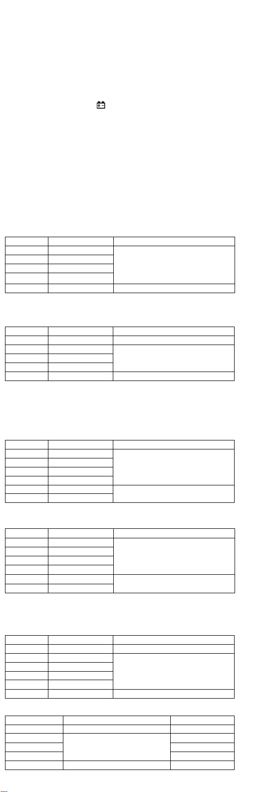
6-7 Frequency
Range Accuracy Resolution
5.12Hz
± (0.1% of rdg + 5 digits)
0.001Hz
51.2Hz 0.01Hz
512Hz 0.1Hz
5.12kHz 1Hz
51.2kHz 10Hz
512kHz 100Hz
5.12MHz 1kHz
-- Sensitivity: sine wave 0.6V rms (5.12MHz: 1.5V rms)
-- Overload protection: 250V DC or AC rms
6-8 Duty cycle
0.1%~99.9%: ± ( 2.0% of rdg + 2 digits ), Frequency lower than 10kHz
-- Sensitivity: sine wave 0.6V rms
-- Overload protection: 250V DC or AC rms
6-9 Temperature
Range Accuracy Resolution
℃-20~150℃± ( 3℃+ 1digit ) 1℃
150~1000℃± ( 3% of rdg + 2digits )
-- NiCr-NiSi sensor
-- Overload protection: 400mA/250V PPTC Resettable Fuse
6-10 Battery test
Range Accuracy Test Condition
±(5.0% of rdg + 5 digits) Loading Current:
Approx. 25mA
-- Battery voltage range: 1.5V~12V
-- Overload protection: 400mA/250V PPTC Resettable Fuse
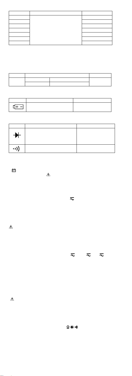
6-11 Diode and Audible continuity test
Range Description Test Condition
Display read approximately
forward voltage of diode
Forward DC current
approx. 0.4mA
Reversed DC voltage
approx. 1.5V
Built-in buzzer sounds if
resistance is less than 100Ω
Open circuit voltage
approx. 0.5V
Overload protection: 250V DC or AC rms
7. OPERATING INSTRUCTIONS
7-1 Attention before operation
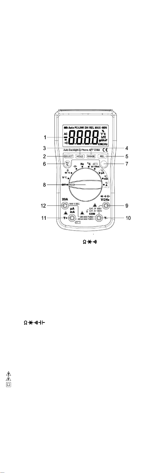
7-1-1 Check battery. When the battery voltage drop below proper operation range,
the “ ” symbol will appear on the LCD display and the battery need to changed.
7-1-2 Pay attention to the “ ” besides the input jack which shows that the input
voltage or current should be within the specified value.
7-1-3 The range switch should be positioned to desired range for measurement
before operation.
7-2 Measuring DC & AC Voltage
7-2-1 Connect the black test lead to COM jack and the red to VΩHz jack.
7-2-2 Set the rotary switch at the desired “V”range position, it shows symbol for
testing DC voltage, if you want to test AC voltage, push “SELECT” button switch,
then if you want to test AC 400mV, push “RANGE”to choose.
7-2-3 Connect test leads across the source or load under measurement.
7-2-4 You can get reading from LCD. The polarity of the red lead connection will be
indicated along with the DC voltage value.
NOTE:
1.“” means you can’t input the voltage more than 1000V, it’s possible to show
higher voltage, but it may destroy the inner circuit or pose a shock.
2.Be cautious against shock when measuring high Voltage.
7-3 Measuring DC & AC Current
7-3-1 Connect the black test lead to COM jack and the red to the μAmA jack for a
maximum 400mA current , for a maximum 2A or 20A current, move the red lead to
the 20A jack.
7-3-2 Set the rotary switch at the desired “uA ”& “mA ”& “A”range position,
it shows symbol for testing DC current, if you want to test AC current, push
“SELECT”button switch.
7-3-3 Connect test leads in series with the load under measurement.
7-3-4 You can get reading from LCD. The polarity of the red lead connection will be
indicated along with the DC current value.
NOTE:
1. When the value scale to be measured is unknown beforehand, set the range
selector at the highest position.
2. When only “OL”is displayed, it indicates over-range situation and the higher
range has to be selected.
3. “ ” means the socket mA’s maximum current is 400mA and 20A’s maximum
current is 20A, over 400mA current can be protected by the PPTC resettable fuse,
but over 20A current will destroy the fuse. On the 20A range, the measuring time
should be less than 10 seconds to prevent precision from affecting by circuit
heating.
7-4 Measuring Resistance
7-4-1 Connect the black test lead to COM jack and the red to VΩHz jack.
7-4-2 Set the rotary switch at the desired “”range position.
7-4-3 Connect test leads across the resistance under measurement.
7-4-4 You can get reading from LCD.
NOTE:
1. For measuring resistance above 1MΩ, the mete may take a few seconds to get
stable reading.
2. When the input is not connected, i.e. at open circuit, the figure ‘OL’ will be
displayed for the over-range condition.
3. When checking in-circuit resistance, be sure the circuit under test has all power
removed and that all capacitors have been discharged fully.
7-5 Measuring Capacitance
7-5-1 Connect the black test lead to COM jack and the red to VΩHz jack.
7-5-2 Set the rotary switch at the desired “”range position.
7-5-3 Connect test leads across the capacitance under measurement.
7-5-4 You can get reading from LCD.
NOTE: Max. input overload: 250V rms<10sec
1. Capacitors should be discharged before being tested.
2. When testing large capacitance, it will take longer time before the final indication
(For 100uF, it will take about approx. 15 seconds).
3. When testing small capacitance (≤100nF), to assure the measurement accuracy,
first press "REL", then go on measuring.
7-6 Measuring Frequency & Duty cycle
7-6-1 Connect the black test lead to COM jack and the red to VΩHz jack.
7-6-2 Set the rotary switch at the desired “Hz”range position.
7-6-3 Push “Hz/%” key to choose Frequency or Duty cycle test.
7-6-4 Connect the probe across the source or load under measurement.
7-6-5 You can get reading from LCD.
7-7 Measuring Temperature
7-7-1 Connect the black banana plug of the sensor to COM (T-) jack and the red
banana plug to the μAmA (T+) jack.
7-7-2 Set the rotary switch at the desired “”range position.
7-7-3 Put the sensor probe into the temperature field under measurement.
7-7-4 You can get reading from LCD.
NOTE: Max. input over-load: 250V rms<10sec
1. The accessory of the meter WRNM-010 type contact thermocouple limit
temperature is 250 ℃(300 ℃shortly), please use special probe for test higher
temperature.
2. Please don't change the thermocouple at will, otherwise we can't guarantee to
measure accuracy.
3. Please don’t importing the voltage in the temperature function.
7-8 Battery Testing
7-8-1 Connect the black test lead to COM jack and the red to μAmA jack.
7-8-2 Set the rotary switch at the desired “ ” range position.
7-8-3 Connect test leads across the source or load under measurement.
7-8-4 You can get reading from LCD. The loading current: is approx. 25mA (positive), it
is no loading current when the display is negative.
7-9 Diode & Audible continuity Testing
7-9-1 Connect the black test lead to COM jack and the red to VΩHz jack.
7-9-2 Set the rotary switch at the “”range position, push “SELECT”to
choose Diode or Audible continuity measurement.
7-9-3 On diode range, connect the test leads across the diode under measurement,
display shows the approx. forward voltage of this diode.
7-9-4 On Audible continuity range, connect the test leads to two point of
circuit, if the resistance is lower than approx. 100Ω, the buzzer sounds.
NOTE: Make sure the power is cut off and all capacitors need to be discharged
under this measurement.
7-10 Connect to mobile phone APP
The meter has serial data output function. It can be connected with mobile phone
by Bluetooth, so the measured data can be recorded, analyzed, and processed by
mobile phone APP. Before use this function, you need install the mobile phone APP
by scan the QR code.
NOTE: The mobile phone APP can be installed in iphone 4S iOS or android
4.30 system and up.
7-10-1 Make sure the “HP-90EPD”mobile phone APP successfully installed before
any measurement.
7-10-2 Open the Bluetooth of the mobile phone, Run the “HP-90EPD”mobile
phone APP to enter the main interface.
7-10-3 Turn on the meter, the meter will connect to mobile phone automatically,
when the “Start”key change to green, click the “Start”key to measure and view the
synchronic data or graph in the mobile phone APP.
7-10-4 The MAX or MIN value and corresponding time will display on the mobile
phone APP, and the average value in a period of time from start measurement will
display too.
7-10-5 Press the “Reset”key to reset measurement, the old data will be cleared
and resume data recording. Press the “Stop”key to stop connection.
7-10-6 Press the “Data”key to view the data and time, Press the “Graph”key to
view the graph, Press the “Save”key to save the data or the graph. Press the
“Home”key to return the main interface.
7-10-7 More information about the mobile phone APP, please refer to the Help topic
including in the APP.
8. Maintenance
8-1 Before attempting to remove the battery door or open the case, be sure that test
leads have been disconnected from measurement circuit top avoid electric shock
hazard.
8-2 To avoid electrical shock, remove test leads from measurement circuits before
replacing the fuse. For protection against fire, replace fuses only with specified
ratings: F-20A/250V fuse.
8-3 Your must replace the test leads if the lead is exposed, and should adopt the
leads with the same specifications as origin.
8-4 Use only moist fabric or small amount of detergent but not chemical solution for
cleaning.
8-5 Do not use the meter before the back cover is properly closed and screw
secured. Upon any abnormality, stop operation immediately and send the meter
for maintenance.
8-6 Please take out the battery when not using for a long time.