manuals.online logo
Brands
  1. Home
  2. •
  3. Brands
  4. •
  5. Instantel
  6. •
  7. Measuring Instrument
  8. •
  9. Instantel Micromate 721A2401 User manual

Instantel Micromate 721A2401 User manual

www.instantel.com
Instruction Sheet
1Instantel
Triaxial Borehole Geophone
Specications
Tools and Materials Required
• Micromate ISEE Base Unit . . . . . . . . . . . . . . . . . . . . . .(P/N: 721A2501) or
• Micromate DIN Base Unit . . . . . . . . . . . . . . . . . . . . . .(P/N: 721A2601) or
• Micromate Swedish Blasting Base Unit . . . . . . . . . . .(P/N: 721A3601) or
• Micromate Swedish Pile Driving Base Unit . . . . . . . .(P/N: 721A3801)
• 30 m (100 ft) Triaxial Borehole Geophone . . . . . . . . . . . . .(P/N: 721A2401) or
• 75 m (250 ft) Triaxial Borehole Geophone . . . . . . . . . . . . .(P/N: 721A2402)
• Extension cables, as required
10 m (33 ft) . . . . . . . . . . . . . . . . . . . . . . . . . . . . . (P/N: 721A0803)
30 m (100 ft) . . . . . . . . . . . . . . . . . . . . . . . . . . . . .(P/N: 721A0801)
75 m (250 ft) . . . . . . . . . . . . . . . . . . . . . . . . . . . . .(P/N: 721A0802)
Custom Extension Cable Kit. . . . . . . . . . . . . . . ..(P/N: 721A3201)
• Steel cable to position the geophone into the borehole (third party)
• International Society of Explosives Engineers (ISEE-2017)
• Deutsches Institut für Normung (DIN 45669-1)
• Swedish Blasting (SS4604866)
• Swedish Pile Driving (SS025211)
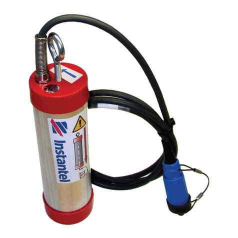
The Triaxial Borehole Geophone is designed to be
lowered into a borehole to measure vertical, transverse and
longitudinal ground vibrations.
Each Triaxial Borehole Geophone is coupled with a Micromate
Base Unit and calibrated to the same industry standard as the
Micromate Base Unit, namely:
ISEE
BOREHOLE
GEOPHONE
DIN
BOREHOLE
GEOPHONE
SWB
BOREHOLE
GEOPHONE
SWP
BOREHOLE
GEOPHONE
PART NUMBER 721A2401
Coupled to the
ISEE base unit
721A2402
Coupled to the
ISEE base unit
721A2401
Coupled to the
DIN base unit
721A2402
Coupled to the
DIN base unit
721A2401
Coupled to the
SWB base unit
721A2402
Coupled to the
SWB base unit
721A2401
Coupled to the
SWP base unit
721A2402
Coupled to the
SWP base unit
RESPONSE
STANDARD ISEE - 2017 DIN 45669-1
CLASS 1
SS4604866
2011 (SWB)
SS025211
(SWP)
FREQUENCY
RANGE 2 - 250 Hz 1 - 315 Hz 5 - 300 Hz 2 - 150 Hz
VELOCITY
RANGE
Up to 254 mm/s
(10 in/s)
Up to 254 mm/s
(10 in/s)
Up to 254 mm/s
(10 in/s)
Up to 254 mm/s
(10 in/s)
RESOLUTION 0.00788 mm/s
(0.00031 in/s)
0.00788 mm/s
(0.00031 in/s)
0.00788 mm/s
(0.00031 in/s)
0.000788 mm/s
(0.000031 in/s)
SENSOR
DENSITY
1.73 g/cc
(108 lbs/ft3)
1.73 g/cc
(108 lbs/ft3)
1.73 g/cc
(108 lbs/ft3)
1.73 g/cc
(108 lbs/ft3)
CABLE LENGTH 30 m
(100 ft)
75 m
(250 ft)
30 m
(100 ft)
75 m
(250 ft)
30 m
(100 ft)
75 m
(250 ft)
30 m
(100 ft)
75 m
(250 ft)
MAXIMUM CABLE
LENGTH
1,000 m
(3,250 ft)
1,000 m
(3,250 ft)
1,000 m
(3,250 ft)
1,000 m
(3,250 ft)
REQUIRED
SOFTWARE
THOR
Compliance
THOR
Compliance
THOR
Compliance
THOR
Compliance
www.instantel.com
Instruction Sheet
2Instantel
INCORRECT
INSTALLATION
CORRECT
INSTALLATION
Physical Installation
Installing the Triaxial Borehole Geophone requires a minimum borehole diameter of 76.2 mm (3 inches).
1. Thread a steel cable through the Triaxial Borehole Geophone’s mounting eyelet bolt and bind securely.
Note: DO NOT use the connecting cable to lower or raise the geophone as this may damage the cable.
2. Point the arrow located on the top of the geophone in the direction of the event.
3. Maintain this orientation while lowering into the borehole and ensure that the geophone is at a 90° angle.
4. Once positioned, connect the Triaxial Borehole Geophone cable and run a sensor check.
5. Maintaining the geophone’s 90° angle, carefully ll in the hole with cement, grout, or sand to secure its
orientation.
6. Repeat the sensor check to ensure the sensor has not moved and all channels still pass the test.
721U2401 Rev 04 - Product specications are subject to change
Toll Free (N.A.): 1.800.267.9111
Telephone: 1.613.592.4642
Email: [email protected]
www.instantel.com
Warranty
Instantel products come with a one-year warranty. Monitoring units and sensors will have the warranty extended for a second year if they are returned
to the Instantel factory for service and calibration within 30 days of the ‘Next Calibration’ date printed on the calibration label located on the product.
If within a period of one year from the date of shipment to a customer, the instrument fails to perform in accordance with Instantel’s published
specications and the operator’s manual, due to a defect in materials or workmanship, it will be repaired or replaced at Instantel’s option, free of
charge. This warranty is void if the equipment has been dismantled, altered or abused in any way. This warranty is nontransferable.
This warranty does not include any implied warranty of functionality for a particular purpose. Instantel assumes no responsibility for damages of any
description resulting from the operation or use of its products. Since it is impossible to anticipate all of the conditions under which its products will
be used either by themselves or in conjunction with other products, Instantel cannot accept responsibility for the results unless it has entered into a
contract for services which clearly dene such an extension of responsibility and liability.
Any shipments returned directly to Instantel Inc. must have our prior approval and all packages must display the Return of Material Authorization
(RMA) number issued by Instantel. Shipping charges to Instantel’s plant will be paid by the customer and those for return to the customer will be paid
by Instantel.
To protect your warranty, you must complete and return a Warranty Registration Certicate, or complete the online Warranty Registration Form, within
ten days of purchase. Products will be assumed out of warranty if there is no warranty card on le at Instantel. Retain this portion and the proof of
purchase for your records.
EC Warning
This is a Class B product. In a domestic environment this product may cause radio interference in which case the user may be required to take adequate measures.
Example Installation
1. Prepare the borehole geophone
by wrapping the connections with
electrical tape to keep them clean.
2. Drill the borehole and slide the
borehole geophone into place.
3. Fill around the borehole geophone
and cable with gravel pack.
4. Fill the hole with cement. 5. Hole lled with connectors ready. 6. Borehole geophone location clearly
marked with monitoring unit placed
in a secure lock box.
Monitoring Unit Setup
Conguring a Micromate Base Unit (ISEE, DIN, SWB, SWP) with a Triaxial Borehole Geophone follows the
same procedure as the Standard Triaxial Geophone. For complete details, please refer to the Micromate
Operator Manual and THOR Operator Manual.
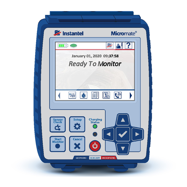

This manual suits for next models

1

Other Instantel Measuring Instrument manuals

Instantel Micromate User manual

Instantel

Instantel Micromate User manual

Instantel BlastMate II User manual

Instantel

Instantel BlastMate II User manual

Instantel Micromate Instruction Manual

Instantel

Instantel Micromate Instruction Manual

Instantel Blastmate III User manual

Instantel

Instantel Blastmate III User manual

Instantel MICROMATE ISEE BOREHOLE GEOPHONE User manual

Instantel

Instantel MICROMATE ISEE BOREHOLE GEOPHONE User manual

Instantel 716A0401 User manual

Instantel

Instantel 716A0401 User manual

Instantel Borehole Triaxial Geophone User manual

Instantel

Instantel Borehole Triaxial Geophone User manual

Instantel Minimate Blaster User manual

Instantel

Instantel Minimate Blaster User manual

Instantel Micromate User manual

Instantel

Instantel Micromate User manual

Popular Measuring Instrument manuals by other brands

MSA SUPREMA Calibration operating manual

MSA

MSA SUPREMA Calibration operating manual

Ocean Optics NeoFox Installation and operation manual

Ocean Optics

Ocean Optics NeoFox Installation and operation manual

horiba LAQUAact  D-74 instruction manual

horiba

horiba LAQUAact D-74 instruction manual

Leica PINMASTER II PRO instructions

Leica

Leica PINMASTER II PRO instructions

Simex SRT-147 user manual

Simex

Simex SRT-147 user manual

Hach TPM870 user manual

Hach

Hach TPM870 user manual

TEM PSD Reader user manual

TEM

TEM PSD Reader user manual

eMitter Basic user manual

eMitter

eMitter Basic user manual

Xylem WTW Turb 430 IR/T operating manual

Xylem

Xylem WTW Turb 430 IR/T operating manual

JENCO 6177M Operation manual

JENCO

JENCO 6177M Operation manual

General UV254SD user manual

General

General UV254SD user manual

Tektronix LA 501 instruction manual

Tektronix

Tektronix LA 501 instruction manual

Keysight PXA X Series Installation note

Keysight

Keysight PXA X Series Installation note

Tektronix P6243 instructions

Tektronix

Tektronix P6243 instructions

Kenko KFM-2100 instruction manual

Kenko

Kenko KFM-2100 instruction manual

RADEX OBSIDIAN Intended use

RADEX

RADEX OBSIDIAN Intended use

Kilews KTM-CSH Operation manual

Kilews

Kilews KTM-CSH Operation manual

Anritsu Network Data Analyzer MD6430A Specifications

Anritsu

Anritsu Network Data Analyzer MD6430A Specifications

manuals.online logo
manuals.online logoBrands
  • About & Mission
  • Contact us
  • Privacy Policy
  • Terms and Conditions

Copyright 2025 Manuals.Online. All Rights Reserved.