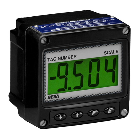
BEKA BA304G User manual

Issue: 5
19th September 2018
BA304G, BA304G-SS,
BA324G & BA324G-SS
intrinsically safe
loop-powered
field mounting indicators
Issue 5

2
1. Description
2. Operation
2.1 Controls
3. Intrinsic safety certification
3.1 ATEX gas certification
3.2 Zones, gas groups & T rating
3.3 4/20mA input
3.4 Certification label information
4. System Design for Gas Hazardous
Areas
4.1 Transmitter loops
4.2 Remote indication
5. Installation
5.1 Location
5.2 GRP models BA304G & BA324G
5.3 Stainless steel models BA304G-SS &
BA324G-SS.
5.4 Installation procedure
5.5 EMC
5.6 Units of measurement and tag marking
on scale card.
6. Configuration and Calibration
6.1 Summary of configuration functions
6.2 Indicator function: FunC
6.3 Resolution: rE5n
6.4 Position of the decimal point: dP
6.5 Calibration using an external current
source: CAL.
6.6 Calibration using internal reference: 5Et
6.7 Bargraph format and calibration: bAr
6.8 Function of the (push-button: C--P
6.9 Tare function: tArE
6.10 Security code: CodE
6.11 Reset to factory defaults: r5Et
6.12 Under and over-range
7. Lineariser
7.1 Lineariser calibration using an external
current source.
7.1.1 Example, Adding break-points
to a new indicator.
7.2 Lineariser calibration using internal
reference.
7.2.1 Example, Adding break-points
to a new indicator.
7.3 Under and over-range
7.4 Lineariser default configuration
8. Maintenance
8.1 Fault finding during commissioning
8.2 Fault finding after commissioning
8.3 Servicing
8.4 Routine maintenance
8.5 Guarantee
8.6 Customer comments
9. Accessories
9.1 Units of measurement and instrument
identification.
9.2 Display backlight
9.2.1 Loop powering the backlight
9.2.2 Separately powering the
backlight
9.3 Alarms
9.3.1 Solid state output
9.3.2 Intrinsic safety
9.3.3 Configuration and adjustment.
9.3.4 Alarm enable: EnbL
9.3.5 Setpoint adjustment:
5P1 and 5P2.
9.3.6 Alarm function: Hi .Lo
9.3.7 Alarm output status: no .nC
9.3.8 Hysteresis: H5tr
9.3.9 Alarm delay: dELA
9.3.10 Alarm silence time: 5iL
9.3.11 Flash display when alarm
occurs: FL5H.
9.3.12 Access setpoint in display
mode: AC5P.
9.3.13 Adjusting alarm setpoints from
the display mode.
9.3.14 Display setpoints on
BA324G-SS bargraph.
9.4 Pipe mounting kit
9.5 Panel mounting kits
9.5.1 BA394G
9.5.2 BA494G
9.5.3 BA494G-SS
9.6 Back-box terminal assembly
Appendix 1 ATEX dust certification
Appendix 2 IECEx gas and dust certification
Appendix 3 ETL and cETL certification
CONTENTS
The BA304G, BA304G-SS, BA324G and BA324G-SS are CE marked to show compliance with the
European Explosive Atmospheres Directive 2014/34/EU and the European EMC Directive 2014/30/EU

3
1. DESCRIPTION
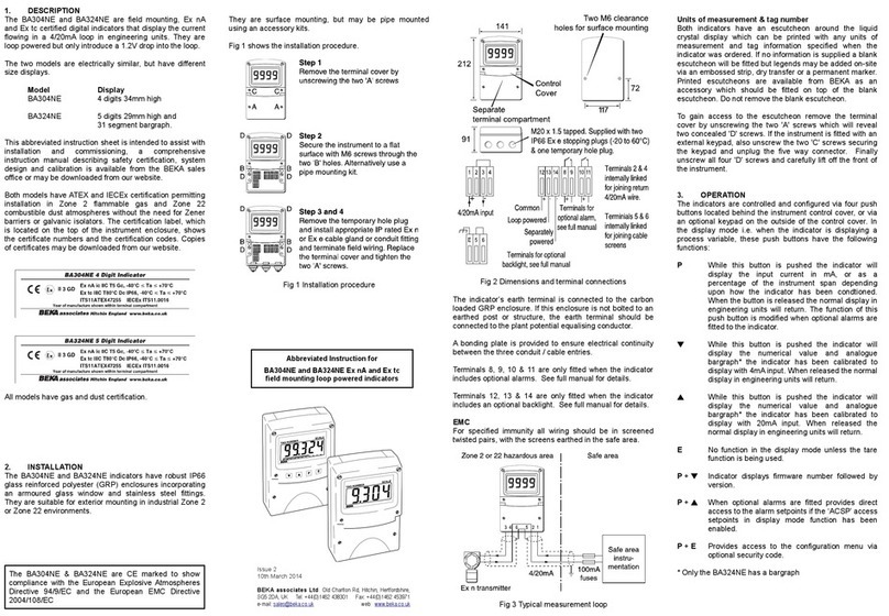
These field mounting, intrinsically safe digital
indicators display the current flowing in a 4/20mA
loop in engineering units. They are loop powered
but only introduce a 1.2V drop, which allows them
to be installed into almost any 4/20mA current
loop. No additional power supply or battery is
required.
The four models are electrically similar, but have
different size displays and enclosure materials.
Model Display
BA304G 4 digits 34mm high in
GRP enclosure.
BA304G-SS 4 digits 34mm high in
stainless steel enclosure.
BA324G 5 digits 29mm high and
31 segment bargraph
in GRP enclosure.
BA324G-SS 5 digits 29mm high and
31 segment bargraph in
stainless steel enclosure.
This instruction manual supplements the
instruction sheet supplied with each instrument.
The main application for all models is to display a
measured variable or control signal in a hazardous
process area. The zero and span of the display
are independently adjustable so that the indicator
can be calibrated to display any variable
represented by the 4/20mA current, e.g.
temperature, flow, pressure or level.
All models have been certified intrinsically safe for
use in gas and dust hazardous areas by Notified
Body Intertek Testing and Certification Ltd and
comply with the European ATEX Directive
2014/34/EU. The EC-Type Examination certificate
specifies that under fault conditions the output
voltage, current and power at the 4/20mA input
terminals will not exceed those specified for simple
apparatus in Clause 5.7 of EN 60079-11, which
simplifies installation and documentation.
For international applications all models have
IECEx certification which is described in
Appendix 2.
For applications in the USA and Canada all models
have ETL and cETL certification which is described
in Appendix 3.
2. OPERATION
Fig 1 shows a simplified block diagram of all
models. The 4/20mA input current flows through
resistor R1 and forward biased diode D1. The
voltage developed across D1, which is relatively
constant, is multiplied by a switch mode power
supply and used to power the instrument. The
voltage developed across R1, which is proportional
to the 4/20mA input current, provides the input
signal for the analogue to digital converter.
Each time a 4/20mA current is applied to the
instrument, initialisation is performed during which
all segments of the display are activated, after five
seconds the instrument displays the input current
using the calibration information stored in the
instrument memory. If the loop current is too low
to power the instrument the indicator will display
the error message LPLo.
Fig 1 Indicator block diagram

4
2.1 Controls
All models are controlled and calibrated via four
front panel push buttons. In the display mode i.e.
when the indicator is displaying a process variable,
these push buttons have the following functions:
(While this button is pushed the
indicator will display the input current
in mA, or as a percentage of the
instrument span depending upon how
the indicator has been configured.
When the button is released the
normal display in engineering units
will return. The function of this push
button is modified when optional
alarms are fitted to the indicator.
&While this button is pushed the
indicator will display the numerical
value and analogue bargraph* the
indicator has been calibrated to
display with a 4mAΦinput. When
released the normal display in
engineering units will return.
*While this button is pushed the
indicator will display the numerical
value and analogue bargraph* the
indicator has been calibrated to
display with a 20mAΦinput. When
released the normal display in
engineering units will return.
)No function in the display mode
unless the tare function is being used.
(+ &Indicator displays firmware number
followed by version.
(+ *Provides direct access to the alarm
setpoints when the indicator is fitted
with optional alarms and the AC5P
access setpoints function has been
enabled.
(+ )Provides access to the configuration
menu via optional security code.
Note: * BA324G and BA324G-SS only
ΦIf the indicator has been
calibrated using the CAL
function, calibration points may
not be 4 and 20mA.
3. INTRINSIC SAFETY CERTIFICATION
All models have ATEX and IECEx gas and dust
certification. This section of the instruction manual
describes ATEX gas certification. ATEX dust and
IECEx approvals are described in Appendixes 1
and 2.
3.1 ATEX gas certification
Notified Body Intertek Testing and Certification Ltd
have issued all the models with a common
EC-Type Examination Certificate number
ITS11ATEX27253X. This confirms compliance
with harmonised European standards and it has
been used to confirm compliance with the
European ATEX Directive for Group II,
Category 1G equipment, Ex ia IIC T5 Ga
Ta = - 40°C to +70°C. The indicators carry the
community mark and, subject to local codes of
practice, may be installed in any of the European
Economic Area (EEA) member countries. ATEX
certificates are also acceptable for installations in
Switzerland and some other countries - see Blue
Book.
This section of the instruction manual describes
ATEX installations in explosive gas atmospheres
conforming with EN60079-14 Electrical
installations design, selection and erection. When
designing systems for installation outside the UK
the local Code of Practice should be consulted.
3.2 Zones, gas groups and T rating
All models have been certified Ex ia IIC T5. When
connected to a suitable system they may be
installed in:
Zone 0 explosive gas air mixture
continuously present.
Zone 1 explosive gas air mixture likely
to occur in normal operation.
Zone 2 explosive gas air mixture not
likely to occur, and if it does
will only exist for a short time.
Be used with gases in groups:
Group A propane
Group B ethylene
Group C hydrogen
In gases that may be used with equipment having
a temperature classification of:
T1 450°C
T2 300°C
T3 200°C
T4 135°C
T5 100°C
At ambient temperatures between -40 and +70°C.
CAUTION installation in Zone 0
When a BA304G or BA324G GRP instrument is
installed in a Zone 0 potentially explosive
atmosphere requiring EPL Ga apparatus, the
instrument shall be installed such that even in the
event of rare incidents, an ignition source due to
impact or friction between the aluminium label and
iron/steel is excluded.
No special conditions apply when a GRP indicator
is installed in Zone 1 or in Zone 2, or for Stainless
steel indicators.

5
This allows all the models to be installed in all gas
Zones and to be used with most common industrial
gases except carbon disulphide and ethyl nitrite
which have an ignition temperature of 95°C.
3.3 4/20mA input
The input safety parameters for the 4/20mA input,
terminals 1 and 3 are:
Ui = 30V dc
Ii = 200mA
Pi = 0.84W
The maximum equivalent capacitance and
inductance between the two 4/20mA input
terminals 1 and 3 is:
Ci = 5.4nF
Li = 0.016mH (0.02mH)
The maximum permitted loop cable parameters
can be calculated by adding these figures to Ci
and Li of other instruments in the loop and
subtracting the totals from the maximum cable
capacitance Co and cable inductance Lo permitted
for the Zener barrier or galvanic isolator powering
the loop.
Although the indicators do not themselves comply
with the requirements for simple apparatus,the
EC-Type Examination Certificate states that for
intrinsic safety considerations, under fault
conditions the output voltage, current and power at
terminals 1 & 3 will not exceed those specified by
clause 5.7 of EN 60079-11 for simple apparatus.
This simplifies the application and intrinsic safety
documentation for a loop into which an indicator is
connected.
3.4 Certification label information
The certification information label is fitted on the
top surface of the instrument assembly. It shows
the ATEX and IECEx certification information and
BEKA associates name and location. Non
European certification information may also be
shown. The instrument serial number and date of
manufacture are recorded on a separate label
inside the instrument enclosure.
Typical certification label
4. SYSTEM DESIGN FOR GAS
HAZARDOUS AREAS.
4.1 Transmitter loops
All the models may be connected in series with
almost any intrinsically safe 4/20mA current loop
and calibrated to display the measured variable or
control signal in engineering units. The indicators
are transparent to HART ®signals.
There are three basic design requirements:
1. The intrinsic safety output parameters of the
4/20mA loop, which are defined by the
Zener barrier or galvanic isolator powering
the loop, must be equal to or less than:
Uo = 30V dc
Io = 200mA
Po = 0.84W
2. The maximum permitted cable capacitance
of the loop, defined by the Zener barrier or
galvanic isolator powering the loop, must be
reduced by 5.4nF and the maximum
permitted cable inductance by 0.02mH.
3. The loop must be able to tolerate the
additional 1.2V required to operate the
indicator. When fitted with an optional
backlight this increases to 5.0V if the
backlight is loop powered. See 9.2.1
Figs 2a and 2b illustrate typical applications in
which an indicator is connected in series with a
2-wire transmitter powered by a Zener barrier and
alternatively by a galvanic isolator.
Fig 2a Loop powered by a Zener barrier

6
Fig 2b Loop powered by a galvanic isolator
4.2 Remote indication
All the models may be driven via an intrinsically
safe interface from a 4/20mA safe area signal to
provide a remote display within a hazardous area.
The type of intrinsically safe interface is not critical,
either a Zener barrier or a galvanic isolator may be
used, providing that Ui, Ii and Pi of the indicator
are not exceeded and the voltage capability of the
4/20mA signal is sufficient to drive the indicator
plus the interface.
When a high integrity earth connection is already
available, a Zener barrier is usually the least
expensive option. If an earth connection is not
available or isolation is required, a galvanic isolator
is the correct choice.
If one side of the 4/20mA current loop may be
earthed, a single channel Zener barrier provides
the lowest cost protection. If the 4/20mA signal is
not isolated, then two Zener barriers, a two
channel Zener barrier or a galvanic isolator must
be used. Fig 3 shows the alternative circuits which
may be used.
Fig 3 Alternative circuits for remote indication
in a hazardous area

7
5. INSTALLATION
5.1 Location
BA304G and BA324G indicators have a GRP
enclosure and BA304G-SS and BA324G-SS
indicators have a 316 stainless steel enclosure.
Both provide IP66 ingress protection after a 7J
impact and have a thick armoured window which
will withstand a 4J impact. They are suitable for
exterior mounting in most industrial on-shore and
off-shore installations.
The indicators should be positioned where the
display is not in continuous direct sunlight. Special
conditions apply for Zone 0 installations, see
section 3.2.
Field wiring terminals are located on the rear of the
indicator assembly as shown in Fig 5c. Indicator
terminals 2 and 4 are internally joined and may be
used for linking the return 4/20mA wire - see
Fig 5c.
The indicators are surface mounting, but may be
pipe mounted using one of the accessory kits
described in section 9.4 or panel mounted as
described in section 9.5.
5.2 GRP models
BA304G and BA324G
The GRP models are fitted with a bonding plate to
ensure electrical continuity between the two
conduit or cable entries. The bonding plate may be
mounted on the inside or outside of the enclosure
and includes an M4 earth stud. If the carbon
loaded GRP enclosure is not bolted to an earthed
post or structure, this earth stud should be
connected to the plant potential equalising
conductor.
An insulated M4 stud is provided in the bottom
right hand corner of the GRP back-box for
interconnecting cable screens.
If field wiring is to be terminated prior to the
installation of the indicator assembly, the GRP
models, BA304G and BA324G, can be supplied
with an optional back-box terminal assembly,
which includes a 4/20mA continuity diode. See
section 9.6 of this manual. This option is not
available for the stainless steel models,
5.3 Stainless steel models
BA304G-SS and BA324G-SS
The stainless steel models have an earthing
terminal in the lower left had side of the back-box.
If the stainless steel enclosure is not bolted to an
earthed post or structure, this earth terminal should
be connected to the plant potential equalising
conductor.
An insulated M4 stud is provided in the bottom
right hand corner of the stainless steel back-box
for interconnecting cable screens.
5.4 Installation Procedure
Fig 4 illustrates the instrument installation
procedure for all models.
A. Remove the indicator assembly by
unscrewing the four captive 'A' screws.
B. Mount the enclosure back-box on a flat
surface and secure with screws or bolts
through the four 'B' holes. Alternatively use
one of the pipe or panel mounting kits
described in sections 9.4 and 9.5.
C. Remove the temporary hole plug and install
an appropriate IP and temperature rated
cable gland or conduit fitting. If two entries
are required, the IP66 stopping plug should
be replaced with an appropriate IP and
temperature rated cable gland or conduit
fitting.
D. Connect the field wiring to the terminals as
shown in Fig 5c. Replace the instrument
assembly on the back-box and evenly tighten
the four 'A' screws.
Fig 4 BA304G, BA304G-SS, BA324G and
BA324G-SS installation procedure

8
Fig 5a Dimensions for BA304G and BA324G.
Fig 5b Dimensions connections
for BA304G-SS and BA324G-SS.
Fig 5c Terminal connections for all models.
5.5 EMC
All models comply with the requirements of the
European EMC Directive 2014/30/EU. For
specified immunity all wiring should be in screened
twisted pairs, with the screens earthed at one point
in the safe area.
An insulated stud is included in the indicator back-
box for joining cable screens.
The optional back-box terminal assembly for GRP
models, which is described in section 9.6, includes
a pair of isolated linked terminals 5 and 6 for
joining cable screens.
5.6 Units of measurement and tag marking
on scale card.
The indicator’s units of measurement and tag
information are shown on a scale card which slides
into the indicator.
New indicators can be supplied with a printed
scale card showing the requested units of
measurement and tag information for no additional
cost. If this information is not supplied when the
indicator is ordered, a blank scale card will be fitted
which can easily be marked on-site with a dry
transfer or a permanent marker. Custom printed
scale cards are available from BEKA associates as
an accessory.
To remove the scale card from an indicator
carefully pull the transparent tab at the rear of the
indicator assembly away from the indicator as
shown in Fig 6a.
Fig 6a Removing scale card

9
Fig 6b Inserting scale card into the
instrument assembly.
To replace the scale card carefully insert it into the
slot on the right hand side of the input terminals as
shown in Fig 6b. Force should be applied evenly
to both sides of the scale card to prevent it
twisting. The card should be inserted until about
2mm of the transparent tab remains protruding.

10
6. CONFIGURATION AND CALIBRATION
All the models are configured and calibrated via
the four front panel push buttons. The
configuration functions are contained in an easy to
use intuitive menu that is shown diagrammatically
in Fig 7.
Each menu function is summarised in section 6.1
and includes a reference to more detailed
information. When the indicator is fitted with
alarms additional functions are added to the menu
which are described in section 9.3
Throughout this manual push buttons are shown
as (,),&or *, and legends are shown in a
seven segment font exactly as displayed by the
indicator e.g. CAL and ALr2.
Access to the configuration menu is obtained by
operating the (and )push buttons
simultaneously. If the indicator security code is set
to the default 0000 the first parameter FunC will be
displayed. If a security code other than the default
code 0000 has already been entered, the indicator
will display CodE. Pressing the (button will clear
this prompt allowing each digit of the code to be
entered using the &and *push buttons and the
(button to move control to the next digit. When
the correct four digit code has been entered
pressing )will cause the first parameter FunC to
be displayed. If the code is incorrect, or a button
is not pressed within twenty seconds, the indicator
will automatically return to the display mode.
Once within the configuration menu the required
parameter can be reached by scrolling through the
menu using the &and *push buttons as shown
in Fig 7. When returning to the display mode
following recalibration or a change to any function,
the indicator will display dAtA followed by 5AVE
while the new information is stored in permanent
memory.
All new indicators are supplied calibrated as
requested at the time of ordering. If calibration is
not requested, indicators will be supplied with the
following default configuration:
Default Configuration
BA304G BA324G
BA304G-SS BA324G-SS
Access code CodE 0000 0000
Function FunC Linear Linear
Display at 4mA 2ero 0.0 0.00
Display at 20mA 5PAn 100.0 100.00
Resolution rE5n 1 digit 1 digit
Bargraph start BarLo ----- 0.00
Bargraph finish BarHi ----- 100.00
(button in display mode C--P %%
Tare tArE Off Off
6.1 Summary of configuration functions
This section summarises each of the main
configuration functions and includes a cross
reference to a more detailed description. Fig 7
illustrates the location of each function within the
configuration menu. The lineariser and the
optional factory fitted alarms are described
separately in sections 7 and 9.3 of this manual.
Display Summary of function
FunC Indicator function
Defines the relationship between the
4/20mA input current and the indicator
display. May be set to:
5td Standard linear relationship
root Square root extraction
Lin 16 segment adjustable
lineariser – see section 7.
See section 6.2
rE5n Display resolution
Defines the resolution of the least
significant display digit. May be set to
1, 2, 5or 10 digits.
See section 6.3
dP Decimal point
Positions a dummy decimal point
between any of the digits or turns it off.
See section 6.4
CAL Calibration of the digital display using
an external current source.
Enables the zero and span of the
indicator to be adjusted using an external
current source such as a calibrator.
When used with an accurate traceable
current source this is the preferred
method of calibration.
See section 6.5
5Et Calibration of display using internal
references.
Enables the zero and span of the
indicator to be adjusted without the need
for an accurate input current or
disconnection from the 4/20mA loop. See
section 6.6
bAr Bargraph format and calibration
Only the BA324G & BA324G-SS have a
bargraph.
The bargraph may be conditioned to start
from left, right or centre of the display, or
it may be disabled. When optional
alarms are fitted it can also display both
alarm setpoints and the measured value.
The bargraph may be calibrated to start
and finish at any value within the
indicator’s calibrated digital display.
See section 6.7
11

12
Display Summary of function
C--P Function of (push button
The indicator may be configured to
display the input current in milliamps, or
the input current as a percentage of the
4/20mA input when the (push button is
operated in the display mode.
See section 6.8
tArE Tare function
When enabled the tare function sets the
indicator display to zero when the )
push button is operated in the display
mode.
See section 6.9
CodE Security code
Defines a four digit numeric code that
must be entered to gain access to the
configuration menu. Default code 0000
disables this security function and allows
unrestricted access to all conditioning
functions.
See section 6.10
r5Et Reset
Contains two sub-functions, ConF which
returns the indicator to the default
conditions shown in section 6.0, and
LtAb which returns the lineariser to the
default conditions shown in section 7.4.
To prevent accidental use both resets
must be confirmed by entering 5urE
before they will be executed.
See section 6.11
6.2 Indicator function: FunC
This configuration function defines the relationship
between the indicator’s 4/20mA input current and
the indicator’s display. Three alternatives are
available:
5td Standard linear relationship
root Square root extraction
Lin 16 segment adjustable lineariser
To reveal the indicator's existing function select
FunC from the configuration menu and press (.
If the function is set as required, press )to return
to the menu, or press the &or *button to
change the setting, followed by the )button to
return to the configuration menu.
5td Linear
Provides a linear relationship between
the 4/20mA indicator input current and
the indicator display.
root Square root extraction
Primarily intended to linearise the square
law 4/20mA output from differential
flowmeters.
For reference, the following table shows
the output current from a non-linearised
differential flowmeter.
% of full flow Current output mA
2.5 4.01
10.0 4.16
25.0 5.00
50.0 8.00
75.0 13.00
100.0 20.00
When the root function is selected the
indicator will display flow in linear units.
Lin 16 segment adjustable lineariser
Enables non-linear variables to be
displayed by the indicator in linear
engineering units. Use of the lineariser is
described in section 7 of this instruction
manual.
6.3 Resolution: rE5n
This function defines the resolution of the least
significant display digit. Decreasing the display
resolution can improve the readability of a noisy
signal. Select rE5n from the menu and press
(which will reveal the current display resolution.
To change the resolution press the &or *
button to select 1,2,5or 10 digits, followed by the
)button to enter the selection and return to the
configuration menu.

13
6.4 Position of the decimal point: dP
A dummy decimal point can be positioned between
any of the digits or it may be absent. To position
the decimal point select dP from the menu and
press (. The decimal point can be moved by
pressing the &or *push button. If a decimal
point is not required it should be positioned beyond
the most or least significant digit. When
positioned as required press the )button to enter
the selection and return to the configuration menu.
6.5 Calibration using an external
current source: CAL
This function enables the zero and span of the
indicator to be adjusted using an external
calibrated current source. When used with an
accurate traceable current source this is the
preferred method of calibration.
Zero is the indicator display with 4mA input
Span is the indicator display with 20mA input
To calibrate the indicator select CAL from the
configuration menu and press (. The indicator
will display 2Ero which is a request for a 4mA input
current. Adjust the external current calibrator to
4.000mA and again press (which will reveal the
current zero display. The flashing digit of the
indicator display can be changed by pressing the
&or *buttons, when set as required pressing
(will transfer control to the next digit. When all
the digits have been adjusted, press )to enter
the new zero and return to the 2Ero prompt .
Pressing the *button will cause the indicator to
display 5PAn which is a request for a 20mA input
current. Adjust the external current calibrator to
20.000mA and again press (which will reveal
the existing span display. The flashing digit of the
indicator display can be changed by pressing the
&or *buttons, when set as required pressing
(will transfer control to the next digit. When all
the digits have been adjusted press )to enter
the new span and return to the 5PAn prompt.
Finally press )again to return to the
configuration menu.
Notes:
a. The indicator input current must be adjusted to
the required value before the zero and span
functions are entered by pressing the
(button.
b. Indicators may be calibrated at currents other
than 4 and 20mA, within the range 3.8 to
21.0mA providing the difference between the
two currents is greater than 4mA. If these
conditions are not complied with, the indicator
displays FaiL and aborts the calibration.
c. If the zero current is greater than the span
current the instrument will be reverse acting i.e.
an increasing input current will cause the
display to decrease.
6.6 Calibration using internal reference: 5Et
Using the 5Et function the indicator can be
calibrated without the need to know the value of
the 4/20mA input current, or to disconnect the
indicator from the 4/20mA loop.
When using the 5et function the indicator’s internal
reference is used to simulate a 4mA and 20mA
input current.
Zero is the display with a simulated 4mA input
Span is the display with a simulated 20mA input
To calibrate the indicator display select 5Et from
the configuration menu and press (.The
indicator will display 2Ero, pressing (again will
reveal the current display at 4mA. The flashing
digit can be adjusted by pressing the &or *
buttons, when the flashing digit is correct pressing
(will transfer control to the next digit. When all
the digits have been adjusted, press )to return
to the 2Ero prompt.
To adjust the display at 20mA, press the *button
which will cause the indicator to display 5PAn,
pressing (will then reveal the indicator’s existing
display at 20mA. The flashing digit can be
adjusted by pressing the &or *buttons, when
the flashing digit is correct pressing (will transfer
control to the next digit. When all the digits have
been adjusted press )to return to the 5PAn
prompt followed by )to return to the 5Et prompt
in the configuration menu.
6.7 Bargraph format and calibration: bAr
Only the BA324G and BA324G-SS have a
bargraph.
In addition to a five digit numerical display the
BA324G has a 31 segment analogue bargraph
which may be configured to start and finish
anywhere within the indicator’s numerical display
range.
To configure the bargraph select bAr from the
configuration menu and press (. The indicator
will display tYPE, pressing (again will reveal the
existing bargraph justification which can be
changed to one of the following four or five options
using the &or *button:
Bargraph justification starts from
LEFt Left end of display
CEntr Centre of display
riGHT Right end of display
Alr5P Only with alarms - see section 9.3.14
oFF Bargraph disabled
When set as required press )to return to the
tYPE sub-function prompt.

14
The indicator’s digital display at which the
bargraph starts is defined by the bArLo sub-
function which is selected by pressing the *
button followed by the (button which will reveal
the current indicator display at which the bargraph
starts. The flashing digit can be adjusted by
pressing the &or *buttons, when set as
required pressing (will transfer control to the
next digit. When all the digits have been adjusted,
press )to return to the bArLo prompt from which
bArHi which defines the finishing point of the
bargraph can be selected by pressing the *
button. bArHi is adjusted in the same way as
bArLo. When set as required, pressing )twice
will return the display to the bAr prompt in the
configuration menu.
Note: bArLo must be set lower than bArHi,
incorrect setting is indicated by the bargraph scale
flashing with a single bargraph segment activated.
6.8 Function of the (push-button: C--P
When the indicator is in the display mode,
operating the (push button will display the input
current in milliamps, or the displayed value as a
percentage of the difference between the
displayed values at 4mA and 20mA inputs.
To check or change the function of the (push
button select C--P from the configuration menu
and press (to reveal the current setting.
Pressing the &or *button will toggle the setting
between 4-20 the current display in milliamps and
PC the percentage display. When set as required
press )to return to the C--P prompt in the
configuration menu.
6.9 Tare function: tArE
The tare function is primarily intended for use with
a weighing system. When the indicator is in the
display mode and the tare function is activated,
pressing the )button for more than three
seconds will zero the indicator’s digital display and
activate the tare annunciator. On the BA324G and
BA324G-SS, the bargraph remains linked to the
digital display when the tare function is activated.
Subsequent operation of the )push button for
less than 3 seconds will return the indicator to the
gross display and deactivate the tare annunciator.
To check or change the tare function select tARE
from the configuration menu and press (to
reveal the current setting. Pressing the &or *
button will toggle the setting between on and oFF.
When set as required press )to return to the
tARE prompt in the configuration menu.
6.10 Security code: CodE
Access to the instrument configuration menu may
be protected by a four digit security code which
must be entered to gain access. New instruments
are configured with the default security code 0000
which allows unrestricted access to all
configuration functions.
To enter a new security code select CodE from the
configuration menu and press (which will cause
the indicator to display the existing security code
with one digit flashing. The flashing digit can be
adjusted using the &or *push buttons, when
set as required operating the (button will
transfer control to the next digit. When all the
digits have been adjusted press )to return to the
CodE prompt in the configuration menu. The
revised security code will be activated when the
indicator is returned to the display mode. Please
contact BEKA associates sales department if the
security code is lost.
6.11 Reset to factory defaults: r5Et
This function enables the indicator and the
lineariser to be quickly returned to the factory
default configurations shown in sections 6.0 and
7.4.
To reset the indicator or lineariser select r5Et from
the configuration menu and press (, the indicator
will display one of the reset options ConF or LtAb.
ConF Resets the indicator to defaults
LtAb Resets the lineariser to defaults
Using the &or *push button select the
required sub-function and press (. To prevent
accidental resetting the request must be confirmed
by entering 5urE.Usingthe*button set the first
flashing digit to 5and press (to transfer control
to the second digit which should be set to u.
When 5urE has been entered pressing the )
button will reset the selected configuration menus
and return the display to the r5Et function in the
configuration menu.
6.12 Under and over-range
If the numerical display range of the indicator is
exceeded, all the decimal points will flash as
shown below:
BA304G BA324G
BA304G-SS BA324G-SS
Underrange -9 .9.9.9-9.9.9.9.9
Overrange 9.9.9.99.9.9.9.9
Although not guaranteed, most indicators will
continue to function normally with an input current
between 1.8mA and 4mA, at lower currents the
instrument will display LPLo before it stops
functioning.
Under or over-range of the BA324G and the
BA324G-SS bargraph is indicated by a flashing
arrow at the appropriate end of the bargraph.

15
7. LINEARISER
A sixteen segment, seventeen break-point (0 to 16)
lineariser may be selected in the FunC section of
the configuration menu. The position of each
break-point is fully adjustable so that the slope of
the straight line between break-points can be set to
compensate for input non-linearity, thus allowing
the indicator to display non-linear process
variables in linear engineering units. Each break-
point must occur at a current greater than the
preceding break-point and less than the following
break-point, in the range 3.8 to 21.0mA. If this
requirement is not observed when configuring the
lineariser the indicator will display FaiL and the
configuration adjustment which produced the error
message will be ignored. Fig 8 shows a typical
linearised indicator characteristic.
Fig 8 shows a typical linearising characteristic
Selecting Lin in the FunC section of the
configuration menu activates the lineariser, this
does not change the configuration menu shown in
Fig 7, but the CAL and 5Et functions are extended
as shown in Fig 9. As with a linear indicator,
calibration of the lineariser may be performed with
an external current source using the CAL function,
or with the internal reference using the 5Et
function.
The lineariser calibration is retained irrespective of
how the indicator function FunC is subsequently
changed. It is therefore possible to select and
deselect the lineariser without having to
reconfigure it each time.
The lineariser calibration may be reset to the
factory default settings without changing the
indicator configure using the LtAb function
described in section 6.11.
7.1 Lineariser calibration using an external
current source.
This method allows direct calibration of the
lineariser with an external current source and is
the preferred method when traceability is required.
If the exact system non-linearity is unknown, this
method also allows direct calibration from the
variable to be displayed. e.g. the output from a
level sensor in an irregular tank may be displayed
in linear volumetric units by filling the tank with
known incremental volumes and calibrating the
indicator to display the sum of the increments at
each break-point.
The number of break-point required should first be
entered using the Add and dEL functions. In both
these sub-functions the indicator initially displays
the current break-point and the total number of
break-points being used as shown below.
Display Summary of function
Add Add a break-point
Adds a new break-point before the
displayed break-point. The calibration of
existing break-points is not changed, but
the identification number of all
subsequent break-points is increased by
one.
dEL Remove a break-point
Removes the displayed break-point and
joins the preceding break-point to the
following break-point with a straight line.
The identification number of all
subsequent break-points is decreased by
one.
To add a break-points use the &or *button to
select CAL from the configuration menu and press
(which will result in the Add sub-function prompt
being displayed. To enter the sub-function press
(which will reveal the current break-point and
the total number of break-points which have
already been entered. When adding a break-point
the insertion position can be selected using the &
and *push buttons followed by (push button
to insert the additional break-point. In previously
uncalibrated linearisers each new break-point
should be added in front of the highest existing
break-point, if this sequence is not followed a FaiL
message will occur in the Pt5 function. See
example in section 7.1.1.

16

17
The delete break-point sub-function dEL operates
in exactly the same way as the Add sub-function
described above. Once within the dEL sub-
function each time the (button is pressed a
break-point is removed. When deleting a break-
point from a calibrated indicator, the break-point to
be deleted can be selected using the &and *
push buttons. The minimum number of break-
points is 2, break-points 0:1 and 1:1.
When the required number of linearising break-
points has been entered, return to the linearisation
sub-menu by pressing ). The indicator will
display the Add or dEL prompt depending upon the
last function used. Using the Pt5 sub-function the
input current at which each break-point occurs and
the corresponding indicator display may now be
defined.
Using the &or *button select the Pt5 function
in the sub-menu and press (to enter the function
which will display the first break-point 0 : n, where n
is the total number of linearising break-points
entered - see Fig 9. The selected linearising
break-point can be changed using the &and *
buttons. When the required linearising break-point
has been selected set the indicator input current to
the exact value at which the break-point is required
and press (*. Using the &and *buttons and
the (button to move between digits, enter the
required indicator display at this break-point.
When set as required, press the )push button to
enter the required indicator display and return to
the sub-menu from which the next break-point can
be selected.
When all the break-points have been calibrated
pressing )twice will return the indicator to the
‘CAL’ function in the configuration menu.
Note: * The indicator input current must be
adjusted to the required value before the
(button is operated to enter the required
indicator display.
Error message
If during calibration the indicator displays
aFAiL error message the current at which
the selected break-point is being set is not
above the proceding break-point or is not
below the following break-point.
7.1.1 Example
Adding break-points to a new indicator
When adding break-points to a new indicator, or to
a lineariser following resetting to the factory
defaults using the LtAb function described in
section 6.11, each additional break-point should be
added before the highest existing breakpoint.
The first additional break-point should be added
before the default break-point 1 :1 which will result
in a display of 1 : 2. If more new break-points are
required, using the *button select the new
highest break-point 2 : 2 and add the second
additional break-point by operating the (push
button which will result in a display of 2 : 3. Repeat
the sequence until the required number of break-
points has been entered.
The input current and at which each break-point
occurs and the corresponding indicator display
may now be entered as described above.
7.2 Lineariser calibration using the internal
reference.
The 5Et function enables the lineariser to be
calibrated without the need for an accurate
external current source. Throughout the
calibration the indicator input current may be any
value between 4 and 20mA.
The 5Et functions contains four sub-functions.
Display Summary of function
Add Add a break-point
Adds a new break-point before the
displayed break-point. The calibration of
existing break-points is not changed, but
the identification number of all
subsequent break-points is increased by
one.
dEL Remove a break-point
Removes the displayed break-point and
joins the preceding segment to the
following segment with a straight line.
The identification number of all
subsequent break-points is decreased by
one.
in Defines the current at which break-point
occurs.
Enables the required current at each
break-point to be defined without having
to input an accurate input current to the
indicator.
di5P Defines indicator display at break-point.
Enables the indicator display at each
break-point to be defined.
The number of break-points required should first
be entered using the Add and dEL sub-functions.
In both these sub-functions the indicator initially
displays the current break-point and the total
number of break-points being used as shown
below.

18
To add a break-point using the &or *button
select 5Et from the configuration menu and press
(which will result in the Add sub-function prompt
being displayed. To enter the sub-function press
(which will reveal the current break-point and
the total number of break-points which have
already been entered. When adding a break-point
the insertion position can be selected using the &
and *push buttons followed by (push button
to insert the additional break-point. In previously
uncalibrated linearisers each new break-point
should be added in front of the highest existing
break-point, if this sequence is not followed a FaiL
message will occur when the break-points are
calibrated. See example in section 7.2.1.
The delete a break-point, sub-function dEL
operates in exactly the same way as the Add sub-
function described above. Once within the dEL
function each time the (button is pressed a
break-point is removed. When deleting a break-
point from a calibrated indicator, the break-point to
be deleted can be selected using the &and *
push buttons. The minimum number of break-
points is 2, break-points 0:1 and 1:1.
When the required number of linearising break-
points has been entered, return to the linearisation
sub-menu by pressing ). The indicator will
display the Add or dEL prompt depending upon the
last sub-function used. The indicator input current
and corresponding indicator display at each break-
point, which is the segment finishing point as
shown in Fig 9, can now be entered using the in
and di5P sub-functions.
Using the &or *button select in from the sub-
menu and press (which will reveal the starting
point for the first segment 0 : n, where n is the total
number of break-points entered. Press (and use
the &and *buttons and the (buttontomove
between digits, to enter the input current in
milliamps at which the first break-point is required,
usually 4.000mA. When set as required, press )
to return to the 0 : n prompt from which the next
break-point can be selected using the &and *
buttons. When the required break-point has been
selected press (and enter the indicator input
current at which this break-point is required using
the &and *buttons and the (buttontomove
between digits. Repeat this procedure until the
indicator input current at all the break-points has
been defined and then return to the in sub-
function by pressing the )button.
The corresponding indicator display at each of the
break-points can now be defined using the di5P
sub-function. Using the &and *buttons select
the di5P sub-function and press (which will
reveal the starting point for the first break-point 0:n,
where nis the total number of break-points
entered.
Press (and use the &and *buttons and the
(button to move between digits, to enter the
required indicator display at the first break-point.
When set as required, press )to return to the 0:n
prompt from which the next break-point can be
selected using the &or *buttons. When the
required break-point has been selected press
(and set the required indicator display at this
break-point.
Repeat this procedure until the indicator display at
all the break-points has been defined and then
return to the 5Et function in the configuration menu
by pressing the )button twice.
Error message
If during calibration the indicator displays
aFAiL error message the current at which
the selected break-point is being set is not
above the proceding break-point or is not
below the following break-point.
7.2.1 Example
Adding break-points to a new indicator
When adding break-points to a new indicator, or to
a lineariser following resetting to the factory
defaults using the LtAb function described in
section 6.11, each additional break-point should be
added before the highest existing breakpoint.
The first additional break-point should be added
before the default break-point 1:1 which will result
in a display of 1:2. If more new break-points are
required, using the *button select the new
highest break-point 2:2and add the second
additional break-point by operating the (push
button which will result in a display of 2:3. Repeat
the sequence until the required number of break-
points has been entered.
7.3 Under and over-range
The lineariser does not change the under and
over-range indication described in section 6.12. At
input currents below that specified for the first
break-point 0:n, the indicator will continue to use
the specified slope of the first segment.
At input currents above that specified for the last
break-point n:n, the indicator will continue to use
the slope specified for the last lineariser segment.
7.4 Lineariser default configuration
When the lineariser is reset to the factory defaults
using the LtAb function described in section 6.11,
the defaults conditions are:
Indicator display
BA304G BA324G
BA304G-SS BA324G-SS
First break-point 0 :1 4mA 0.0 0.00
Second break-point 1 :1 20mA 100.0 100.00

19
8. MAINTENANCE
8.1 Fault finding during commissioning
If an indicator fails to function during
commissioning the following procedure should be
followed:
Symptom Cause Solution
No display Incorrect
wiring
Check wiring
There should be
0.6 to 1.2V
between terminals
1 & 3 with terminal
1 positive.
With an optional
backlight loop
powered, there
should be 3.4 to 5V
between terminals
3 & 12 with terminal
12 positive.
No display
0V between
terminals 1 & 3.
Incorrect
wiring or no
power supply
Check supply
voltage and voltage
drop caused by all
the instruments in
the loop.
All decimal points
flashing.
Overrange or
underrange if
-ve sign is
displayed.
Recalibrate the
numerical display.
Unstable display 4/20mA input
is noisy.
Eliminate ripple on
4/20mA power
supply and/or
decrease indicator
resolution.
Unable to enter
configuration
menu.
Incorrect
security code
entered.
Enter correct
security code, or
contact BEKA if the
code has been lost.
8.2 Fault finding after commissioning
ENSURE PLANT SAFETY BEFORE
STARTING MAINTENANCE
Live maintenance is permitted on
intrinsically safe equipment installed in a
gas hazardous area, but only certified test
equipment should be used unless a gas
clearance certificate is available.
If an indicator fails after it has been functioning
correctly, follow the procedure shown in section
8.1. If this does not reveal the cause of the fault, it
is recommended that the instrument is replaced.
This can be done without disconnecting power, but
while the indicator is disconnected the 4/20mA
loop will be open circuit.
8.3 Servicing
All BA304G, BA304G-SS, BA324G and
BA324G-SS loop powered indicators are
interchangeable if the required optional backlight
and alarms are fitted. A single spare instrument
may quickly be recalibrated to replace any
instrument that is damaged or fails. No attempt
should be made to repair instruments at
component level.
We recommend that faulty instruments are
returned to BEKA associates or to your
local BEKA agent for repair.
8.4 Routine maintenance
The mechanical condition of the instrument and
electrical calibration should be regularly checked.
The interval between inspections depends upon
environmental conditions.
8.5 Guarantee
Indicators which fail within the guarantee period
should be returned to BEKA associates or our local
agent. It is helpful if a brief description of the fault
symptoms is provided.
8.6 Customer comments
BEKA associates is always pleased to receive
comments from customers about our products and
services. All communications are acknowledged
and whenever possible, suggestions are
implemented.

20
9. ACCESSORIES
9.1 Units of measurement & instrument
identification.
New indicators are supplied with a printed scale
card showing the units of measurement and tag
information specified when the instrument was
ordered. If this information was not supplied a
blank scale card will be supplied which can easily
be marked on-site with a dry transfer or a
permanent marker.
Custom printed scale cards are available as
accessories and may be easily fitted as shown in
section 5.6 of this manual.
All models can also be supplied with a blank or
custom laser engraved stainless steel legend plate
- see Figs 5a and 5b. The plate, which after
installation is visable from the front of the
instrument, is supplied loose with two fixing screws
for securing it to the rear of the instrument's back-
box. This plate can typically accommodate:
1 row of 5 alphanumeric characters 10mm high
or 1 row of 6 alphanumeric characters 7mm high
or 2 rows of 10 alphanumeric characters 5mm high
9.2 Display backlight
All models can be supplied with a factory fitted
backlight that may be loop or separately powered.
When loop powered the backlight produces green
background illumination enabling the display to be
read at night or in poor lighting conditions. No
additional power supply, intrinsic safety interface or
field wiring are required, but the indicator voltage
drop is increased. When separately powered the
backlight is brighter, but an additional intrinsic
safety interface and field wiring are required.
Fig 10 Terminals for optional backlight
9.2.1 Loop powering the backlight
The backlight is loop powered by connecting it in
series with the indicator’s 4/20mA input as shown
in Fig 11, which increases the maximum indicator
voltage drop from 1.2 to 5V.
Fig 11 Backlight loop powered
The input intrinsic safety parameters of the
combined indicator and backlight are the same as
for the indicator alone. The EC-Type Examination
Certificate states that for intrinsic safety
considerations, under fault conditions the output
voltage, current and power of the combined
indicator and backlight terminals 12 & 3 will not
exceed those specified by clause 5.7 of
EN 60079-11 for simple apparatus,which
simplifies system design and documentation.
Providing the increased voltage drop can be
tolerated the intrinsic safety and system design
described in sections 3 and 4 of this manual
remain valid with the backlight loop powered.
This manual suits for next models
3
Table of contents
Other BEKA Measuring Instrument manuals
Popular Measuring Instrument manuals by other brands

Ahlborn
Ahlborn ALMEMO 500 Supplementary instructions manual

PCE Instruments
PCE Instruments PCE-N24 Series user manual

American Innovations
American Innovations Bullhorn RM4200 Series user guide

Michell Instruments
Michell Instruments XTP601 user manual

DeFelsko
DeFelsko PosiTector 6000 instruction manual

Skyla
Skyla HB1 Operator's manual

Oxylitre
Oxylitre F1680 Series Instructions for use

Baumer
Baumer Hubner Berlin TDPZ 0,2+ESL Installation and operating instructions

POSITECTOR
POSITECTOR SPG quick guide

visilab
visilab AK30 Technical notes

MKS
MKS Spectra-Physics InSight X3+ Pre-installation guide

M-system
M-system 47D Series reference guide