Vzense DCAM550 User manual

1
Vzense DCAM550 ToF Camera
User Manual
DCAM550-U DCAM550-P DCAM550-E

2
Table of Contents
1General Information............................................................................................ 4
1.1 Terms of Use............................................................................................ 4
2Precautions ........................................................................................................ 6
2.1 Safe Usage Instructions ........................................................................... 6
2.2 Power....................................................................................................... 6
2.3 Usage....................................................................................................... 7
2.4 Temperature............................................................................................. 7
3Specifications and Requirement......................................................................... 8
3.1 General Specifications.............................................................................. 8
3.2 Electrical Specifications............................................................................ 9
3.2.1 Recommended Operating Conditions............................................. 9
3.2.2 Power Consumption....................................................................... 9
3.2.3 Absolute Maximum Ratings............................................................ 9
3.3 DCAM550-P Mechanical Specifications.................................................. 10
3.4 DCAM550-U Mechanical Specifications ..................................................11
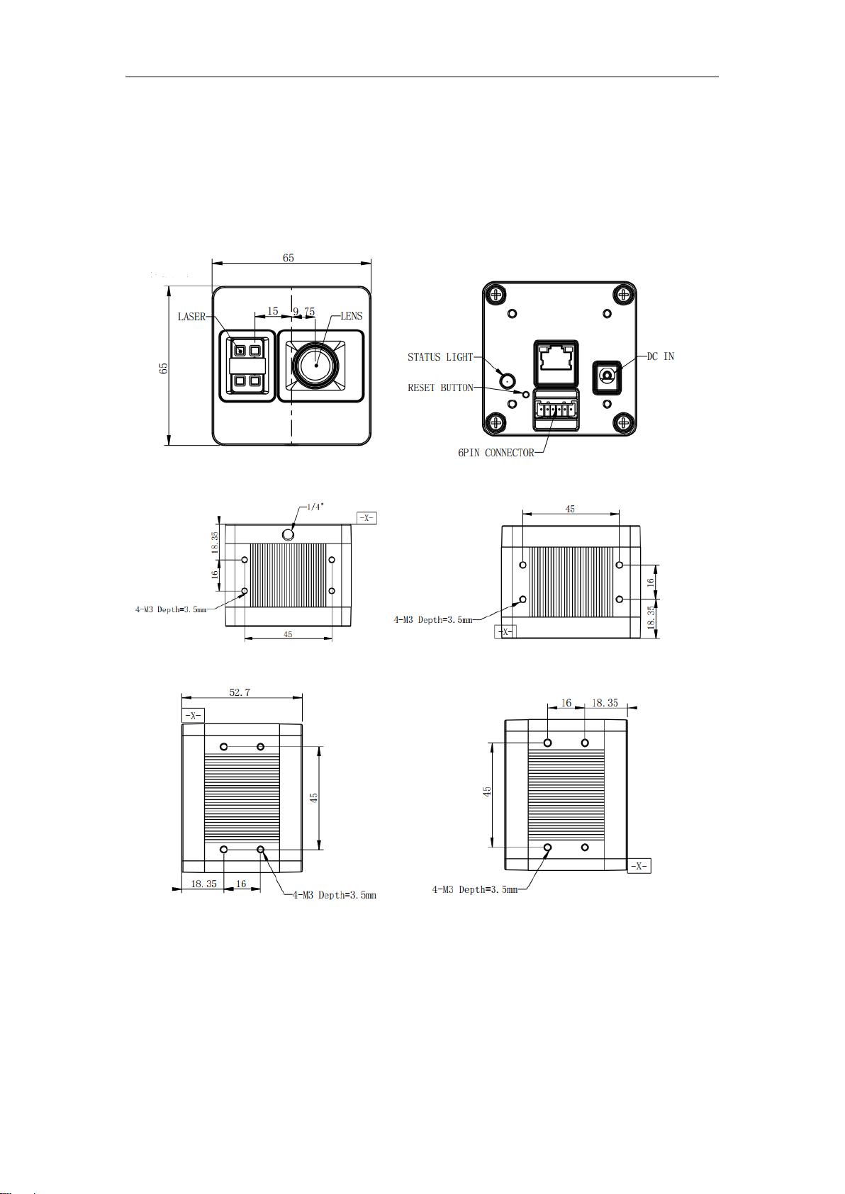
3.5 DCAM550-E Mechanical Specifications ................................................. 12
3.6 Optical Specifications............................................................................. 13
3.6.1 Field of View................................................................................. 13
3.6.2 Wavelength of the VCSEL............................................................ 13
3.7 Working Condition Requirements........................................................... 14
3.7.1 Hardware Requirements............................................................... 14
3.7.2 Software Requirements................................................................ 14
3.7.3 Environmental Requirements ....................................................... 15
3.7.4 Coordinate of the Camera System ............................................... 15
4Interface with Host............................................................................................ 17
4.1 DCAM550-U........................................................................................... 17
4.2 DCAM550-P........................................................................................... 17
4.3 6pin Connector for DCAM550-U/P.......................................................... 18
4.4 Type A USB2.0 Connector for DCAM550-U............................................ 19
4.5 RJ45 Ethernet Connector for DCAM550-P............................................. 20
4.6 DCAM550-E........................................................................................... 20
4.7 LED Indication........................................................................................ 24
4.8 IP Reset Button for DCAM550-P ............................................................ 26
5Principle of Time of Flight ................................................................................. 27
5.1 Vzense ToF Principle.............................................................................. 27
5.2 Noise Factors......................................................................................... 27
5.2.1 Ambient Light............................................................................... 27
5.2 Multipath Propagation............................................................................. 27
5.3 Reflectivity of the Target......................................................................... 28
5.4 Scattering Effect..................................................................................... 28
6Installation........................................................................................................ 29
6.1 Hardware Installation.............................................................................. 29

3
6.1.1 USB2.0 Mode Installation (DCAM550-U Only) ............................. 29
6.1.2 100M Ethernet Installation (DCAM550-P and DCAM550-E)......... 29
6.1.3 Power Over Ethernet Mode Installation........................................ 30
6.2 Software Installation............................................................................... 32
6.2.1 How to get.................................................................................... 32
6.2.2 Graphic Tool on windows.............................................................. 32
6.2.3 Frameviewer ................................................................................ 33
6.3 Firmware Upgrade.................................................................................. 33
6.4 Product State Machine........................................................................... 34
6.5 Software Command Set ......................................................................... 36
6.6 USB Connection..................................................................................... 36
7Features........................................................................................................... 37
7.1 Slave Trigger Mode ................................................................................ 37
7.2 Range Customization............................................................................. 37
7.3 Wide Dynamic Range............................................................................. 38
7.4 Data Filtering.......................................................................................... 39
7.5 IR Image................................................................................................. 39
8Camera Operation on Frameviewer.................................................................. 41
8.1 Main screen............................................................................................ 41
8.1.1 Image area................................................................................... 42
8.1.2 Command and information area................................................... 42
8.2 Connect devices..................................................................................... 43
8.3 2D view .................................................................................................. 43
8.3.1 Depth Image................................................................................. 43
8.3.2 IR Image ...................................................................................... 44
8.4 3D image store....................................................................................... 44
8.5 Camera Control...................................................................................... 45
8.5.1 Mode switch................................................................................. 45
8.5.2 Range change.............................................................................. 45
8.6 WDR ...................................................................................................... 46
9DCAM550 Accessories and Package ............................................................... 49
10 Customization Service............................................................................... 53
Appendix................................................................................................................. 53
Manufacturer............................................................................................. 53
Factory...................................................................................................... 53
FCC Statement ................................................................................................ 54
Revision History...................................................................................................... 55

4
1 General Information
The purpose of this document is to familiarize the customer with the correct operation
of the Vzense ToF DCAM550 products family. This document provides important
information about the camera’s features, hardware specification, safe use of the
camera, and installation procedures.
DCAM550 product family is a series of products designed by Vzense company. It has
three sub-series, DCAM550-U, DCAM550-P, DCAM550-E.
DCAM550-U refers to the model with USB connection.
DCAM550-P refers to the model with Power over Ethernet function via standard RJ45
Ethernet interface.
DCAM550-E refers to the model with IP67 Enclosure, also support Power over
Ethernet function.
1.1 Terms of Use
Vzense offers a 1-year-warranty for this ToF product.
Warranty Information
Please do follow the guidelines below when using the Vzense camera:
Do not remove the product’s serial number label
Warranty will be void, if the label is damaged or removed and the serial number can’t
be read from the camera’s registers.
Do not disassemble the product housing
Do not disassemble the housing. Touching any internal components may damage the
products.
Prevent anyobjects orsubstances from entering the product housing, otherwise
the product may fail or damaged.
Avoid electromagnetic areas
Do not use the camera near strong electromagnetic areas. Prevent the product from
electrostatic charging.
Transport in original packaging
Transport and store the camera in its original packaging only. Suggest not to discard
the packaging.
Clean with care
If you have to clean the housing of the camera, follow the guidelines in the notice as

5
below:
Use a soft, dry cloth that won’t generate static during cleaning;
To remove tough stains, use a soft cloth dampened with a small amount of neutral
detergent(Pure water or alcohol); after that wipe dry;
Make sure no any residual detergent after cleaning, before reconnecting the
camera to power
Read the manual
Do read the manual carefully before using the camera.

6
2 Precautions
2.1 Safe Usage Instructions
DANGER
Electric Shock Risk
Non-standard and improper power supplies may result in fire and electric shock.
You must confirm the camera power supply used that meets the absolute
specification of voltage and current.
CAUTION
Invisible Radiation
This camera uses laser to work, improper use may damage the eye. Lasers are
classified as risk group 1 (low risk) according to EN 60825 which means that the
product presents no risk related to exposure limits under normal usage
conditions. Eye safety is only guaranteed when the camera is used properly
2.2 Power
The DCAM550 model can work via either Power over Ethernet or external DC power.
For PoE+ power source, the PSE device shall apply the PoE+ standard (802.3at) or
above, lower than that may cause the product doesn’t work well or even be damaged.
The DC power can accept 11V~26V power source. For higher than 26V or lower than
11V, the device shall not work well or even be damaged.
Vzense doesn’t supply PoE+ injector as a standard product, but we can purchase it
from 3rd party and ship it to customer at original cost if needed.
Below is the PoE+ injector available vendor list.
Vendor
Model Number
H3C
EWPAM2NPoE+
TP LINK
TL-PoE+170S

7
2.3 Usage
Don’t try to open the camera housing. Each camera has been calibrated at the factory
to achieve precise measurements. Touching internal components may damage the
camera and cause calibration data lost.
Incorrect plugging in and unplugging of the camera’s power cable can damage the
camera. To avoid switch-on surges damaging the camera, please plug in the power
cable into the camera’s power connector firstly before getting power source on.
Don’t try to change the position of the lens, may cause damage to the camera.
Do store the camera carefully when not in use, in original package the best.
2.4 Temperature
To avoid damaging the camera and to achieve best performance, please read the
maximum and minimum housing temperatures in Section 3.1
We suggest to mount the camera on a thermally conductive material frame, for
example metal frame which can help on heat dissipation.

8
3 Specifications and Requirement
3.1 General Specifications
Specification
Vzense DCAM550
Technology
ToF (Time-of-flight) Depth Camera
Depth Sensor Resolution and Frame rate
640 x 480(VGA)@30FPS
Output Formats
Depth & IR Map (RAW12)
Depth Sensor Field of View
H-Horizontal, V-Vertical(degree)
Typical: H-69°x V-51°
(customizable, up to H 120°x V90°)
Use Range
0.35m~6m(customizable)
Accuracy
<1%
Power Consumption
Average Max. 5W(Ref)
Illumination
940nm, 2 x 2W VCSEL
Dimension(L*H*W)
DCAM550-U: 65mm*65mm*52.7mm
DCAM550-P: 65mm*65mm*52.7mm
DCAM550-E: 65mm*65mm*59.5mm
Weight
DCAM550-U: 265g
DCAM550-P: 279g
DCAM550-E: 323g
Power Supply
DCAM550-U: USB and DC Power
DCAM550-P: PoE+ or DC Power
DCAM550-E: PoE+ or DC Power
Interface
DCAM550-U: USB OTG and RS485
DCAM550-P: Ethernet and RS485
DCAM550-E: Ethernet and RS485
Digital I/O
(Exposure Control, Synchronization etc.)
1in/1out
Passive Sync Signal
Enclosure Rating
DCAM550-U: IP42
DCAM550-P: IP42
DCAM550-E: IP67
Working/Storage Temperature
-20℃~50℃/-30℃~70℃
Software
C/C++ SDK
Operation System
Windows 7/8/10, Linux, Arm Linux
Cooling
Passive, no fan
Certification
FCC/CE/FDA
Eye safety
Class 1

9
3.2 Electrical Specifications
3.2.1 Recommended Operating Conditions
Parameter
Symbol
Conditions
Min
Typ.
Max
Units
DC Power
VDD
11
12
26
V
USB2.0
USB
4.75
5
5.5
V
Digital I/O
(Exposure_timing)
Vout
Work
mode
5
V
Digital I/O
(Ext_Trigger)
Vin
3.3
20
V
RS485
-12
12
V
Operating Temperature
Ta
-20
50
°C
Operating humidity
20
80
%
Storage humidity
20
80
%
Storage temperature
-30
70
°C
3.2.2 Power Consumption
Parameter
Conditions
Average
Max
Units
Range 0
350mm-1500mm @30fps
238
334
mA
Range 1
500mm-2800mm@30fps
374
545
mA
Range 2
800mm-4400mm@30fps
438
661
mA
Range 5
1200mm-6000mm@15fps
478
1196
mA
Note: 12V input voltage
3.2.3 Absolute Maximum Ratings
Thisis a stress rating only and functional operation of the devices atthose or any other
conditions above those indicated in the operation listings of this specification is not
promised. Exposure to maximum rating conditions for extended periods may affect
device reliability
Parameter
Symbol
Conditions
Min
Typ.
Max
Units
DC Power
VDD
9
12
30
V
USB2.0
USB
-0.3
5
6
V
Digital I/O
(Ext_Trigger)
Vin
-0.3
20
V
RS485
-13.2
13.2
V
Operating Temperature
Ta
-20
50
°C

10
3.3 DCAM550-P Mechanical Specifications
This drawing contains information about the dimensions and user mounting location of
the ToF Camera.
Front View Back View
Bottom View Top View
Left View Right View
Fig. 3.1: ToF Camera Dimensions
Unit: mm

11
3.4 DCAM550-U Mechanical Specifications
This drawing contains information about the dimensions and user mounting location of
the ToF Camera.
Front View Back View
Bottom View Top View
Left View Right View
Fig. 3.2: ToF Camera Dimensions
Unit: mm

12
3.5 DCAM550-E Mechanical Specifications
This drawing contains information about the dimensions and user mounting location of
the ToF Camera.
Front View Back View
Bottom View Top View
Left View Right View
Fig. 3.3: ToF Camera Dimensions
Unit: mm

13
3.6 Optical Specifications
3.6.1 Field of View
The field of view refers to the view angle of the ToF products. The ToF sensor’s aspect
ratio is 4:3, typically the horizontal field of view is larger than the vertical field of view.
The DFOV (see figure below) is the angle subtended by the diagonal of the camera
sensor onto the center of the lens.
The definition of HFOV and VFOV can be exchanged, i. e. we can rotate the camera
sensor to have larger FOV at vertical direction.
Typical FOV of DCAM550 Series is 69°*51°, we can do FOV customization if the
customer requires, and reasonable NRE fee shall be charged.
3.6.2 Wavelength of the VCSEL
All our product are based on VCSEL laser. We have variety choices according to the
lens FOV and wavelength. The laser FOV must match to the lens FOV, and the wider
FOV products need stronger power, therefore higher power consumption. Even with
higher power supplied, the laser power per angle of the wider FOV product may be
reduced, so normally the maximum distance of wider FOV products is shorter than
narrower FOV products.
As for the wavelength, we have 850nm and 940nm laser selection. Because of the
silicon process based ToF sensor, the ToF sensor’s QE of 850nm is much better than
it of 940nm. That means normally 850nm product can reach longer distance or the
same distance with lower power consumption;
But the 940nm wavelength has better performance under strong sunlight, especially
when the ambient light is stronger than 20K LUX.
Below are the laser choices we can provide, if you have other needs, please let us
know.
H69°, V51°--- Max. 2W, 940nm
H110°, V85°--- Max. 2W, 850nm

14
3.7 Working Condition Requirements
3.7.1 Hardware Requirements
DCAM550-U:
TYPE Ato TYPE A USB cable (Included in package)
6 pin cable which provide RS485, I/O signals. (Included in package)
DC Power Cable. (Included in package)
DCAM550-P:
CAT5e Ethernet cable (Included in package)
6 pin cable which provide power and interface with host. (Included in package)
DC Power Cable. (Included in package)
Or
PoE+ Power Supplier. (Not included in package)
DCAM550-E:
CAT5e aviation Ethernet cable (Included in package)
10 pin aviation cable which provide power and interface with host. (Included in
package)
Or
PoE+ Power Supplier. (Not included in package)
3.7.2 Software Requirements
Operating system
32-bit Windows 7/10
64-bit Windows 7/10
Linux (x86, x64)
Vzense ToF Driver
The Vzense ToF Driver software is available for Windows and Linux. It includes the
following:
SDK code
Sample code
Software user manual

15
3.7.3 Environmental Requirements
Temperature and Humidity
Ambient temperature during operation:
Humidity during operation:
Storage temperature:
Storage humidity:
-20–50 °C
20–80 %, relative
-30–70 °C
20–80 %, relative
Heat Dissipation
We suggest to mount the camera on a thermally conductive material frame, for
example metal frame which can help on heat dissipation.
3.7.4 Coordinate of the Camera System
There are two coordinate system need to be understood, one is camera coordinate
system (CCS), one is world coordinate system (WCS).
CCS: CCS describe the two-dimensional data, the origin of coordinates is the optic
center.
WCS: WCS describe the three-dimensional information.
The CCS data can switch to the WCS data using the camera intrinsic parameters.
The origin of the coordinate system is defined as the below figure shows:
1. X coordinate is zero at the X direction axis line of the camera housing;
2. Y coordinate is 9.75mm offset from the Y direction axis line of the camera housing;
3. Z coordinate is zero offset at the front of the camera housing;

16
Fig. 3.3: Origin of the Coordinate System
Meshlab and CloudCompare tools are recommended to analyze the point cloud data
saved by Vzense software or SDK method.

17
4 Interface with Host
4.1 DCAM550-U
DCAM550-U ToF Camera is equipped with Type-A, LED, 6pin connector, DC JACK at
the back of its housing as shown in below figure.
For more information about pin assignments and connector types, see the following
sections.
Fig. 4.1: Camera Connectors
4.2 DCAM550-P
DCAM550-P ToF Camera is equipped with RJ45, LED, 6pin connector, IP reset button
at the back of its housing as shown in below figure.
For more information about pin assignments and connector types, see the following
sections.
Fig. 4.2: Camera Connectors

18
4.3 6pin Connector for DCAM550-U/P
The 6pin connector includes the one physical input signals and one physical output
signal, RS485 signal.
The pin assignments andpin numbering forthe receptacle are as shown in below table.
The connector of the camera is a Molex receptacle, part number 535170630. The
recommended mating connector is a Molex plug, part number 511030600.
Pin
Line Color
Designation
1
BN
RS485-A
2
GN
RS485-B
3
WH
Ext_Trigger
4
YE
Exposure_timing
5
BK
GND
6
RD
Ext_OUT
Pin Description
Pin
Designation
Direction
Description
1
RS485-A
I/O
RS485-A
2
RS485-B
I/O
RS485-B
3
Ext_Trigger
INPUT
External trigger input(3.3V-20V)
4
Exposure_timing
OUTPUT
Control signal output
5
GND
GND
System ground
6
Ext_OUT
OUTPUT
Control signal output from processor
Hardware Trigger Function
Hardware trigger mode is available only when the camera works at slave mode, in
slave mode the camera will wait for the hardware trigger signal on Ext_Trigger.
The EXT_Trigger signal is to driver the MOSFET, External input trigger signal voltage
should range 3.3V-20V, driving current ability should be more than 5mA;
You can use input pin Ext_Trigger to send a hardware trigger signal to the camera.The
hardware trigger can be used to trigger the acquisition start. A hardware debouncer
circuit shall be considered on the EXT_Trigger line.
By default, the hardware trigger is rising edge activated, refer to below exposure
timing:

19
T1
Frame start
EXT_Trigger
Camera Exposure
T1
Frame start
The requirement to T1 should be from 100us to 2ms.
Exposure_timing Pin Description
This pin is an output indicates the whole exposure period of the camera. The internal
circuit of this pin with a pull-up resistor 430Ω.The pull up voltage is 5V. At low level,
the pull-down resistor is 100Ω.
By default, the polarity is low level activated, which means a low-level signal indicates
the exposure period. Please refer to below figure:
Exposure Exposure
Exposure_timing Pin
4.4 Type A USB2.0 Connector for DCAM550-U
DCAM550-U has the Type A 2.0 interface for data transmission and power supply.
By default the DCAM550-U works as USB slave at all time.
The USB port can work as USB host by customization from Vzense team, if you really
need the USB OTG feature, please contact Vzense team for technical support.

20
4.5 RJ45 Ethernet Connector for DCAM550-P
DCAM550-P has the standard RJ45 interface for Ethernet transmission and PoE+
power supply;
4.6 DCAM550-E
DCAM550-E ToF Camera is equipped with two M12 connectors at the back of its
housing as shown in below figure.
For more information about pin assignments and connector types, see the following
sections.
Other manuals for DCAM550
1
This manual suits for next models
3
Table of contents
Other Vzense Digital Camera manuals

Vzense
Vzense DCAM305 Installation instructions

Vzense
Vzense DCAM800 User manual

Vzense
Vzense DCAM800 User manual

Vzense
Vzense DCAM500 User manual

Vzense
Vzense DS77 Series User manual

Vzense
Vzense DCAM710 User manual

Vzense
Vzense DS77C Lite User manual

Vzense
Vzense DCAM560C User manual

Vzense
Vzense DS77 Series User manual

Vzense
Vzense DCAM550 User manual