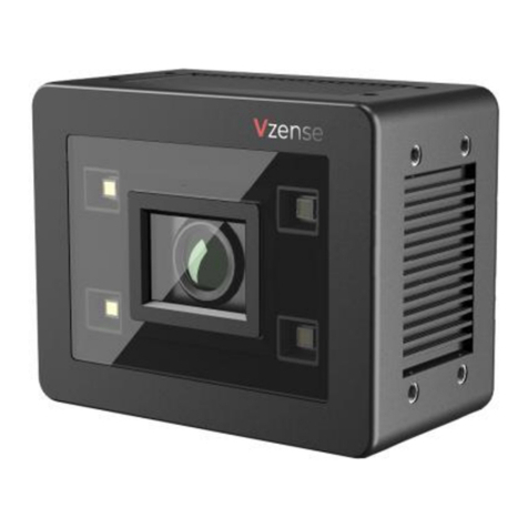
Vzense DCAM800 User manual

1
Vzense DCAM800 ToF Camera
User Manual

2
Table of Contents
1General Information............................................................................................ 4
1.1 Terms of Use............................................................................................ 4
2Precautions ........................................................................................................ 5
2.1 Safe Usage Instructions ........................................................................... 5
2.2 Power....................................................................................................... 5
2.3 Usage....................................................................................................... 5
2.4 Temperature............................................................................................. 6
3Specifications and Requirement......................................................................... 6
3.1 General Specifications.............................................................................. 6
3.2 Electrical Specifications............................................................................ 7
3.2.1 Recommended Operating Conditions............................................. 7
3.2.2 Power Consumption....................................................................... 7
3.2.3 Absolute Maximum Ratings............................................................ 8
3.3 Mechanical Specifications ........................................................................ 9
3.4 Working Condition Requirements........................................................... 10
3.4.1 Hardware Requirements............................................................... 10
3.4.2 Software Requirements................................................................ 10
3.4.3 Environmental Requirements ....................................................... 10
3.4.4 Coordinate of the Camera System ................................................11
4Interface with Host............................................................................................ 12
4.1 M16-10 MFP Connector ......................................................................... 12
4.2 M16-8 LAN Ethernet connector.............................................................. 15
4.3 LED indication........................................................................................ 16
5Principle of Time of Flight ................................................................................. 17
5.1 Scope of remote sensing technology...................................................... 17
5.1.1 Direct Time of Flight ..................................................................... 18
5.1.2 Range-gated Imaging ToF............................................................ 19
5.1.3 Continuous Waveform ToF........................................................... 19
5.1.4 Vzense ToF Principle.................................................................... 20
5.2 Noise Factors......................................................................................... 21
5.2.1 Ambient Light............................................................................... 21
5.2.2 Multipath Propagation .................................................................. 21
5.2.3 Reflectivity of the Target............................................................... 21
5.2.4 Scattering Effect........................................................................... 22
6Installation........................................................................................................ 22
6.1 Hardware Installation.............................................................................. 22
6.1.1 Ethernet Mode Installation............................................................ 22
6.1.2 POE Mode Installation.................................................................. 22
6.1.3 Standalone Mode Installation....................................................... 25
6.2 Software Installation............................................................................... 26
6.2.1 UTool............................................................................................ 26
6.2.2 Frameviewer ................................................................................ 26
3
6.2.3 SDK.............................................................................................. 26
6.3 Product State Machine........................................................................... 27
6.4 Software Command Set ......................................................................... 27
6.5 IPAddress Configuration........................................................................ 27
6.5.1 Direct Connection......................................................................... 28
6.5.2 DHCP Connection........................................................................ 28
7Features........................................................................................................... 29
7.1 Multiple Camera Synchronization........................................................... 29
7.2 Range Customization............................................................................. 29
7.3 Wide Dynamic Range............................................................................. 29
7.4 Data Filtering.......................................................................................... 30
7.5 IR Image................................................................................................. 31
7.6 Main screen............................................................................................ 32
7.6.1 Image area................................................................................... 32
7.6.2 Control area ................................................................................. 33
7.6.3 Information area........................................................................... 33
7.7 Connect devices..................................................................................... 33
7.8 2D view .................................................................................................. 34
7.8.1 Depth Image................................................................................. 34
7.8.2 IR Image ...................................................................................... 35
7.9 3D view .................................................................................................. 35
7.10 Save Image......................................................................................... 36
7.11 Camera Control...................................................................................... 37
7.11.1 Mode switch................................................................................. 37
7.11.2 Range change.............................................................................. 37
7.11.3 Exposure parameter modify ......................................................... 37
7.12 Filters Switch....................................................................................... 38
7.13 WDR................................................................................................... 38
8DCAM800 Accessories and Package ............................................................... 41
9Customization Service...................................................................................... 41
Appendix................................................................................................................. 41
ROHS Declaration............................................................................................ 41
Eye Safety Declaration..................................................................................... 41
Reliability Declaration....................................................................................... 41
Revision History...................................................................................................... 41

4
1 General Information
The purpose of this document is to familiarize the customer with the correct operation
of the Vzense ToF Camera. This document provides important information about the
camera’s features, hardware specification, safe use of the camera, and installation
procedures.
1.1 Terms of Use
Vzense offers a 1-year-warranty for this camera.
Warranty Information
Please do follow the following guidelines when using the Vzense camera:
Do not remove the product’s serial number label
Warranty must be void, if the label is damaged or removed and the serial number
can’t be read from the camera’s registers.
Do not open the camera housing
Do not open the housing. Touching any internal components may damage the camera.
Prevent any objects or substances from entering the camera housing.
Otherwise the camera may fail or damaged.
Avoid electromagnetic fields
Do not use the camera near strong electromagnetic fields. Prevent from electrostatic
charging.
Transport in original packaging
Transport and store the camera in its original packaging only. Do not discard the
packaging.
Clean with care
If you have to clean the housing of the camera, follow the guidelines in the notice as
below:
Use a soft, dry cloth that won’t generate static during cleaning;
To remove tough stains, use a soft cloth dampened with a small amount of
neutral detergent(Pure water); after that wipe dry;
Make sure no any residual detergent after cleaning, before reconnecting the
camera to power
Read the manual
Do read the manual carefully before using the camera.

5
2 Precautions
2.1 Safe Usage Instructions
DANGER
Electric Shock Risk
Non-standard and improper power supplies may result in fire and electric shock.
You must confirm the camera power supply used that meets the Safety Extra Low
Voltage(SELV) and Limited Power Supply (LPS) requirements.
CAUTION
Invisible Radiation
This camera uses laser to work, improper use may damage the eye. Lasers are
classified as risk group 1 (low risk) according to EN 60825 which means that the
product presents no risk related to exposure limits under normal usage conditions.
Eye safety is only guaranteed when the camera is used properly
2.2 Power
If you are supplying camera power via the camera’s 10-pin connector cable and the
voltage is higher than 24 VDC (±10 %), the camera may get damaged. If the voltage is
lower than 12V, the camera may not work as expected and you may not be able to
start the camera. Use a power supply with a minimum output current of 2 A at 24V
and 3A at 12V.
2.3 Usage
Don’t try to open the camera housing. Each camera has been calibrated at the factory
to achieve precise measurements. Touching internal components may damage the
camera and cause calibration data lost.
Incorrect plugging in and unplugging of the camera’s power cable can damage the
camera. To avoid switch-on surges damaging the camera, please plug in the power
cable into the camera’s 10-pin connector firstly before getting power supply.

6
Don’t try to change the position of the lens, may cause damage to the camera.
Do store the camera carefully when not in use, in original package the best.
2.4 Temperature
To avoid damaging the camera and to achieve best performance, please observe the
maximum and minimum housing temperatures in Section 3.1
3 Specifications and Requirement
3.1 General Specifications
Specification
Vzense DCAM800
Technology
ToF (Time-of-flight) Depth Camera
Depth Sensor Resolution and Frame
rate
640 x 480(VGA)@30FPS
Output Formats
Depth & IR Map (RAW12)
Depth Sensor Field of View
H-Horizontal, V-Vertical(degree)
H-58°
V-43.84°(customizable)
Use Range
0.2m~10m (customizable)
Accuracy
<1%
Power Consumption
Average Max. 10W(Ref)
Illumination
In-door 850nm/Out-door 940nm,4 x Vcsel
Dimension(L*W*H)
84mmx65mmx70mm
Weight
400g
Power Supply
DC 12V-24V / POE+ or above
Interface
1000M Ethernet, CAN-BUS
Digital I/O
(Exposure Control, Synchronization
etc.)
2in/2out
Enclosure Rating
IP65
Working/Storage Temperature
-20℃-50℃/-30℃-70℃

7
Software
C/C++ SDK
Operation System
Windows 7/8/10, Android, Linux
Cooling
Passive, no fan
Certification
FCC/CE/FDA
Eye safety
Class 1
3.2 Electrical Specifications
3.2.1 Recommended Operating Conditions
Parameter
Symbol
Conditions
Min
Typ.
Max
Units
Supply voltage on VDD
VDD
12
24
V
Digital I/O
(EXT_Trigger/
EXT_INPUT/)
Vin
Work
mode
3.3
24
V
Input
impedance *
560
Ω
Digital I/O
Exposure_timing/
EXT_OUTPUT)
Current
OD mode
40
mA
Voltage between pin
CANH and CANL
V(CANH-CANL
)
-24
24
V
Operating Temperature
Ta
-20
50
°C
Operating humidity
20
80
%
Storage humidity
20
80
%
Storage temperature
-30
70
°C
*: Please consider Vf range is about 1.3V
3.2.2 Power Consumption
Parameter
Conditions
Average
Max
Units
Current at
near mode
250mm-1200mm @30 frame
307
455
mA
Current at
far mode
800mm-4300mm @30frame
482
1011
mA
Current at
xfar mode
1200mm-6300mm@15frame
508
1986
mA
Note: 12V input voltage

8
3.2.3 Absolute Maximum Ratings
This is a stress rating only and functional operation of the devices at those or any
other conditions above those indicated in the operation listings of this specification is
not promised. Exposure to maximum rating conditions for extended periods may
affect device reliability
Parameter
Symbol
Conditions
Min
Typ.
Max
Units
Supply voltage on VDD
VDD
9
28
V
Digital I/O
(EXT_Trigger/
EXT_INPUT/
Exposure_timing/
EXT_OUTPUT)
Vio
Work mode
3.3
26
V
Voltage between pin
CANH and CANL
V(CANH-C
ANL)
-26
26
V
Operating Temperature
Ta
-20
50
°C

9
3.3 Mechanical Specifications
This drawing contains information about the dimensions and user mounting location of the
ToF Camera.
Fig. 1: ToF Camera Dimensions
Unit: mm

10
3.4 Working Condition Requirements
3.4.1 Hardware Requirements
Vzense ToF Camera
Power Adaptor (Included in package)
Customized Ethernet cable. Part number: VZENSE-LAN-8P-A (Included in
package)
Or
M16-10 Pin cable which provide power and interface with host. Part number:
VZENSE-MFP-10P-A (Not included in package)
Host device with 100M/1000M Ethernet
3.4.2 Software Requirements
Operating system
32-bit Windows 7/10
64-bit Windows 7/10 (recommended)
Linux (x86, x64)
Android 5.0 or above
Vzense ToF Driver
The Vzense ToF Driver software is available for Windows, Linux and Android
operating systems and includes the following:
SDK code
Sample code
Software user manual
3.4.3 Environmental Requirements
Temperature and Humidity
Housing temperature during operation:
Humidity during operation:
Storage temperature:
Storage humidity:
-20–50 °C
20–80 %, relative
-30–70 °C
20–80 %, relative
Heat Dissipation
Users can provide sufficient heat dissipation, like mounting the camera on a
substantial, thermally conductive component that can act as a heat sink. Or a fan can
be used to provide an air flow over the camera.

11
3.4.4 Coordinate of the Camera System
There are two coordinate system need to be understood, one is camera coordinate
system (CCS), one is world coordinate system (WCS).
CCS: CCS describe the two-dimensional data, the origin of coordinates is the optic
center.
WCS: WCS describe the three-dimensional information.
The CCS data can switch to the WCS data using the camera internal parameters.
Fig. 3: Origin of the Coordinate System
Meshlab and CloudCompare tools are recommended to analyze the point cloud data
saved by Vzense software or SDK method.
X
Y

12
4 Interface with Host
DCAM800 ToF Camera is equipped with two M16 connectors at the back of its
housing as shown in below figure.
For more information about pin assignments and connector types, see the following
sections.
Fig. 4: Camera Connectors
4.1 M16-10 MFP Connector
The M16-10 MFP (Multiple functional port) connector includes the two physical input
signals and two physical output signal, power supply source and CAN bus interface
can also be available in this interface.
The power adaptor in package can supply power to the camera via the M16-10 MFP
connector.
The optional cable VZENSE-MFP-10P-A can source all the signals in MFP connector
out, the user can do more applications.
The pin assignments and pin numbering for the receptacle are as shown in below
table.
The recommend detailed external signal connection ways please refer to section
3.4.and 3.4.
Pin
Designation
1
VCC
2
Ext_Trigger
3
GND
4
Ext_INPUT
5
CAN_H
6
Ext_OUTPUT
7
CAN_L
8
Exposure_timing
9
GND

13
10
External GND
Pin Description
Pin
Designation
Direction
Description
1
VCC
INPUT
12-24V power supply input
2
Ext_Trigger
INPUT
External trigger input(3.3V-24V)
3
GND
GND
System ground
4
Ext_INPUT
INPUT
Reserved for external input(3.3V-24V)
5
CAN_H
Positive signal of CAN BUS
6
Ext_OUTPUT
OUTPUT
Reserved for external output
7
CAN_L
Negative signal of CAN BUS
8
Exposure_timing
OUTPUT
Indicates the exposure timing
9
GND
GND
System ground
10
External GND
GND
Reference to external voltage
Hardware Trigger Function
Hardware trigger mode is available only when the camera works at slave mode, in
slave mode the camera will wait for the hardware trigger signal on Ext_Trigger.
The EXT_Trigger signal is opto-isolated, to driver the diodes, External input trigger
signal voltage should range 3.3V-24V, moreover the signal driving capacity should be
more than 60mA.
Camera input signal internal circuit
You can use input pin Ext_Trigger to send a hardware trigger signal to the camera.
The hardware trigger can be used to trigger the acquisition start. A hardware
debouncer circuit shall be considered on the EXT_Trigger line.
The polarity of the hardware trigger can be predefined by software command.
By default, the hardware trigger is low level activated, refer to below exposure timing:

14
T1
Start Exposure
EXT_Trigger
Camera Exposure
T1
Start Exposure
The requirement to T1 should be from 10us to 1ms, a hardware debouncer circuit
shall be considered on the EXT_Trigger line.
Reserved External INPUT Pin
An external INPUT pin, EXT_INPUT is reserved for advanced user, it can be
functional with software customization applications. NRE fee shall be charged if need
us to enable this feature according to customers requirement.
The EXT_INPUT pin is opto-isolated, to driver the diodes, External input trigger signal
voltage should range 3.3V-24V, moreover the signal driving capacity should be more
than 60mA.
Camera input signal internal circuit
Exposure_timing Pin Description
This pin is an output indicates the whole exposure period of the camera, polarity can
be predefined by software command. The internal circuit of this pin is open-drain, so
need a pull-up resistor circuit to enable the feature. The pull up voltage must follow
host system voltage level.

15
By default, the polarity is high level activated, which means a high-level signal
indicates the exposure period. Please refer to below figure:
Exposure Exposure
Exposure_timing Pin
Reserved External OUTPUT Pin
An external OUTPUT pin, Ext_OUTPUT is reserved for advanced user, it can be
functional with software customization applications. NRE fee shall be charged if need
us to enable this feature according to customers requirement.
The internal circuit of this pin is open-drain, so need a pull-up resistor circuit to enable
the feature. The pull up voltage must follow host system voltage level.
4.2 M16-8 LAN Ethernet connector
The M16-8 LAN Ethernet connector provides 1000M Ethernet access to the camera.
In addition, POE (Power over Ethernet) module is included in the camera. Users can
use POE as main power supply.
The cable VZENSE-LAN-8P-Ain the package shall be used if you want to get the data
via M16-8 Ethernet connector. The M16-8 LAN Ethernet connector is a waterproof
receptacle with the cable inserted.

16
8pin IO pin definition
Pin
Designation
Description
1
TD0+
Media Dependent
Interface[0], positive signal
of differential pair
2
TD0-
Media Dependent
Interface[0], negative signal
of differential pair
3
TD1+
Media Dependent
Interface[1], positive signal
of differential pair
4
TD2+
Media Dependent
Interface[2], positive signal
of differential pair
5
TD2-
Media Dependent
Interface[2], negative signal
of differential pair
6
TD1-
Media Dependent
Interface[1], negative signal
of differential pair
7
TD3+
Media Dependent
Interface[3], positive signal
of differential pair
8
TD3-
Media Dependent
Interface[3], negative signal
of differential pair
POE+ parameters description
CLASS
MINIMUM(W)
MAXIMUM Peak power(W)
IEEE802.3at
IEEE802.3bt
Class 4
12.5
25.5
4.3 LED indication
An LED locates in the back side of the camera, LED animation indicates the camera
status.
The LED animation table is shown as below:
Power off:

17
Broadcast:
Connected:
Upgrading:
5 Principle of Time of Flight
5.1 Scope of remote sensing technology
· Presence or proximity detection, where the absence or presence of an object in a
general area is the only information that is required (e.g., for security applications).
This is the simplest form of remote sensing;
· Speed measurement, where the exact position of an object does not need to be
known but where its accurate speed is required (e.g., for law enforcement
applications);
· Detection and ranging, where the position of an object relative to the sensor needs
to be precisely and accurately determined.
This document will concentrate on technologies capable of providing a detection and
ranging functionality, as it is the most complex of the three applications. From the
position information, presence and speed can be retrieved so technologies capable of
detection and ranging can be universally applied to all remote sensing applications.

18
5.1.1 Direct Time of Flight
In the direct time-of-flight measurement method, a discrete pulse is emitted and one
or several timers are used to measure the time difference between the emitted pulse
and the return echo, based on threshold detection. This time difference can be directly
converted to a distance, based on the following equation:

19
The difficulty in implementing the direct time-of-flight measurement method resides in
the time intervals to be measured. In order to resolve a distance to centimeter-level
accuracy, the required accuracy for the timers is 67 ps. Implemented in digital logic,
this would require a 15 GHz clock speed, which is obviously not practical. Therefore,
various time-to-digital conversion methods are typically used.
5.1.2 Range-gated Imaging ToF
Whereas direct time-of-flight relies on measurements made on the immediate value of
the received signal, range-gated imaging uses signal integration methods, typically
with CCD or CMOS imagers.
By measuring the energy received in successive integration intervals, it is possible to
extrapolate the distance between the sensor and the measured object, based on the
ratio of energy received in the different intervals.
The difficulty with range-gated imaging is that CCD and CMOS imagers have a limited
dynamic range; therefore, strong ambient light can easily cause saturation and impair
measurement. Furthermore, since neither the emitted and received pulses are perfect
rectangle pulses, nor is the sensor perfectly linear, compensation is required and
accuracy is ultimately limited.
5.1.3 Continuous Waveform ToF
In contrast to the previous two methods, phase difference measurement relies on a
modulated light source and evaluates the phase difference between the transmit

20
signal and the receive echo. This phase difference can be converted to a distance,
using the following formula:
Correlation methods are typically used to measure the phase difference of the receive
echo
respective to the transmit signal as well as recover the propagation delay and
therefore the
distance to the object to be measured.
Of course, a phase difference greater than 2 π is not resolvable; for instance, 3 π or 5
π will be measured as a π radian phase difference. Therefore, depending on the
chosen modulation frequency, an artefacting phenomenon will occur where far-away
objects will appear to be much closer than in reality.
5.1.4 Vzense ToF Principle
Vzense DCAM800 product principle is based on range-gated imaging ToF solution,
and the sensor inside is based on Panasonic CCD sensor MN34906.
Other manuals for DCAM800
1
Table of contents
Other Vzense Digital Camera manuals

Vzense
Vzense DCAM305 Installation instructions

Vzense
Vzense DS77 Series User manual

Vzense
Vzense DCAM710 User manual

Vzense
Vzense DCAM560C User manual

Vzense
Vzense DCAM500 User manual

Vzense
Vzense DCAM800 User manual

Vzense
Vzense DCAM550 User manual

Vzense
Vzense DS77C Lite User manual

Vzense
Vzense DS77 Series User manual

Vzense
Vzense DCAM550 User manual