WABCO SYSTEM SAVER HP MM1736 User manual

SYSTEM SAVER HP
AIR DRYER
MAINTENANCE MANUAL
MM1736

Table of Contents

3
Table of Contents
EN
Table of Contents
1 General Information ......................................................................................................................................... 4
2 Safety Information............................................................................................................................................ 6
3 Introduction ...................................................................................................................................................... 7
3.1 Overview .........................................................................7
3.2 AirDryerIdentication ...............................................................7
3.3 HowtheAirDryerWorks .............................................................7
3.3.1 Air Dryer Cycle .......................................................................................................................... 8
3.3.2 System Saver HP Air Dryer System .......................................................................................... 9
3.4 AirDryerComponents ..............................................................10
3.4.1 DryerIdenticationTag ........................................................................................................... 11
3.4.2 DescriptionofComponents..................................................................................................... 11
4 Component Removal and Installation.......................................................................................................... 14
4.1 ComponentReplacement ...........................................................14
4.1.1 Requirements.......................................................................................................................... 14
4.2 ComponentRemovalandInstallationProcedures ........................................16
4.2.1 DesiccantCartridge................................................................................................................. 16
4.2.2 Outlet Check Valve Assembly ................................................................................................. 18
4.2.3 Heater Assembly ..................................................................................................................... 19
4.2.4 TurboCut-OValveAssembly ................................................................................................ 20
4.2.5 Governor ................................................................................................................................. 20
4.2.6 PurgeValveAssembly ............................................................................................................ 21
4.2.7 Air Dryer Assembly.................................................................................................................. 21
5 Troubleshooting and Testing ........................................................................................................................ 23
5.1 Maintenance .....................................................................23
5.1.1 MaintenanceTips .................................................................................................................... 24
5.2 Troubleshooting ...................................................................24
5.2.1 Tests........................................................................................................................................ 27
5.2.2 Air Pressure Checks................................................................................................................ 28
6 Glossary.......................................................................................................................................................... 30
7 Application Information................................................................................................................................. 31
7.1 Recommendations.................................................................31
7.1.1 OperatingEnvironment ........................................................................................................... 31
7.1.2 DischargeLine ........................................................................................................................ 31
7.2 SystemSaverInstallationCriteria .....................................................32
Edition 2
10.2019
MM1736 1 (en)
This publication is not subject to any update service. Information contained in this
publication was in effect at the time the publication was approved for printing and is
subject to change without notice or liability. WABCO reserves the right to revise the
information presented or to discontinue the production of parts described at any time.

4
General Information General Information
EN 1 General Information
Symbols used in this document
DANGER
Descriptionofanimmediatesituationwhichwillresultinirreversibleinjuryordeathifthewarningis
ignored.
WARNING
Descriptionofapossiblesituationwhichmayresultinirreversibleinjuryordeathifthewarningis
ignored.
CAUTION
Descriptionofapossiblesituationwhichmayresultinirreversibleinjuryifthewarningisignored.
NOTICE
Descriptionofapossiblesituationwhichmayresultinmaterialdamageifthewarningisignored.
i
i
Importantinformation,notesand/ortips
www www
@
@ @@
Referencetoinformationontheinternet
1. Actionstep
- Actionstep
ÖConsequenceofanaction
List
• List
Note on the use of a tool/WABCO tool
How to Obtain Additional Maintenance, Service and Product Information
Ifyouhaveanyquestionsaboutthematerialcoveredinthispublication,orformoreinformationabout
theWABCOproductline,pleasecontactWABCOCustomerCareCenterat855-228-3203,byemailat
[email protected],orvisitourwebsite:www.wabco-na.com.

5
General Information
EN
WABCO Academy
www www
@
@ @@
https://www.wabco-academy.com/home/
WABCO online product catalog
www www
@
@ @@
http://inform.wabco-auto.com/
Your direct contact to WABCO
WABCO North America
WABCO USA LLC
1220 Pacic Drive
Auburn Hills, MI 48326
Customer Care Center: (855) 228-3203
www.wabco-na.com

6
Safety Information Introduction
EN 2 Safety Information
Provisions for a safe work environment
Onlytrainedandqualiedautotechniciansandautomechanicsmaycarryoutworkonthevehicle.
Readthispublicationcarefully.
Followallwarnings,noticesandinstructionstoavoidpersonalinjuryandpropertydamage.
Alwaysabidebythevehiclemanufacturer'sspecicationsandinstructions.
Observeallaccidentregulationsoftherespectivecompanyaswellasregionalandnational
regulations.
Theworkplaceshouldbedry,sucientlylitandventilated.
Usepersonalprotectiveequipmentifrequired(safetyshoes,protectivegoggles,respiratory
protectionandearprotectors).
ReadandobserveallDanger,WarningandCautionhazardalertmessagesinthispublication.They
provideinformationthatcanhelppreventseriouspersonalinjury,damagetocomponents,orboth.
WARNING
Topreventseriouseyeinjury,alwayswearsafeeyeprotectionwhenyouperformvehicle
maintenanceorservice.
WARNING
Parkthevehicleonalevelsurface.Blockthewheelstopreventthevehiclefrommoving.Supportthe
vehiclewithsafetystands.Donotworkunderavehiclesupportedonlybyjacks.Jackscansliporfall
over.Seriouspersonalinjuryanddamagetocomponentscanresult.
WARNING
Removeallairpressurefromtheairsystembeforeyoudisconnectanycomponent,includingthe
desiccantcartridge.Pressurizedaircancauseseriouspersonalinjury.

7
Introduction
EN
3 Introduction
3.1 Overview
MaintenanceManualMM1736containstroubleshootingstepsandserviceinformationfortheWABCO
SystemSaverHPsinglecartridgeairdryers.
IfyouhaveaWABCOSystemSaver(1200or1800)singlecartridgeairdryer,useMM34,WABCO
SystemSaverSeries(1200and1800)SingleCartridgeAirDryers.IfyouhaveaWABCOSystemSaver
Twinairdryer,useMM35,WABCOSystemSaverTwinAirDryer.Todownloadthesepublications,goto
wabco-na.com.
3.2 Air Dryer Identication
TheSystemSaverHPairdryerhasthegovernorintegratedintothebodyoftheairdryerandalsohasan
integratedpurgetank.Figure1.
Fig.1
4013285a
PURGE
TANK
GOVERNOR
3.3 How the Air Dryer Works
Duringsystempressurebuild-up,compressedairpassesintotheairdryerwheretheltersystemremoves
contaminantsandpassestheairintothedryingstage.
Moisture-ladenairpassesthroughthedesiccantbedintheairdryercartridgeandmoistureisretainedby
thedesiccant.Moisturethatcondensesoutalsocollectsinthebaseofthedryer.Whenthecompressor
unloads,thewaterisexpelledanddriedairowsbackthroughthedryer,dryingthedesiccantforthenext
cycle.

8
Introduction Introduction
EN 3.3.1 Air Dryer Cycle
AsinglecartridgeairdryercycleisillustratedinTableA.
Table A: Air Dryer Cycle
Cycle Stage Air Flow
Thegovernorturnsthecompressorloading
onwhensupplytankpressuredropsbelow
cut-inpressure,between105-115psi
(724-792kPa)dependingonthegovernor
settings.
4013565c
CONTROL
“WET” AIR
“DRY” AIR
COMPRESSOR
INTAKE LINE
Compressedairpassesintotheairdryerat
theinletport:
Moisture-ladenairandcontaminants
enterthedesiccant.
Moistureisretainedbydesiccant;
moisturealsocollectsinthebaseofthe
dryer.
Contaminantsareremovedasair
passesthroughthedesiccantbed.
4013286a
INLET
PORT 1
CARTRIDGE
OUTLET
PORT 2.1/2.2
Thegovernorunloadsthecompressor
whenthesystemreachescut-outlevel132
psi(910kPa)+/-3psi,dependingonthe
governorsettings.
4013566c
CONTROL
“WET” AIR
“DRY” AIR
COMPRESSOR
INTAKE LINE

9
Introduction
EN
Cycle Stage Air Flow
Whenthecompressorunloads,thepurge
valveopens.OntheSystemSaverHP:
Dryairowsfromtheintegratedpurge
tankbackthroughtheairdryer.Aircan
befeltandheardowingfromthepurge
valveforanextendedperiodoftime.
Drysystemairowsbackthroughthe
airdryertoregeneratedesiccant.
4013569a
PURGE PORT
3.2
CARTRIDGE
PURGE
TANK
3.3.2 System Saver HP Air Dryer System
Fig.2
4013288a
COMPRESSOR
DISCHARGE
LINE
COMPRESSOR
CONTROL
(PURGE)
PORT
DRYER
INLET PORT
COMPRESSOR
INTAKE LINE
SUPPLY
TANK
SYSTEM
RESERVOIRS
ONE-WAY
CHECK
VALV E
SYSTEM SAVER
IP AIR DRYER
UNLOADER
LINE
SUPPLY
LINE
PURGE VALV E
(EXHAUST)
ONE-WAY
CHECK
VALV E
10
Introduction Introduction
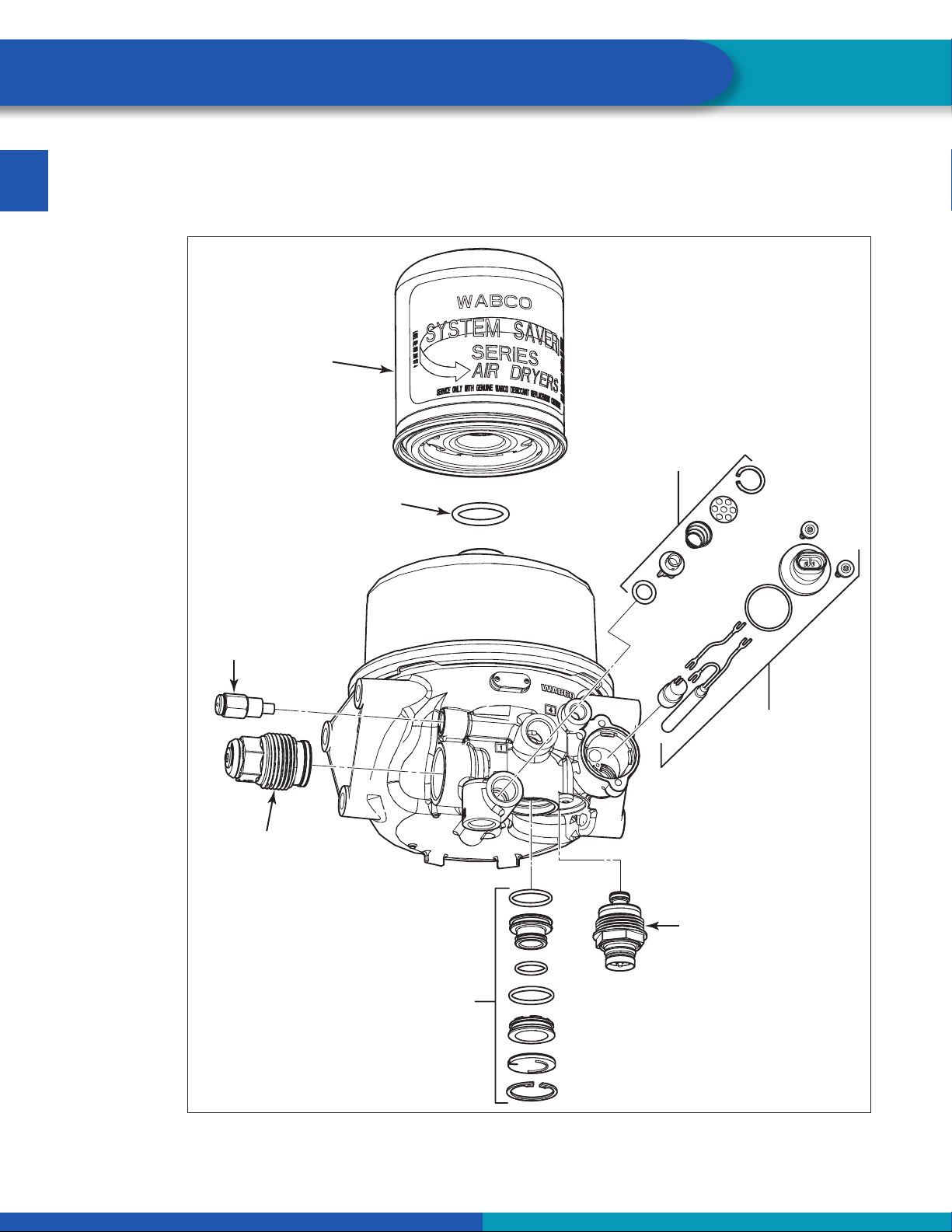
EN 3.4 Air Dryer Components
WABCOSystemSaverHPsinglecartridgeairdryerscontainreplaceablecomponentpartsshownin
Figure3.RefertoSection4forinstructionsforremovalofoldpartsandinstallationofnewparts.
Fig.3
4013289a
GOVERNOR
PORT 3.3
PRESSURE
RELIEF VALV E
PORT 3.1
DESICCANT
OR COALESCING
CARTRIDGE
O-RING
HEATER
ASSEMBLY
PORT 6
PURGE VALV E
ASSEMBLY
PORT 3.2
TURBO CUT-OFF
VALVE ASSEMBLY
PORT 3.4
OUTLET
CHECK VALV E
ASSEMBLY
PORT 2.1
Table of contents


