WABCO 446 300 400 0 User manual

Compact Tester 446 300 400 0 Bedienungsanleitung
Operating Instruction
GB
D


Compact Tester
446 300 400 0
Bedienungsanleitung
Operating Instruction
Ausgabe: Oktober 2001
October 2001 Edition
© Copyright WABCO 2005
Vehicle Control Systems
An American Standard Company
Änderungen bleiben vorbehalten
The right of amendment is reserved.
Version 10.01(de/en)
815 000 208 3

2
Inhaltsverzeichnis: Seite
WABCO Compact Tester 446 300 400 0 3
1. Anschließen des Testers 3
2. Fehler anzeigen (Taste <ERROR>) 3
3. Fehler löschen (Taste <CLEAR>) 4
4. System anzeigen (Taste <SYSTEM>) 4
5. Sonderfunktionen 5
5.1 Systemtaufe 5
(nicht bei Vario-C1, 446 105 001 0 und 446 105 009 0)
5.2 Funktionstest 5
(Inbetriebnahmezyklus) - nur VCS -
5.2.1 Inbetriebnahme - ohne Bremsdruck - 6
5.2.2 Inbetriebnahme - mit Bremsdruck - 6
5.3 Kilometerzähler 7
5.4 Anzeige Geschwindigkeitsschwelle 8
5.5 Serviceintervall zurücksetzen 8
6. Zusammenfassung 9
Table of Contents Page
WABCO Compact Tester 446 300 400 0 11
1. Connection for diagnosis 11
2. Fault display ( <ERROR> key ) 11
3. Clear fault ( <CLEAR> key ) 12
4. Display system ( <SYSTEM> key ) 12
5. Special functions 13
5.1 System initialisation 13
(not on Vario-C1, 446 105 001 0 and 446 105 009 0)
5.2 Function test 13
(System test - VCS only - )
5.2.1 System check - without brake pressure - 14
5.2.2 System check - with brake pressure - 14
5.3 Odometer 15
5.4. Display speed threshold 16
5.5. Reset Service Interval 16
6. Summary 17
GB
D

3
WABCO Compact Tester
446 300 400 0
WABCO hat ein neues, preiswertes und
– hinsichtlich Bedienung – einfaches
Diagnosegerät entwickelt: den Com-
pact Tester.
Mit diesem Tester ist es möglich, An-
hänger-ABS-Systeme der Typen Vario
C und Vario Compact bis hin zur Inbe-
triebnahme zu prüfen.
1. Anschließen des Testers
– Neunpoligen Stecker des WABCO-
Diagnosekabels (z. B. 446 300 401
0) in die zugehörige Buchse des
Compact Testers stecken.
– Stecker an der Fahrzeugseite des
Diagnosekabels in die Diagnose-
buchse am Fahrzeug stecken (zum
Stecken in die ECU ist zusätzlich das
Diagnosekabel 449 612 … 0 erfor-
derlich, für Vario C Adapter 446 300
318 0).
– Zündung einschalten.
Die Anzeige des Testers leuchtet sofort
auf (Anzeige: 888). Nach ca. 1 Sekun-
de versucht der Tester die Diagnose-
verbindung mit der ECU herzustellen.
Gleichzeitig beginnt die Anzeige zu blin-
ken.
Ist die Verbindung erfolgreich herge-
stellt, wird das erkannte System ange-
zeigt:
– UCS = VCS-ECU oder
– UC1 = Vario-C1 (446 105 001 0 und
446 105 009 0) oder
– UC2 = Vario-C2 (446 105 023 0, 446
105 03 . 0 und 446 105 05 . 0)
Die nachfolgend aufgeführten Funktio-
nen können durch entsprechenden Ta-
stendruck gestartet werden.
2. Fehler anzeigen
(Taste <ERROR>)
Nach Betätigung der Taste <ERROR>
werden die gespeicherten Fehler ange-
zeigt. Der zuletzt aufgetretene Fehler
erscheint als erster (Last in - first out).
Dieser Fehler wird immer in folgender
Form dargestellt:
1. Stelle 2. Stelle 3. Stelle
Fehlerpfad Fehlertyp Fehleranzahl
Auf der Vorderseite des Compact
Testers werden die Fehler mit Hilfe von
Pictogrammen aufgeschlüsselt. Zusam-
mengehörige Fehlergruppen sind durch
einen waagerechten Strich gekenn-
zeichnet (Sensor, Modulator oder
ECU). Innerhalb einer Gruppe können
verschiedene Kombinationen von Feh-
lerpfad und Fehlertyp auftreten.
D

4
Beispiele:
Anzeige: Erklärung:
4 7 1 Geschwindigkeitssensor Rad D, Luftspalt zu groß,
1 X aufgetreten
4 b 2 Geschwindigkeitssensor Rad D, Reifendruck, 2 X aufgetreten
A 6 1 Modulator B, Masseschluß, 1 X aufgetreten
d 5 9 Retarder, Kabelbruch, 9 X aufgetreten
0Kein Fehler gespeichert
D
Durch weiteres Betätigen der Taste
<ERROR> werden die nächsten Fehler
zur Anzeige gebracht. Wenn der letzte
Fehler erreicht wurde, erscheint wieder
der erkannte Elektroniktyp (s. Punkt 1,
z. B. UCS).
Für die Fehleranzeige bei Elektroniken
des Typs Vario-C ist auf der Rückseite
des Testers eine weitere Folie mit zu-
sätzlichen erklärenden Pictogrammen
angebracht.
3. Fehler löschen
(Taste <CLEAR>)
Durch Betätigung der Taste <CLEAR>
wird der gesamte Fehlerspeicher der
ECU gelöscht. Voraussetzung : kein ak-
tueller Fehler vorhanden! Anschließend
wird wieder der erkannte ECU-Typ an-
gezeigt (s. Punkt 1).
4. System anzeigen
(Taste <SYSTEM>)
Durch Betätigung der Taste
<SYSTEM>
kann das von der ECU erkannte System
angezeigt werden. Das System wird in
folgender Form dargestellt:
1. Stelle 2. Stelle 3. Stelle
Anzahl - oder r/U Anzahl
Sensoren für Retarder Modulatoren
Beispiel:
4 - 2 = System 4S / 2M = 4 Senso-
ren / 2 Modulatoren
4 r 3 = System 4S / 3M = mit Retar-
der
4 U 2 = System 4S / 2M = mit ISS
(Integrierter geschwindig-
keitsabhängiger Schalter).

5
5. Sonderfunktionen
Die Sonderfunktionen können nur durch
Drücken besonderer Tastenkombinatio-
nen gestartet werden. Dadurch wird ein
versehentliches Auslösen der Funktio-
nen verhindert.
5.1 Systemtaufe
(nicht bei Vario-C1, 446 105 001 0
und 446 105 009 0)
Die Systemtaufe, das automatische Er-
kennen und Speichern der Systemkon-
figuration, wird aktiviert durch:
–Taste<SYSTEM> drücken und los-
lassen
– System (z. B. 4 - 2 ) wird angezeigt
–Taste<SYSTEM> für 2 s festhalten
Nach Ablauf der 2 Sekunden beginnt
die Anzeige mit dem erkannten System
zu blinken. Die Taufe wird automatisch
durchgeführt, der Fehlerspeicher wird
gelöscht und anschließend wird das ge-
taufte System angezeigt. Damit ist
gleichzeitig eine Überprüfung der Sy-
stemtaufe möglich.
Die Systemtaufe bei der Vario C2 Ge-
neration sieht folgenden Ablauf vor:
–Taste<CLEAR> drücken und loslas-
sen
–Taste<SYSTEM> drücken und los-
lassen
– System (z. B. 4 - 2) wird angezeigt
–Taste<SYSTEM> für 2 s festhalten.
Der Diagnosemodus wird verlassen
und anschließend für ca. 2 Sekunden
das erkannte System angezeigt. Da-
nach muß ca. 40 Sekunden lang gewar-
tet werden. Diese Zeit wird durch einen
„Count down“ überbrückt. Anschließend
wird der Diagnosemodus wiederherge-
stellt und das neu erkannte System an-
gezeigt.
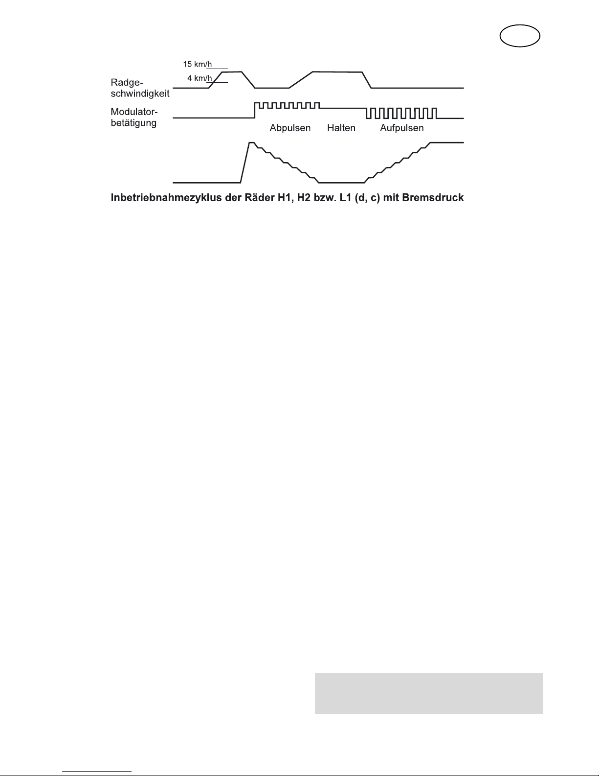
5.2 Funktionstest (Inbetriebnahme-
zyklus - nur VCS - )
Nach der Erstinstallation oder Änderun-
gen an der ABS Anlage muß die richtige
pneumatische und elektrische Zuord-
nung überprüft werden.
Voraussetzung:
– fehlerfreies System
– vom Rollenprüfstand oder von Hand
gedrehtes Rad (V = 1,8 – 15 km/h).
Der Funktionstest wird folgendermaßen
aktiviert:
–Taste<SYSTEM> drücken und los-
lassen
– System (z. B. 4 - 2) wird angezeigt
–Taste <CLEAR> für 2 Sekunden
festhalten.
Nach Ablauf von 2 Sekunden erscheint
die Anzeige: SYS. Bei älteren Elektroni-
ken blinkt die Anzeige mehrere Sekun-
den lang. Erst wenn die Anzeige SYS
nicht mehr blinkt, kann mit dem Funkti-
onstest fortgefahren werden.
D

6
5.2.1 Inbetriebnahme
-ohne Bremsdruck -
Jetzt kann ein einzelnes Rad gedreht
werden. Nach Stillstand des zuvor ge-
drehten Rades wird der zugehörige Mo-
dulator angesteuert.
Die Zuordnung Sensor / Modulator wird
überprüft, indem während der Modula-
torbetätigung der richtige Modulator
durch Hören oder Anfassen ermittelt
werden. Der Funktionstest wird durch
Betätigung einer beliebigen Taste ab-
gebrochen.
Nach erfolgreich durchgeführtem Funk-
tionstest ist das System betriebsbereit.
D
5.2.2 Inbetriebnahme
-mit Bremsdruck -

7
D
Um die komplette elektrische/pneumati-
sche Zuordnung Sensor/ Bremszylinder
zu überprüfen, ist eine Druckluftversor-
gung notwendig.
Voraussetzung:
– Bremszylinder drucklos
– sonst wie Inbetriebnahme
- ohne Bremsdruck - s. 5.2.1
Prüfung:
– Rad drehen (1,8 < V < 15 km/h)
– Bremsanlage einbremsen
– Magnetbetätigung beginnt, gedreh-
tes Rad wird entlüftet und ist jetzt 3s
drehbar
– kann das Rad nach Entlüftung nicht
gedreht werden, ist die Zuordnung
Sensor / Zylinder falsch (gilt für Rä-
der f, e bzw. Z1, Z2, L2)
– zur besseren Unterscheidung wer-
den Räder H1, H2, und L nicht sofort
entlüftet sondern abgepulst. (Über-
prüfung ohne Hilfsmittel)
Meistens regelt ein Modulator mehrere
Räder. Um aber bei sensierten Rädern
eines Modulators zwischen H- (c, d) und
Z- (e, f) Rädern unterscheiden zu kön-
nen (z. B. Liftachsen), sind die Entlüf-
tungszyklen unterschiedlich. Die H- (c,
d) Achse wird 8x gepulst, die Z- (e, f)
Achse wird voll entlüftet. Bei der L- Ach-
se werden L1 (f) und L2 (e) unterschie-
den. L1 wird abgepulst und L2 voll
entlüftet.
Ende der Inbetriebnahme: Erneutes
Starten ist durch Reset (Zündung Aus /
Ein) möglich.
5.3 Kilometerzähler
Mit dem Compact-Tester kann der Ge-
samtkilometerstand ausgelesen wer-
den.
Die erforderlichen Reifenparameter
(Reifendurchmesser, Polrad) sind bei
der Erstausrüstung werkseitig einge-
stellt. Eine Veränderung dieser Para-
meter ist mit dem Tester nicht möglich,
sondern kann nur mit dem WABCO Dia-
gnostic Controller 446 300 320 0 durch-
geführt werden.
Die Anzeige des Kilometerstandes wird
durch folgende Tastenkombination
ausgelöst:
Gleichzeitige Betätigung der Tasten
CLEAR und SYSTEM.

8
D
Der Kilometerstand wird 6-stellig ange-
zeigt. Wegen der 3-stelligen Anzeige er-
folgt die Ausgabe in 2 Blöcken, von
oben beginnend.
Durch Betätigung einer beliebigen Ta-
ste, werden die jeweils nächsten 3 Stel-
len angezeigt. Als Startsignal für die
Anzeige des Kilometerstandes werden
3 waagerechte Striche ( - - - ) ange-
zeigt.
Wurden alle Stellen nacheinander ab-
gefragt, erscheint automatisch <UCS>.
Beispiel: 149 322 = 149322 gefahrene
Gesamtkilometer.
5.4 Anzeige Geschwindigkeits-
schwelle
Die VCS Elektronik wird zukünftig auch
mit einem integrierten geschwindig-
keitsabhängigem Schalter (ISS) ausge-
liefert. Damit können z. B. Lenkachsen
gesperrt bzw. Liftachsen angesteuert
werden.
Die Geschwindigkeitsschwelle können
Sie nur mit dem Diagnosecontroller
(zwischen 4 … 120 km/h) parametrie-
ren. Mit dem Compact Tester ist ein
Auslesen dieser parametrierten Ge-
schwindigkeit möglich.
Durch die Tastenkombination
ERROR + CLEAR wird diese Ge-
schwindigkeit in km /h angezeigt.
5.5 Serviceintervall zurückset-
zen
Desweiteren werden die zukünftigen
VCS Elektroniken mit einem elektroni-
schen Notizbuch ausgerüstet. Hier kann
ebenfalls mit dem Diagnosecontroller
ein Servicesignal gesetzt werden (z. B.
Gestängesteller abschmieren).
Wenn das Signal gesetzt ist, erscheint
nach einer definierten KM-Schwelle
(Werkseinstellung alle 30.000 km) ein
Warnsignal im Fahrerhaus (8-maliges
Schnellblinken der SILA). Das Zurück-
setzen dieses Signals ist ebenfalls mit
dem Compact Tester möglich.
Durch die Tastenkombination
ERROR + SYSTEM wird das
Servicesignal zurückgesetzt.

9
6. Zusammenfassung
Taste Anzeige
(Beispiele)
Funktion Bemerkungen
ERROR 471 Fehleranzeige Anzeige: Fehlerpfad, Fehlertyp
und Fehlerhäufigkeit
CLEAR Clr Löschen des
Fehlerspeichers
Vorr.: Kein aktueller Fehler
vorhanden
SYSTEM (4 - 2) Systemanzeige z. B.: 4S / 2M
4 r 2 4S / 2M mit Retarder
4 U 2 4S / 2M mit ISS
Sonderfunktionen: siehe Reihenfolge (Reihenfolge beachten!)
1. System (2 - 2) Taste drücken + loslassen
2. System 2-2 (blinkt) Systemtaufe Taste 2 s festhalten. Anzeige:
erkanntes System
1. System (2 - 2) Taste drücken + loslassen
2. Clear SyS Funktionstest Taste 2 s halten. Inbetrieb-
nahmezyklus starten
Clear +
System
( - - - ) Gesamt -
Kilometer
Ausgabe der gefahrenen
Kilometer in dreistelliger
Form (insges. 6 Stellen)
beliebig 456 789 (km)
beliebig VCS
ERROR +
CLEAR
OFF oder
060 (KM)
Geschwindig-
keitsschwelle
Anzeige der Geschwindig-
keitsschwelle in km/h
ERROR +
SYSTEM
- - -
(kurz blinkend)
Serviceintervall
zurücksetzen
D

10
GB
WABCO Compact Tester
446 300 400 0
WABCO have developed a new, eco-
nomical and simple ABS diagnostic tool
for trained works personnel, the Com-
pact Tester.
With this tester it is possible for the first
time to test the trailer electronics of
types Vario C and VCS (Vario Compact)
without documentation and carry out a
proper system check. This is made pos-
sible by the logical arrangement of
icons.
1. Connection for diagnosis
– Insert the nine pin plug of the
WABCO diagnostic cable (e.g. 446
300 401 0) into the appropriate
socket in the Compact Tester.
– Insert the plug on the diagnostic
cable into the diagnostic socket on
the vehicle (to plug into the ECU
diagnostic cable 449 612 0 is also
needed, for Vario C Adapter 446 300
318 0).
– Switch on ignition.
The display on the tester lights up im-
mediately (display: 888). After about 1
second the tester tries to make the diag-
nostic connection with the ECU. At the
same time the display starts to flash. If
the connection is correctly made the
type of electronic system will be dis-
played:
– UCS = VCS-ECU or
– UC1= Vario-C1 (446 105 001 0 and
446 105 009 0) or
– UC2 = Vario-C2 (446 105 023 0, 446
105 03- 0 or 446 105 05- 0)
The following functions can be started
by pressing the appropriate key.
2. Fault display
(<ERROR> key)
After the „ERROR“ key has been
pressed the first fault stored in the ECU
will be displayed. The last fault to occur
will be the first to be displayed (last in -
first out). This fault is always shown in
the following form:
1st place 2nd place 3rd place
Component Fault type Numberof
Faults Fault
On the front of the Compact Tester the
faults are coded by icons. Related
groups of faults are marked by a hori-
zontal line (sensor, modulator or ECU).
Different combinations of component
faults and types can occur within a sin-
gle group.

11
GB
Examples:
Display: Explanation:
4 7 1 Speed sensor wheel D, air gap too big, occurred once
4 b 2 Speed sensor wheel D, tyre pressure, occurred twice
A 6 1 Modulator B, earth leakage, occurred once.
d 5 9 Retarder, cable break, occurred 9 times.
0No faults in memory.
By pressing the „ERROR“ key again
the next fault can be displayed. When
the last stored fault is reached, the ac-
knowledged electronic system comes
up again (see point l, e.g. UCS).
To display the faults in type Vario-C
electronic systems there is another pan-
el with explanatory icons on the back of
the tester.
3. Clear fault
(<CLEAR> key)
When the <CLEAR> key is pressed the
whole fault memory of the ECU is
cleared. Requirement: no current faults
present! Then the ECU type is dis-
played again (see point 1).
4. Display system
(<SYSTEM> key)
When the <SYSTEM> key is pressed
the system acknowledged by the ECU
can be displayed. The system is repre-
sented in the following form:
1st place 2nd place 3rd place
Number - or r/U Number of
of sensors for Retarder modulators
Example:
4 - 2 = system 4S/2M = 4 sensors
/ 2 modulators
4 r 3 = system 4S/3M = with retarder
4 U 2= system 4S/2M = with ISS
(Internal Speed Switch)

12
GB
5. Special functions
The special functions cannot be started
by simply pressing the keys. This is to
prevent the accidental activation of the
functions. These special functions are
not available for every type of electronic
system.
5.1. System Initialisation
(not on Vario-C1, 446 105 001 0
and 446 105 009 0)
The system initialisation is activated by
pressing the following keys:
– Press and release <SYSTEM> key
– System (e.g. 4 - 2) is displayed
– Hold down <SYSTEM> key for 2
secs.
After two seconds the display starts to
flash with the acknowledged system. It
is automatically set, the fault memory is
cleared and then the set system is dis-
played. This gives a simultaneous sys-
tem set test.
If the system is to be set on a Vario C2
ECU, the sequence is as follows (like
VCS):
– Press and release <CLEAR> key
– Press and release <SYSTEM> key
– System (e.g. 4 - 2) is displayed
– Hold down <SYSTEM> key for 2
secs.
The diagnostic mode is left and then for
about 2 secs the acknowledged system
is displayed. Then it is necessary to wait
for about 40 seconds. This time is
counted down. Then the diagnostic
mode is resumed and the newly ac-
knowledged system is displayed.
5.2. Function test
(System Test - VCS only - )
The correct pneumatic and electric con-
nections have to be checked after the
first installation or changes of the ABS
system.
Condition: faultless system
The function test is activated by press-
ing the following keys:
– Press and release <SYSTEM> key
– System (e.g. 4 - 2) is displayed
– Hold down <CLEAR> key for 2 secs.
After 2 seconds the function test is dis-
played by: SYS. When you have older
electronic units the display blinks rapidly
for some seconds. Only when the blink-
ing of the signal SYS has stopped you
can go ahead with the functional test.
Then a single wheel can be turned.
When the rotated wheel is at a standstill
the appropriate modulator is triggered.
This can be repeated as often as you
wish. After finalisation of the function
test the system is ready to work.

13
GB
5.2.1. System check
- without brake pressure -
After the installation of or any alteration
to the ABS system the correct pneumat-
ic and electrical allocation must be
checked.
Requirement:
– Fault-free system
– Wheel turned from rolling road or by
hand (V= 1,8-15 km/h).
Testing:
– Start function test as described
above
– Turn one wheel then stop it.
– The ECU activates the appropriate
modulator as soon as the wheel is
stationary.
If you only wish to test the electrical sen-
sor/modulator set-up, while the modula-
tor is in operation the correct modulator
can be ascertained by listening or con-
tact.

14
GB
5.2.2 System check
- with brake pressure -
In order to test the complete electrical/
pneumatic sensor/brake chamber set-
up, a compressed air supply is needed.
Requirement:
– no pressure in brake chamber
– otherwise as for system check
without brake pressure, see 5.2.1
Testing:
– Turn wheel (1,8 < V < 15 km/h)
– Apply Brake
– Solenoid starts to activate, the
rotated wheel is exhausted and can
now be turned for 3 secs.
– If the wheel will not turn after it has
been exhausted, the sensor/chamber
are incorrectly matched (applies to
wheels f, e and A and Z1, Z1, L2)
– To achieve a better differentiation,
wheels H1, H2 and L are not
exhausted immediately, but pulsed
down (testing without auxiliary
equipment).
In most instances one modulator con-
trols more than one wheel. In order to
differentiate between the wheel of one
modulator H- (c, d) and Z (e, f) (e.g. lift-
ing axles), the exhaust cycles are differ-
ent. The H- (c, d) axle is pulsed 8 x, the
Z- (e, f) axle is fully exhausted. On the L
axle L1 (f) and L2 (e) differ. L1 is pulsed
down and L2 is fully exhausted.
End of system check: to start again
please push reset (ignition off / on).

15
GB
5.3. Odometer
With the Compact Tester the total
number of km can be read out. The nec-
essary tyre parameters (tyre diameter,
polewheel tooth no) are already set in
the memory of the ECU. It is not possi-
ble to change these parameters with the
tester, it can only be done with the WA-
BCO Diagnostic Controller 446 300 320
0 or PC-Diagnostics.
The number of km can be displayed
with the following key combination:
Simultaneously press the
“CLEAR” and “SYSTEM” keys.
The km covered are displayed to 6 plac-
es in km. The digits are displayed 3 at a
time, starting with the 3 highest figures.
By pressing any key the next 3 places
can be displayed (total 2x).
The starting signal for the km display is
3 horizontal lines ( - - - ), followed by the
3 highest figures. If all figures one after
another have been asked for “UCS”
comes up automatically.
Example: 149 322 = 149322 total km
travelled.
5.4. Display speed threshold
Some VCS electronic units are supplied
with an Integrated Speed dependent
Switch (ISS). This switch can be used,
for example, to lock a steering axle or
control a lift axle.
The setting of the speed threshold pa-
rameter can only be set using the diag-
nostic controller (between 4 - 120 km/h).
To display the speed threshold
value (in km/h) use key combina-
tion ERROR + CLEAR.
5.5. Reset Service Interval
An additional feature in future VCS elec-
tronic units is a service interval counter
(in km).
When this service interval is exceeded
the driver is informed by the rapid blink-
ing (8 flashes) of the dash warming
lamp after the ignition is switched on.
The factory setting for this counter is
30,000 km.
To reset the service signal use
key combination ERROR +
SYSTEM.

16
GB
6. Summary
Key Display
(Example)
Function Comments
ERROR 471 Fault display Display component, type
and frequency
CLEAR Clr Clear
memory
Requirement:
no fault present
SYSTEM (4 - 2) System display e. g. 4S / 2M
4 r 2 4S / 2M with retarder
4 U 2 4S / 2M with ISS
Special functions: see sequence
1. System (2 - 2) Press + release key
2. System 2-2 (flash) System set Hold key 2 secs.
See: acknowledged system
1. System (2 - 2) Press + release key
2. Clear SyS Function test Hold key 2 secs.
to start system check
Clear +
System
( - - - ) Total km See total km
× 3 digits (total 6)
Any 456 789 (km)
Any 456 789 (km)
Any VCS
ERROR +
CLEAR
OFF or
060 (KM)
Speed
threshold
Display of speed threshold
in km/h
ERROR +
SYSTEM
- - -
(rapid blinking)
Reset Service
Interval

17
Aufkleber auf der Rückseite
Sticker on Back Panel
D
GB

18
WABCO, the vehicle control sys-
tems business of American Stand-
ard Companies, is one of the
world's leading producers of elec-
tronic braking, stability, suspen-
sion and transmission control
systems for heavy duty commer-
cial vehicles. WABCO products
are also increasingly used in luxu-
ry cars and sport utility vehicles
(SUVs). Customers include the
world's leading commercial truck,
trailer, bus and passenger car
manufacturers. Founded in the US
136 years ago as Westinghouse
Air Brake Company, WABCO was
acquired by American Standard in
1968. Headquartered in Brussels,
Belgium, the business today em-
ploys nearly 6700 people in 30 of-
fice and production facilities
worldwide. In 2004, WABCO con-
tributed US$1.72 billion to Ameri-
can Standard's total sales of more
than US$9.50 billion.
Website: www.wabco-auto.com
© 2005 American Standard All rights reserved 815 000 208 3/04.2005
Vehicle Control Systems
An American Standard Company
Table of contents
Languages:
Other WABCO Measuring Instrument manuals
Popular Measuring Instrument manuals by other brands

dtec
dtec CONTROL V7E Operation manual

DENT Instruments
DENT Instruments powerscout 3037 Operator's guide

Guildline
Guildline 6675A Technical manual

Ellisys
Ellisys USB Explorer 350 user manual

Hanna Instruments
Hanna Instruments HI 7635 instruction manual

Pro-Ject Audio Systems
Pro-Ject Audio Systems Measure it E manual