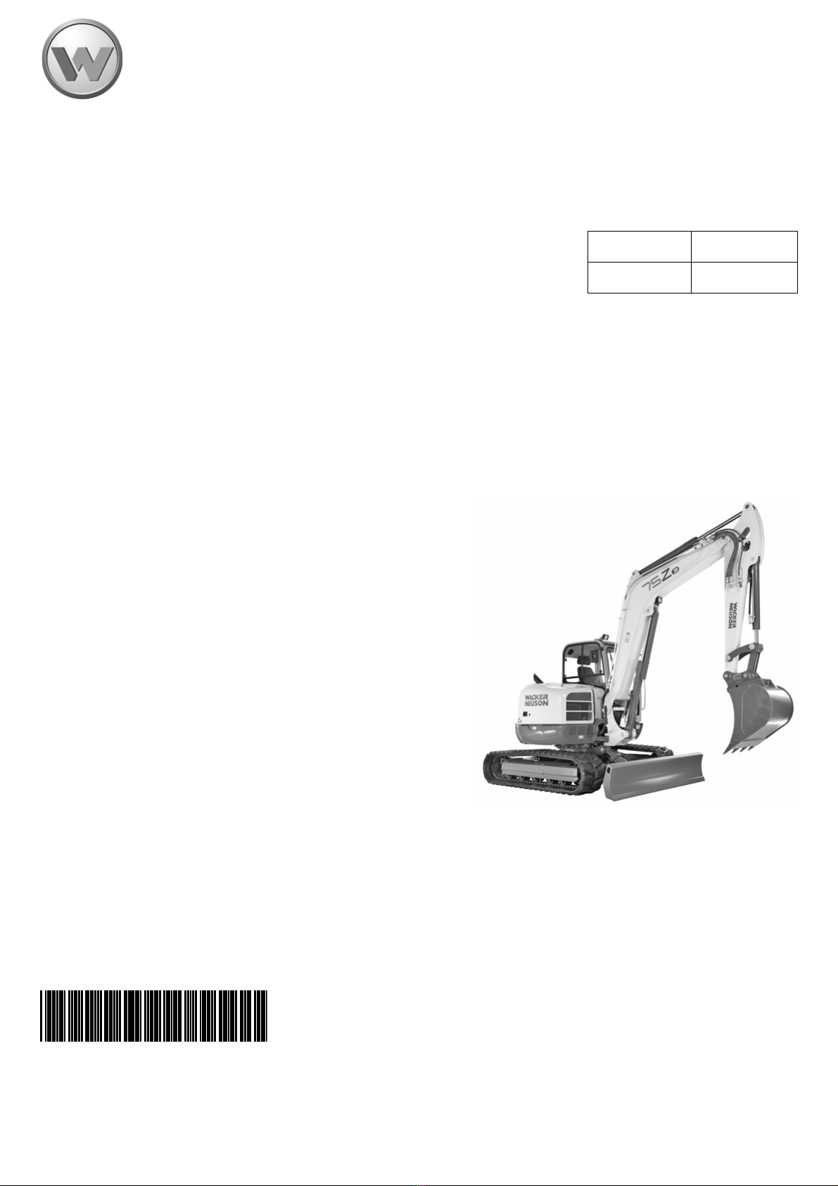
OM 75Z3/8003 US – Edition 4.0 * 7003b110.fm 1-1
Introduction
1 Introduction
1.1 Important Operator Information
Store the Operator's Manual in the storage compartment behind the seat.
This Operator's Manual contains important information on how to work safely, correctly
and economically with the machine. This Operator's Manual provides information and
instructionsforalloperatorsregardless of experience.Ithelps to avoid risky situations and
reduce repair costs and downtimes. Furthermore, the reliability and the service life of the
machine will be increased by following the instructions in the Operator's Manual. This is
why the Operator's Manual must always be kept at hand in the machine.
Your own safety, as well as the safety of others, depends to a great extent on how the
machine is moved and operated. Thoroughly read and understand the information in this
Operator's Manual before operating the machine for the first time. This Operator's Manual
willhelp tofamiliarize yourself moreeasily with themachine, thereby enabling youtouse it
more safely and efficiently.
Before operating this machine for the first time, carefully read the section "Safety Instruc-
tions" to learn how to operate the machine safely.
Careful and prudent working is the best way to avoid accidents.
• Instructions are provided for bucket attachments. No instructions are providedfor other
attachments. Refer to the specific attachment operator's manual for safe operation.
• Wacker Neuson reserves the right to make product improvement changes during the
course of series production of this machine.
• Modifying the manufacturer specification and configuration of this machine, or using
unapproved attachments, can cause personal hazards and damage the machine.
Contact your Wacker Neuson dealer for additional information and clarification
regarding modifications.
Operationalsafety and readiness of the machine do notonly depend on your skill,but also
on maintenance and servicing of the machine. This is why regular maintenance and ser-
vicework isabsolutelynecessary. Extensive maintenanceandrepairwork mustalwaysbe
performed by an expert with appropriate training. Use only original spare parts for repairs.
This ensures operational safety and readiness of your machine, and maintains its value.
• Special equipment and superstructures are not described in this Operator's Manual.
• We reserve the right to improve the technical standard of our machines without
adapting the Operator's Manual.
• Modifying Wacker Neuson products and fitting them with additional equipment and
attachments not included in our delivery program requires Wacker Neuson's written
authorization, otherwise warranty and product liability for possible damage caused by
these modifications shall not be applicable.
• Subject to modifications and printing errors.
Your Wacker Neuson dealer will be pleased to answerany furtherquestions regarding the
machine or the Operator's Manual.