WADE Antenna, Inc. PB-81 User manual
Other WADE Antenna, Inc. Antenna manuals

WADE Antenna, Inc.
WADE Antenna, Inc. Taco Antenna D4000 Series User manual

WADE Antenna, Inc.
WADE Antenna, Inc. J-283X User manual

WADE Antenna, Inc.
WADE Antenna, Inc. J55-2 User manual

WADE Antenna, Inc.
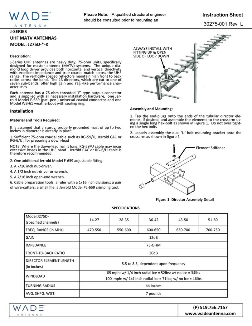
WADE Antenna, Inc. J275D-*-K User manual

WADE Antenna, Inc.
WADE Antenna, Inc. D-1338BB User manual

WADE Antenna, Inc.
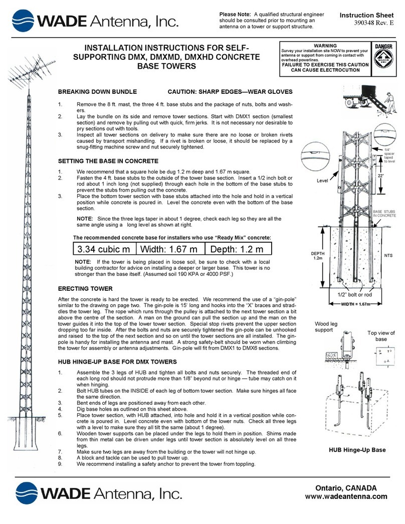
WADE Antenna, Inc. DMX, DMXMD, DMXHD User manual
Popular Antenna manuals by other brands

Alfa Network
Alfa Network APA-L01 Specifications

Naval
Naval PR-422CA Operation manual

Feig Electronic
Feig Electronic ID ISC.ANTH200/200 Series manual

TERK Technologies
TERK Technologies TV44 owner's manual

Directive Systems & Engineering
Directive Systems & Engineering DSE2324LYRMK quick start guide

HP
HP J8999A instructions

CommScope
CommScope CMAX-OMFX-43M-I53 Installation instruction

Ramsey Electronics
Ramsey Electronics DAP25 Kit assembly and instruction manual

COBHAM
COBHAM SAILOR 800 VSAT Replacement procedure

Trango Systems
Trango Systems AD900-9 Specification sheet

Steren
Steren ANT-100 user manual

IWCS
IWCS iriBelt II Quick start user guide


