Wagner & Co EURO C22 User manual

INSTALLATION INSTRUCTIONS Wagner & C
o
EURO C20/C22 On-Roof Installation
Figure 1 The EURO-collectors can easily be installed by two people with no need to remove any part of the roof or for soldering.
The EURO collector on-roof system can be installed quickly
practically without having to remove the cladding. The col-
lectors are available in two sizes, EURO C20 and EURO C22.
They can be installed either horizontally or vertically and
the collector field can be positioned independently of the
roof rafters.
You will need two ventila-
tion or roof passage tiles
for the pipe passage.
All components are weather resistant including the piping
insulation which is made of UV and bird resistant material.
The collectors can be installed by two people with normal
tools and with no need for soldering.
Solar Thermal / Solar Collectors EN-EURO-C20-C22-On-Roof-Installation-MA-0704-11211100 1

2EN-EURO-C20-C22-On-Roof-Installation-MA-0704-11211100
The On-Roof System
5
14
2
6
7
10
11
3
9
8
12
13
9
Fastening clip
(Arrow = high shoulder)
Figure 2 EURO collector on-roof installation basic kit for horizontal or vertical installation (horizontal installation is shown as an example):
1Roof bracket 2Self tapping screws 6x80 mm 3Stainless steel hammerhead bolt M 10x30 with washer and nuts 4Collector rails 5Expansion
collector rails 6Coupling piece with stainless steel hammerhead bolts M 10x30 with nuts 7EURO fastening clips with stainless steel hammerhead
bolts M 10x30 and two nuts 8EURO collector (not part of the basic kit) 9T-section silicone cover strip (option) 10 Stainless steel corrugated tub-
ing with insulation 20x13 mm, 25 cm long 11 Gasket ½" 12 Stainless steel corrugated tubing with ½“ connection and insulation 20x13 mm 90 cm
long 13 Solder fitting ½ inch male/18 mm.
Figure 3 EURO collector on-roof system expansion kit with horizontal installation as an example:
1Roof bracket 2Self tapping screws 6x80 mm 3Stainless steel hammerhead bolt M 10x30 with washer and nut 4Expansion collector rails 5
Coupling piece with stainless steel hammerhead bolts M10x30 with nuts 6EURO fastening clips with stainless steel hammerhead bolts M10x30
and two nuts 7EURO collector (not part of the expansion kit) 8T-section silicone cover strip (option) 10 Stainless steel corrugated tubing with in-
sulation 20x13 mm, 25 cm long.
9
7
8
5
1
2
3
4
6

EN-EURO-C20-C22-On-Roof-Installation-MA-0704-11211100 3
Figure 4 A secure roof connection with installation rails, hammerhead
bolts and roof brackets (Type P for interlocking tiles are shown here as
an example).
Figure 5 Roof brackets and their dimensions
The Connection with the Roof
The on-roof system comprising roof brackets, mounting
rails and hammerhead bolts ensures that the collectors are
securely fixed to the roof (figure 4). The roof brackets are
fixed to the roof rafters with dry wall screws (6x80 mm).
Where this is not possible, e.g. with corrugated sheeting,
6x8 cm joint beams should be used to create a support.
Mounting rails are connected to the roof brackets with
hammerhead bolts. A tight connection is guaranteed once
the bolt head sits square with the slot. The slot on the base
of the screw indicates the position (figure 4). The collectors
are fixed to the mounting rails with fastening clips.
There are various types of roof brackets to ensure a good fit
with different types of tiles. For example type P for inter-
locking tiles, type W for corrugated sheets or fiber cement
and type S for flat tiles and slate (figure5-8).
The number and position of the roof brackets depending
on the number of collectors is shown in figures 10 and 11.
For roofs with on-roof insulation of the rafters we provide
the Torx screws 7x270 Twin AD.
Type W Stv
180
52
40
140
TypePStKF
50
40
45
100
85
220
Type P AI Hv
140
60
84
99
20
136-190,7
122,3
Type S Stv
358
50
93
59
5°
Figure 6 Roof brackets type W for corrugated sheeting. Please ensure
that for this type of bracket you glue foam rubber band under the top
side.
Figure 7 When installing type S first fix the timber support (same height
as the laths) to the rafters, then position the roof brackets and fix them
with spax screws.
Figure 8 Roof bracket S for flat tiles or slate roofs
Roof bracket type Stv
Roof rafter
Flat tiles
Timber support

4EN-EURO-C20-C22-On-Roof-Installation-MA-0704-11211100
1.8 - 2.1m
1.8 - 2.1m
1.8 - 2.1m
2.151m
Collector sensor Collector sensor
1m
1.33m
1m 1m
1.215m
3.651m
4.869m
1m
1m 1.33m
1.33m
= position of roof brackets
1.8 - 2.1m
Collector sensor
1.33
m
1m
1.8 - 2.1m
2.433m
1.8 - 2.1m
Collector sensor
1.33m
1m
2.433m
Collector sensor
Figure 9 Horizontal collector assembly: up to 4 collectors EURO C20 in serial connection. The mounting rails run vertically.Combinations of serial
and parallel connection are also possible (see right).
2.433m
Collector sensor Collector sensor Collector sensor Collector sensor
3.651m 4.869m
1m
1.215m
1-1.2m 1-1.2m 1-1.2 m 1-1.2 m 1-1.2 m 1-1.2m 1-1.2m 1-1.2m 1-1.2m
2.15m
1.70- 2m
1.70- 2m
1.70- 2m
1.70- 2m
Figure 10 Vertical collector assembly: up to 4 collectors EURO C20 in serial connection. The mounting rails run horizontally. More than 4 EUROs
can be realized by combining parallel and serial connections.
Collector Field Layout
1.5 - 1.8 m
1.5 - 1.8 m1.5 - 1.8 m1.5 - 1.8 m
1.5 - 1.8 m
1.5 - 1.8 m
1.93 m
Collector sensor Collector sensor
1m
1m
1m 1m
1.16 m
3.54 m
4.73 m
1m
1m 1m
1m
Collector sensor
1
m
1m
2.53 m
Collector sensor
1m
1m
2.53 m
Collector sensor
= position of roof brackets
Figure 11 Horizontal collector assembly: up to 4 collectors EURO C22 in serial connection. The mounting rails run vertically. Combinations of se-
rial and parallel connection are also possible (see right).
2.53 m
Collector sensor Collector sensor Collector sensor Collector sensor
3.54 m 4.73m
0.8-1m 0.8-1m 0.8-1m0.8-1m0.8-1m0.8-1m 0.8-1m
1.16 m
1-1.2 m 1-1.2 m 1-1.2 m
1.93 m
1.6- 1.9 m
1.6- 1.9
m
1.6- 1.9 m
1.6- 1.9 m
Figure 12 Vertical collector assembly: up to 4 collectors EURO C22 in serial connection. The mounting rails run horizontally. More than 4 EUROs
can be realized by combining parallel and serial connections.

EN-EURO-C20-C22-On-Roof-Installation-MA-0704-11211100 5
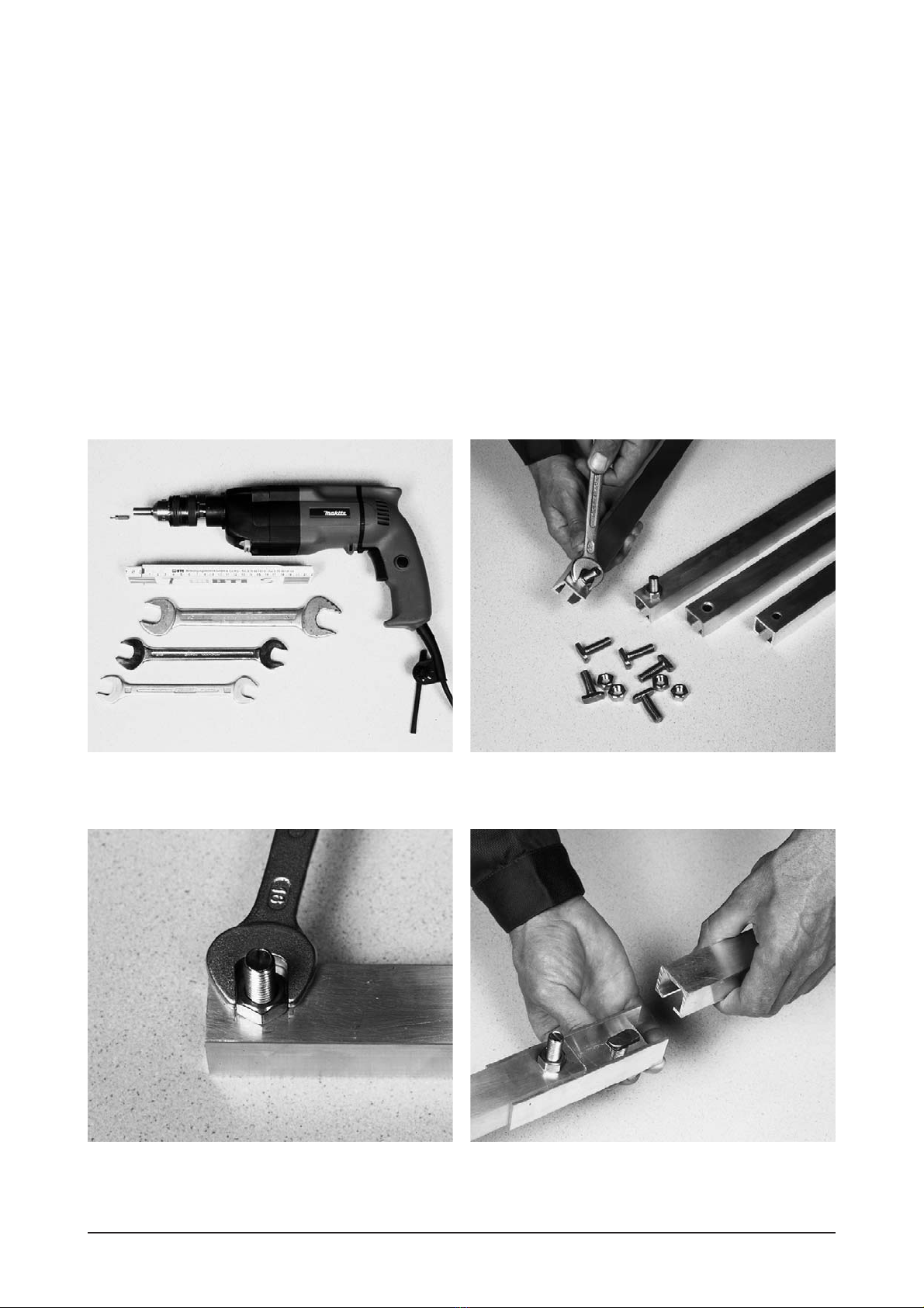
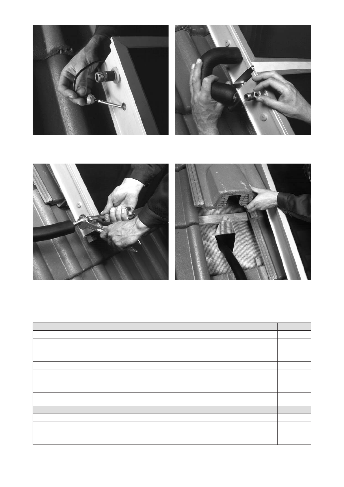
Figure 13 Tools for installation: carpenter’s gauge, drill, screwdriver bit
(cross recess PZ 3), open-ended spanner – sizes 16, 19 and 24 (mm).
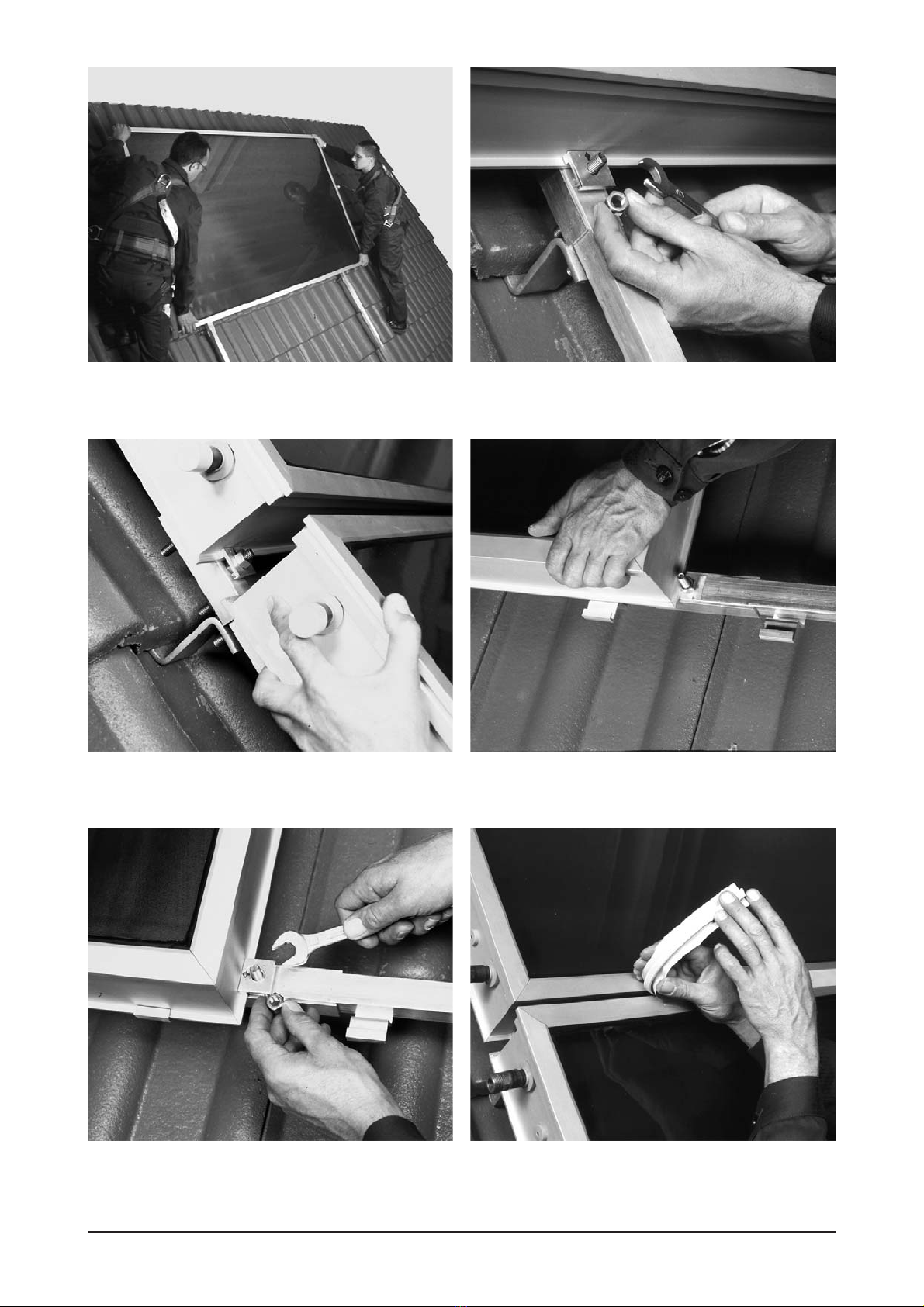
Figure 15 Please ensure that when tightening the bolts the nut sits
square with the long side of the railing. This is important for the fitting
accuracy of the collector.
Figure 14 Prepare the installation railings on the ground. Insert the
hammerhead bolts into all holes in the installation railings from inside
and fasten the nuts.
Figure 16 Connect collector railings (➃, p. 2) and expansion collector
railings (➄,p. 2) with coupling piece using two hammerhead bolts. Push
the railings tightly together.
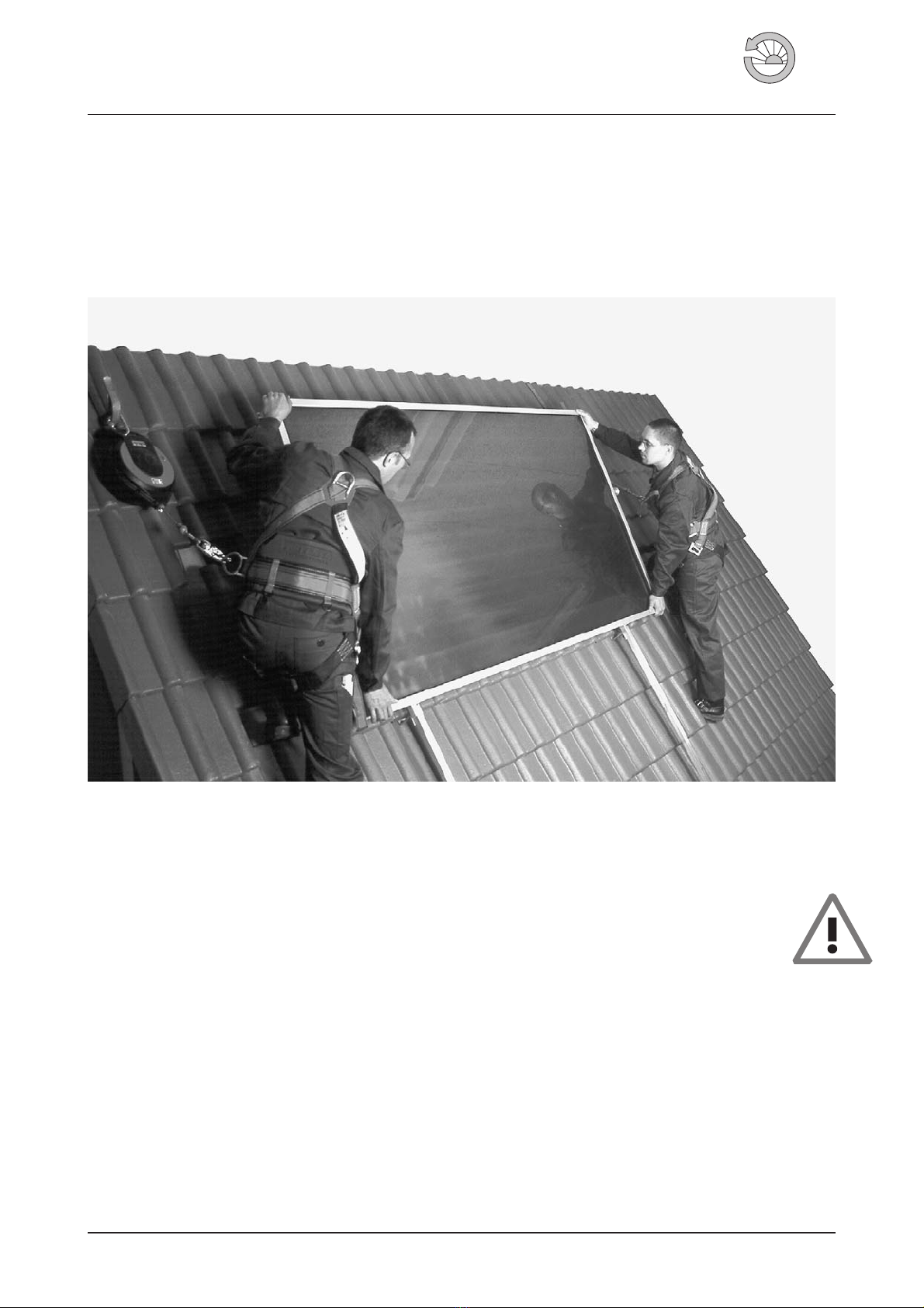
Installation
Please observe the following guidelines before
commencing work and during installation.
You will find some important notes about accident preven-
tion in the leaflet “Safety instructions for collector installa-
tion”.
If collectors have to be stored outside, this can be done in
two ways:
1. Lay down collectors with glass up. Avoid direct ground
contact, e.g. by laying wood beams under collectors. Put
spacers such as wood laths between collectors to avoid
scratches on the glass.
2.Lean collectors with their rear side against a wall or some-
thing similarly solid. Place spacers between collectors.
Don't lay paper or cardboard between collectors. Incorrect
storage can result in humidity entering the collectors.
Prevent damage from frost!
It is not possible to empty collectors completely after pres-
sure testing and rinsing. It is therefore necessary to fill the
system with antifreeze immediately. The volume for one
collector is 1.3 litres of the required mix. Check the concen-
tration level with a frost protection meter. Do not leave pure
water in collectors if there is danger of frost!
We do not accept any responsibility for damages resulting
from not adhering to these instructions.
It is mandatory to follow best practice rules for static plan-
ning, especially those related to wind and snow loads. Dif-
ferent codes and regulations apply in different countries
and regions. For more information please refer to the tech-
nical information “EURO Solar Collector“ C20/C22 and the
leaflet “Notes on Snow and Wind safe Installation of Solar
Collectors“.

6EN-EURO-C20-C22-On-Roof-Installation-MA-0704-11211100
Figure 17 When installing the collectors vertically, you should insert
the two on-roof collector holders before connecting the rails and posi-
tion them to the left and right of the coupler.
Figure 18 When working on the roof please observe the guidelines set
out in the “Safety instructions for collector installation” leaflet.
Figure 19 Measure the area for the collector on the roof and determine
the corresponding fastening points on the roof.
Figure 20 Fix the roof brackets with self tapping screws (6x80). If the
laths are thicker than 30 mm then put a support under the roof brackets.
Figure 21 Align the collector rails at the same height and fix to the roof
brackets with screws so that when tightly fastened, the bolt head lies
perpendicular to the rail.
Figure 22 Carrying handles can be provided on request. Fasten them
to both sides of the collector at the top edge of the collector with fasten-
ing clip (see figure 2) – Check that they are tight.

EN-EURO-C20-C22-On-Roof-Installation-MA-0704-11211100 7
Figure 23 Place the collector onto the two lower bolts of the collector
rails.
Figure 24 Fix the collector to the bottom and top edges with fastening
clips so that the engraved arrow points towards the collector (see close-
up page 2).
Figure 25 Push the bottom edge of the lower collector under the fas-
tening clips and tighten the lower fastening clips so that the arrow
points to the collector.
Figure 26 Only for vertical installation put the collector in the on-roof
collector holder first.
Figure 27 Only for vertical installation then fix the collector with fasten-
ing clips so that the engraved arrow points towards the collector. Then
install the next collector.
Figure 28 Option: Slide or push t-section silicone into the gap be-
tween two collectors.

Figure 29 Pull the plug from the sensor sleeve and push over the sen-
sor. Place sensor in the absorber's sensor sleeve (in centre of frame on
the EURO C22) and close again. Connect cables through the ventilation
tile to the sensor box.
Figure 30 Connect the collectors with corrugated stainless steel tube.
Watch out for the gaskets.
Figure 31 Apply counterforce when tightening to protect collector
connection against damage. If required use wrench to correct distorted
hose.
Materials List
Tab. 1 Components for EURO C20 and EURO C22 Basic kit Expansion kit
Stainless steel hammerhead bolts with nuts M10x30 mm 16 8
Washer, stainless steel 10.5x20 62
Collector rails, length: 1.257 mm (EURO C20); 1.202 mm (EURO C22) 2 –
Expansion collector rails with coupling piece L 1.223 mm (C20); 1.168 mm (C22) 2 2
EURO fastening clips with nuts 62
EUROcollector holder (only necessary for vertical installation) 4 2
Silicone T-profile cover (option) 11
Stainless steel corrugated tubing ½“, Insulation 20x13 mm and gaskets, length 25 cm 1 1
Stainless steel corrugated iron tube with 20x13 mm insulation,
gaskets and solder nipple ½“ / 18, length 90 cm 20
Accessories
Roof bracket type “P STv KF” for interlocking tiles, galvanised each with 3 dry wall screws 6x80 6 2
Roof bracket type “S” for flat tiles/slate, galvanised each with 3 dry wall screws 6x80 6 2
Roof bracket type “W” for corrugated sheeting, galvanised each with 2 screws 8x130, cap and glue 6 2
Roof bracket type "P Al hv" Aluminium with 3 drywall screws 6x80 6 2
Figure 32 Cut the sarking membrane, fold It back, fix it and install the
ventilation tile or roof passage. Connect the corrugated tubes to the so-
lar circuit and pull the insulation against the collectors once the pres-
sure test has been done.
Subject to modifications, errors excepted. · © Wagner & Co, 2007 · www.wagner-solar.com
8WAGNER & CO · Zimmermannstraße 12 · D-35091 Cölbe/Marburg · ☎+49 6421 80 07-0 · Fax 80 07-22
Other manuals for EURO C22
1
This manual suits for next models
1
Table of contents