WAGO I/O System 750 Table of Contents 3
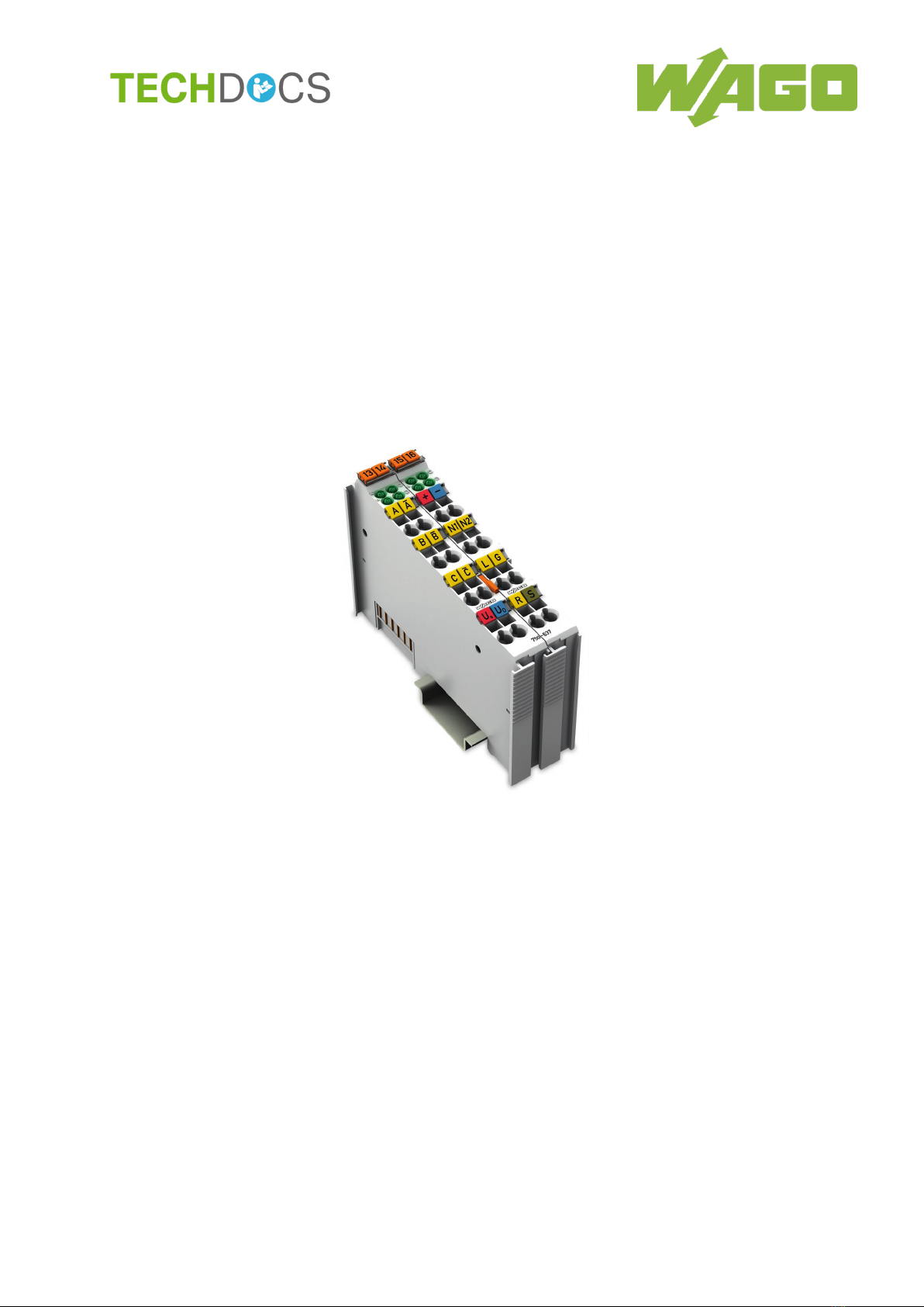
750-637 Incremental Encoder Interfaces
Manual
Version 1.6.1
Table of Contents
1Notes about this Documentation .............................................................5
1.1 Validity of this Documentation.................................................................5
1.2 Copyright................................................................................................5
1.3 Symbols .................................................................................................7
1.4 Number Notation ....................................................................................9
1.5 Font Conventions ...................................................................................9
2Important Notes ......................................................................................10
2.1 Legal Bases..........................................................................................10
2.1.1 Subject to Changes..........................................................................10
2.1.2 Personnel Qualifications ..................................................................10
2.1.3 Use of the 750 Series in Compliance with Underlying Provisions.....10
2.1.4 Technical Condition of Specified Devices.........................................11
2.1.4.1 Disposal ......................................................................................11
2.1.4.1.1 Electrical and Electronic Equipment........................................11
2.1.4.1.2 Packaging...............................................................................12
2.2 Safety Advice (Precautions) .................................................................13
3Device Description..................................................................................16
3.1 View .....................................................................................................18
3.2 Connectors...........................................................................................19
3.2.1 Data Contacts/Local Bus..................................................................19
3.2.2 Power Jumper Contacts/Field Supply ..............................................19
3.2.3 CAGE CLAMP®Connectors.............................................................20
3.2.3.1 Versions 750-637 and 750-637/000-003......................................20
3.2.3.2 Version 750-637/000-001 ............................................................21
3.2.3.3 Versions 750-637/000-002 and 750-637/000-004........................22
3.3 Display Elements..................................................................................23
3.4 Operating Elements..............................................................................25
3.5 Schematic Diagram ..............................................................................25
3.6 Technical Data .....................................................................................27
3.6.1 Device Data .....................................................................................27
3.6.2 Power Supply...................................................................................27
3.6.3 Communication................................................................................27
3.6.4 Inputs/Outputs..................................................................................28
3.6.5 Digital Outputs (N1, N2) ...................................................................28
3.6.6 Digital Inputs (Latch, Gate, Ref) .......................................................28
3.6.7 Quadrature Inputs (A, /A, B, /B, C, /C) .............................................29
3.6.8 Quadrature Decoder ........................................................................30
3.6.9 Climatic Environmental Conditions...................................................31
3.7 Approvals .............................................................................................32
3.7.1 Ex Approvals....................................................................................32
3.8 Standards and Guidelines ....................................................................34
4Process Image.........................................................................................35
4.1 Control/Status Byte...............................................................................37
5Function Description ..............................................................................44