Page 2 of 32
Contents:
1
INTRODUCTION
....................................................................................................................................
3
2
GETTING
STARTED..............................................................................................................................
3
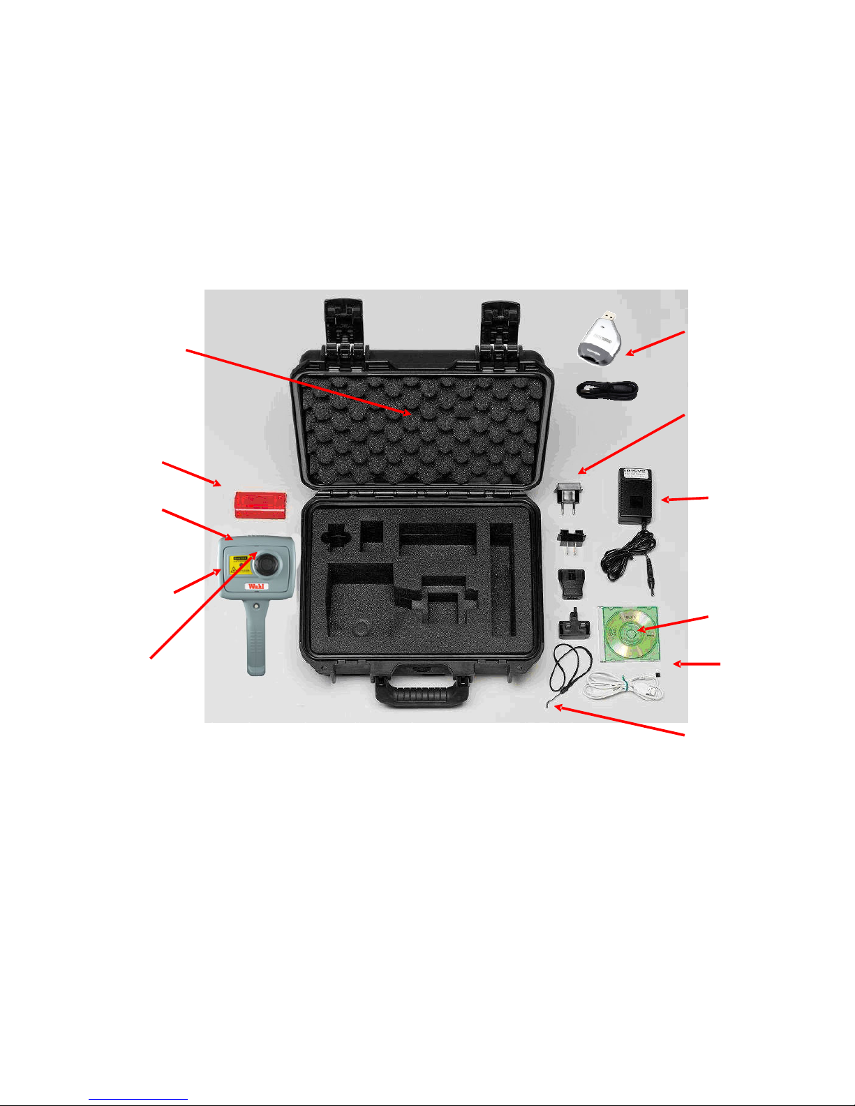
2.1
U
NPACKING
.........................................................................................................................................
3
2.2
P
OWERING THE
HSI3000
.....................................................................................................................
4
2.2.1
Using
Battery
Power
–
Inserting
the
Battery
..............................................................................
4
2.2.2
Using
AC
Mains
Power
..............................................................................................................
4
2.2.3
Battery
Charging
........................................................................................................................
5
3
OPERATING
THE
HSI3000
THERMAL
IMAGER
...........................................................................
5
3.1
H
ARDWARE
.........................................................................................................................................
5
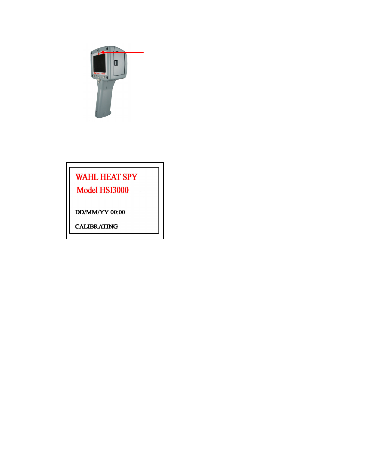
3.2
S
WITCHING ON THE
HSI3000...............................................................................................................
6
3.3
I
NFORMATION
S
PLASH
S
CREEN
...........................................................................................................
6
3.4
U
SING THE
HSI3000
T
HERMAL
I
MAGER
..............................................................................................
7
3.4.1
Focusing.....................
..................................................................................................................
7
3.4.2
Screen Display Items.....
..............................................................................................................
7
3.4.3
Buttons..
.....................................................................................................................................
8
3.4.4
HSI3000
Hot
Button
Operation
..................................................................................................
9
3.4.4.1
Hot
Button
1
–
Zoom
..............................................................................................................................
9
3.4.4.2
Hot
Button
2
–
Freeze/
Save....................................................................................................................
9
3.4.4.3
Hot
Button
3
-
Direction
Buttons
Control.
...............................................................................................
9
3.4.4.4
Hot
Button
4
–
Auto
/
Manual
................................................................................................................
9
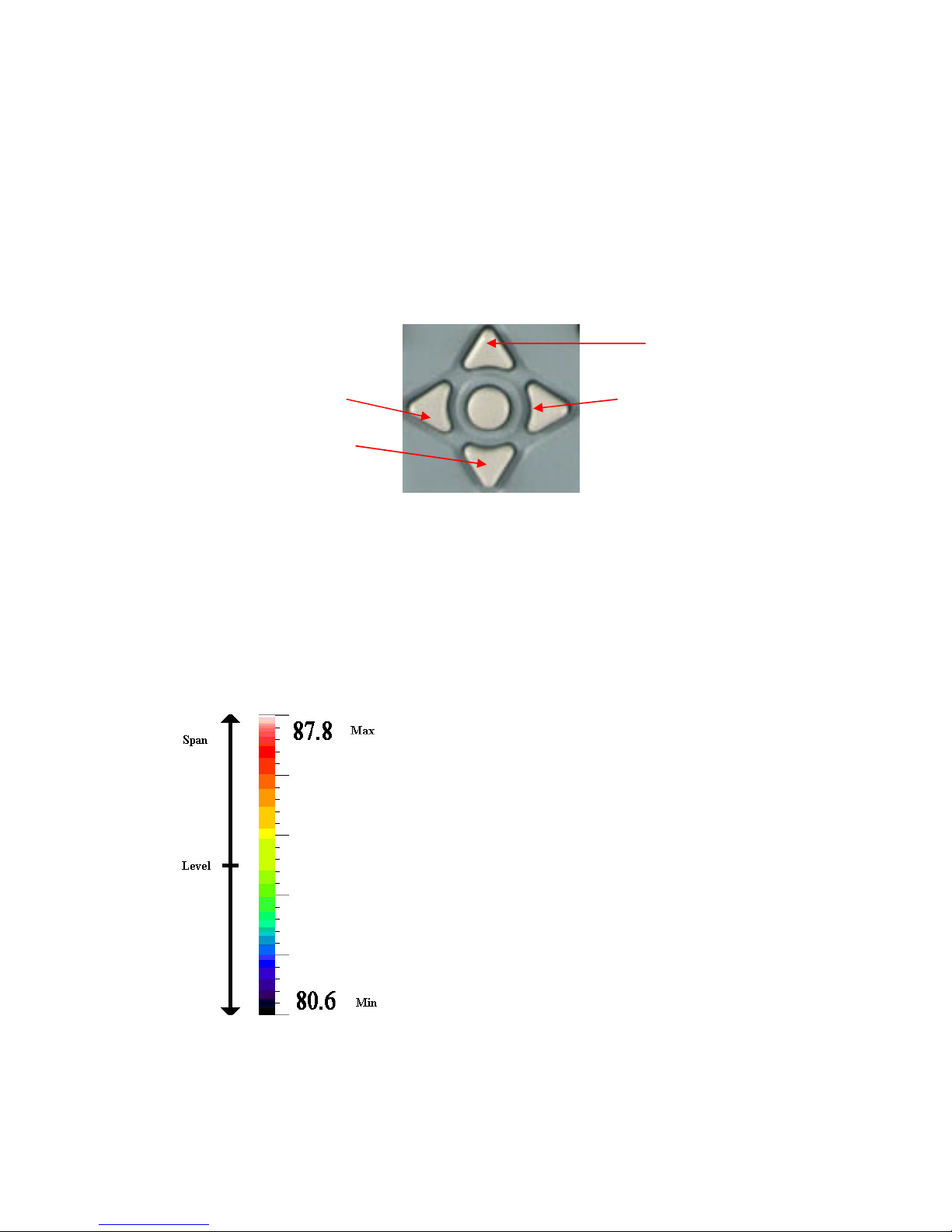
3.4.5
Directional
Buttons...................................................................................................................
10
3.4.6
Image Adjustment........................................................................................................................
10
3.4.6.1
Level and Span Definitions..................................................................................................................
10
3.4.7
Menu Operation and Functions...................................................................................................
11
3.4.7.1
Measurement
Settings
......................................................................................................... .................
11
3.4.7.2
Camera
Settings
....................................................................................................................................
12
3.4.7.3
Image
Browser
Menu............................................................................................................................
12
3.4.7.4
Clock/Calendar
Settings.......................................................................................................................
12
3.4.8
Using the Laser Pointer
.............................................................................................................
13
3.4.9
Advanced User Functions.........................................................................................................
13
3.4.9.1
Brightness & Contrast Definitions........................................................................................................13
3.5
T
ECHNICAL
.......................................................................................................................................
15
3.5.1
Field Of View
...........................................................................................................................
15
4
THERMAL IMAGE TRANSFER FROM
HSI3000
TO A PC
..........................................................
16
4.1
SD CARD .......................................................................................................................................
16
4.2
USB CABLE.....................................................................................................................................
1
6
5
USING
THE
HSI3000
THERMAL
IMAGER
WITH
A
PC
..............................................................
17
5.1
PC
R
EQUIREMENTS
...........................................................................................................................
17
5.2
I
NSTALLATION OF
S
OFTWARE ONTO
PC
............................................................................................
17
5.3
O
PERATING
“Wahl HSI3000
S
ERIES
I
MAGER
”
PC
S
OFTWARE
..........................................................
17
5.3.1
Menus
and
Toolbar...................................................................................................................
18
5.3.1.1
Menus
...................................................................................................................................18
5.3.1.1.1 File
...................................................................................................................................18
5.3.1.1.2 Edit
...................................................................................................................................20
5.3.1.1.3 View
...................................................................................................................................20
5.3.1.1.4 Tools
...................................................................................................................................26
5.3.1.1.5 Help
...................................................................................................................................27
5.3.1.2
Toolbar
...................................................................................................................................27
6
SEQUENCING
......................................................................................................................................
28
7
EMISSIVITY TABLE
...........................................................................................................................
30
8 SPECIFICATIONS.................................................................................................................................. 31
9 CUSTOMER FEEDBACK
....................................................................................................................
32