12 V DC
0,09 - 0,18 l/h
900 - 1800 W
456x343x208mm
8 m
100 cm2
2 m
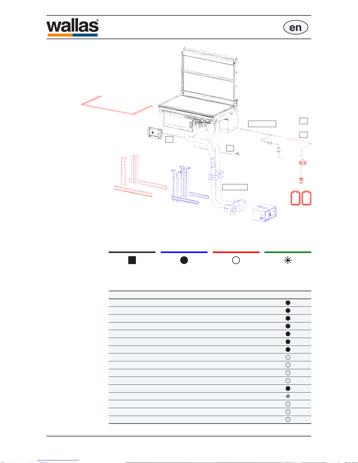
4300
~ 12 kg
en
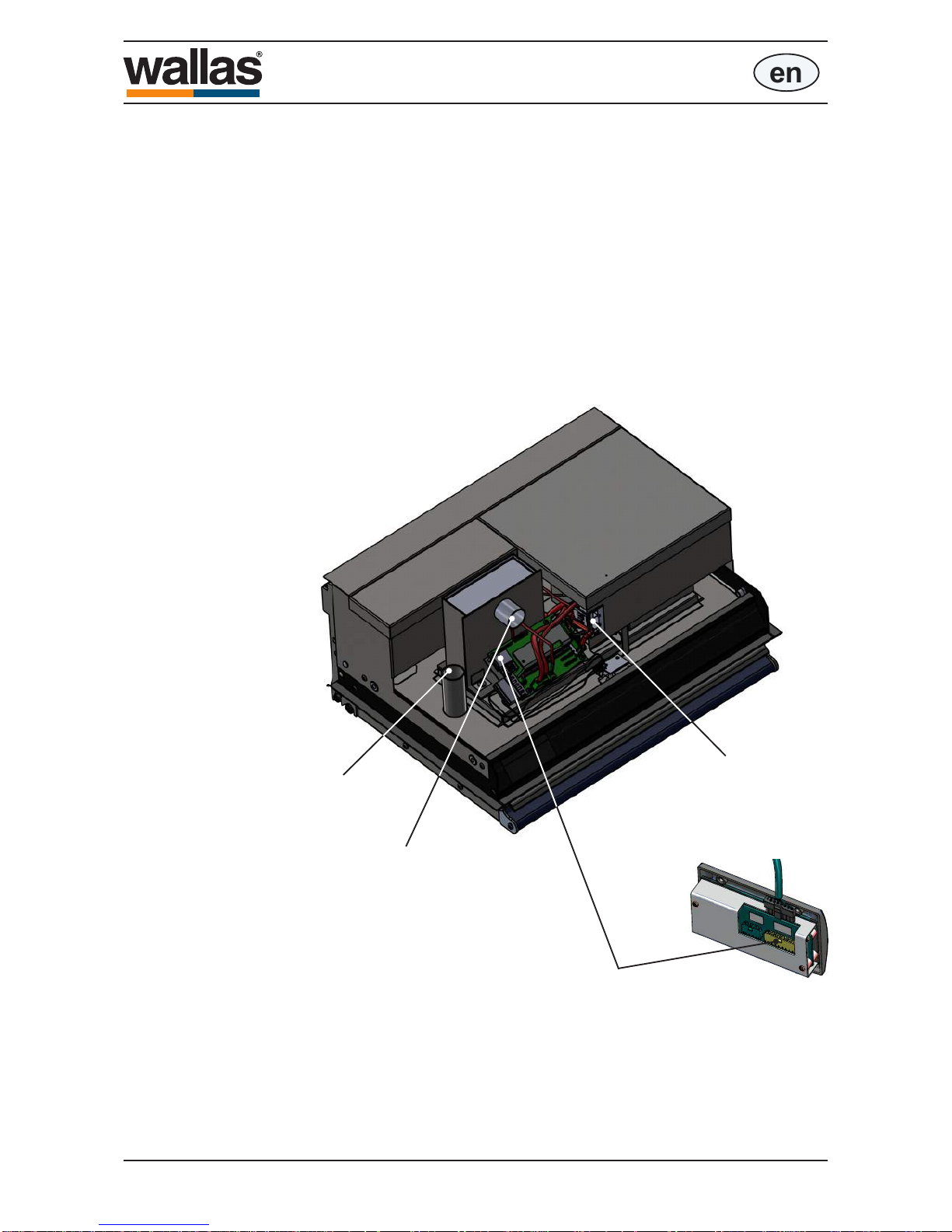
Technical information
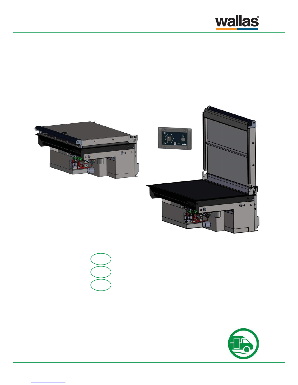
Stove operation
The XC Duoisasafedieselstovewithnoopename.Thestoveisequippedwith
a single burner which burns either diesel oil or light furnace oil (diesel heating oil).
The stove takes the air needed for the burning process from outside of the vehicle
withacombustionairbloweranddischargestheresultantexhaustoutsideofthe
vehicle.
The fuel pump in the stove dispenses fuel, and the electronics control the combus-
tionairandtheamountoffuelautomaticallytokeeptheameoftheburnerclean.
Whenthestoveisrstswitchedon,theglowplugintheburnerignitesthefuelthat
has been pumped into the burner. The glow time begins and ends automatically.
TheheatsensorinthestovedetectstheheatoftheameandlightstheredLED
lighttosignalthattheamehasbeenignited.
The heat which is released as the fuel burns is transferred into the ceramic stove
top. The left side of the stove top is hotter, as the burner is located under it. The
power of the stove can be adjusted steplessly. The control adjusts both sides of the
stove simultaneously.
When the stove is switched off, a cool down cycle begins. The cooling function ven-
tilatestheburneranddischargestheexhaustgasesgeneratedduringcooldown
outside the vehicle.
Thestovelendsitselfextremelywelltocookingandheatingallkindsoffoods.
It has been manufactured entirely from stainless and aluminium materials.
Function as a heater
By lowering the blower lid to the horizontal position, the stove works as a cabin
heater.
Adjustment of heat control works either manually or with the help of control panel
built-in thermostat.
Fuel Diesel oil, light furnace oil (diesel heating oil)
0,55...0.85 A (when ignited ca. 5-10 min. 8 - 10 A)
Operating voltage
Consumption
Heating power
Power consumption
Measurements
Weight
Max.permissiblelengthoftheuegas
pipe
Max. permissible length of the fuel hose
Minimum size of the replacement air
opening
Suitableuegaslead-throughs
Technical information
D80121B
- 43 -