Walvoil DPC130X User manual

DPC130X
Pre-compensated Load Sensing Sectional Valve
ATEX version

D1WWTD02E
2
Service Manual
DPC130X
1st edition - September 2018
Thank you for choosing a Walvoil product.
Your product is the result of advanced technology, careful testing and an ongoing quest for reliability, safety, and higher
performance.
The product must be operated within the parameters contained in technical manual D1WWED03E.
To obtain a long service life, follow the maintenance instructions contained in this manual.
BEFORE READING THIS MANUAL
THIS PRODUCT IS INTENDED TO BE OPERATED CAREFULLY AND RESPONSIBLY BY A QUALIFIED WORKER. IF THIS PRODUCT IS
USED IMPROPERLY, THE MANUFACTURER WILL NOT BE RESPONSIBLE FOR ANY RESULTING INJURY OR DAMAGE TO PERSONS
OR PROPERTY.
Whenever the symbols shown below appear, follow the instructions that are given!
Be sure to perform all operations and maintenance in complete safety.
: identiesspecialinstructionsorproceduresthatmaycauseinjuryordamagetopersonsandproperty
unless followed exactly.
WARNING
Additional information
Thiscatalogueshowstheproductinthemoststandardcongurations.
Please contact Sales Dpt. for more detailed information or special request.
WARNING!
Allspecicationsofthiscataloguerefertothestandardproductatthisdate.
Walvoil, oriented to a continuous improvement, reserves the right to
discontinue,modifyorrevisethespecications,withoutnotice.
WALVOIL IS NOT RESPONSIBLE FOR ANY DAMAGE CAUSED BY AN
INCORRECT USE OF THE PRODUCT.

D1WWTD02E 3
Service Manual DPC130X
_________________________________________________________________________________________ Table of contents
Introduction ............................................page 4
Valve description........................................page 5
General specications ...................................page 9
Storage .................................................page 10
Installation .............................................page 11

D1WWTD02E
4
Service Manual
DPC130X
Introduction _______________________________________________________________________________________________
This manual has been conceived to provide the necessary instructions for a correct and safe usage and handling of DPC130X
control valve, in compliance with ATEX directive.
It contains:
• the control valve description;
• thegeneralspecications;
• the storage rules;
• the installation procedures;
• the handling rules;
• the disassembling and assembling procedures;
• the standard maintenance rules;
• the disposal rules
The customer commits to use the products only according the marking on the control valve and the Service Ma-
nual. The DPC130X is supplied comply with the basic safety and health requirements of the EU directive concerning
design, construction and putting the model into circulation. This declaration is no longer valid if the valve (or the
components) is modied without Walvoil S.p.A. agreement and/or it is used outside the technical specication
specied in the manual.
• Before using the product you must read this Service Manual carefully and understand its contents in order to prevent accidents
or damages.
• Do not carry out assembly, disassembly and/or maintenance activities before consulting this manual.
• Assembly,disassemblyand/ormaintenanceactivitiesmustbecarriedoutbyqualiedpersonnel.
• Always bear in mind that “all workers must act responsibly to ensure their own health and safety and that of others in the wor-
kplace since they can be affected by incorrect actions or omissions as well”.
• Donotmodifytheproduct;incasetheproductismodiedWalvoilcannotbeheldresponsibleforanydamageand/oraccident.
• Always observe standard workplace conditions.
•Before starting any activity, you must ensure thet the machine, plant or system, on which this control valve has to be assem-
bled, is compliant against the explosion risk. Moreover, you must draft the "document of protection against explosion" according
with the ATEX Directive 99/92 EC.
• Walvoil is dedicated to constant product improvement. Hence there may be some differences between the product in your
possession and this manual. If you note some differences, don’t hesitate to contact our After-sales Department for further cla-
rication.
WARNING

D1WWTD02E 5
Service Manual DPC130X
ATEX DPC130X is an open/closed circuit sectional valve:
• its operating principles are based on the precompensated Load Sensing technology;
• which has been conceived to be adequate to work in potential explosive areas according to the requirements of ATEX Directive
2014/34/UE.
_________________________________________________________________________________________ Valve description
Operating principle of Pre-Compensated Load Sensing technology
The main feature of this principle is that the ow rate to the user is proportional to the spool position under any operating
condition, regardless of the resistance encountered by the user (pressure) and the number of activated levers (exceeding the
pump’stotalowrate,aconditionhereinafterdenedassaturation,istheonlylimitation).
V2
V1
LS
TP
B1 A1
L
B2 A2
LSAB LSAB
V2
V1
LS
TP
B1 A1
L
B2 A2
LSAB LSAB
Closed center circuit example
Open center circuit example

D1WWTD02E
6
Service Manual
DPC130X
Valve desctription ________________________________________________________________________________________
ATEX Directive 2014/34/UE
The ATEX Directive 2014/34/UE is applied, with the aim to reduce the risk of use, to the manufacture specications of all
those products to be used in potentially explosive atmosphere due to the presence of dust or gas. According to this directive
anexplosiveatmosphereismadeupfromamixtureofinammablesubstances(likegas,vapours,mistsanddust)withairin
determined atmospheric conditions in which, after triggering, the combustion propagates together with unburned substances.
Anatmospherethatcouldbecomeanexplosiveatmospherebecauseoflocaland/oroperativeconditionsisdenedapotentially
explosive atmosphere.
In order to dene an adequate conformity evaluation procedure, depending on the purpose stated, the manufacterer must
establish the product functioning conditions (e.g. for the working area, the type of the possible explosive mixture and the risk
level of an explosive atmosphere), then to which Group the product belong and determine the category inside the Group.
Areas Gas-Air-type explosive
mixture (G)
Dust-Air-type explosive
mixture (D)
With the Atex Directive 2014/34/UE (for the safety of workers) please
ndtheworkingconditionsforproductsincompliancewithAtexDirec-
tive 2014/34/UE.TheseareexpressedinAreasanddenedaccording
to the potential explosive atmosphere, respectively for every type of
atmosphere (gas-air mix or dust-air mix).
The products due to work in en-
vironments characterized by this
type of explosive atmosphere will
be respectively indicated for Area
0, 1 or 2 depending on the Group
and category of origin (see below)
and they are marked with the let-
ter G.
The products due to work in en-
vironments characterized by this
type of explosive atmosphere will
be respectively indicated for Area
20, 21 or 22 depending on the
Group and category of origin (see
below) and they are marked with
the letter D.
Area 0 and 20
Where an explosive atmosphere is constantly present or present for
long periods or frequently.
Area 1 and 21
Where an explosive atmosphere is probable. It occurs in normal fun-
ctioning and exercise conditions.
Area 2 and 22
Where an explosive atmosphere is scarcely possible or, if it occurs, it
lasts only for a brief period of time.

D1WWTD02E 7
Service Manual DPC130X
__________________________________________________________________________________________ Valve description
ATEX Directive 2014/34/UE
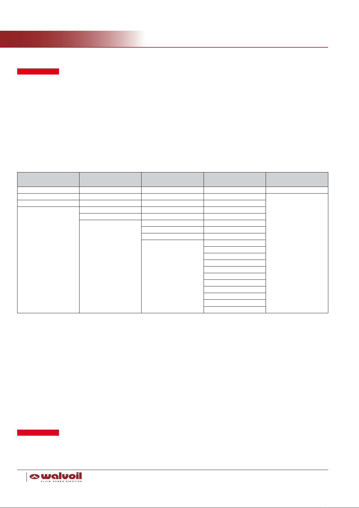
PleasendbelowtheATEXcategoriesonWalvoilDPC130Xvalve
II 2G Ex h IIC T4 Gb
II 2D Ex h IIIC T130°C Db
I M2 Ex h I Mb
MiningcategorycanbeaddedinsomespecicDPC130Xcongurations.
Group I Group II
Includestheequipmentdestinedtobeusedinundergroundjobsinthe
minesandtheirsurfaceplants,exposedtotheriskofreleaseofre-
damp and/or combustible dust. The subdivision into categories depends
on the eventual power supply interruption in case of explosive atmos-
phere due to a mixture of air and gas, vapours mists (D) or a mixture
of air and dust (G).
Includes the equipment to be used in different environments (from the
mines) with possible explosive atmosphere. Their subdivision into cate-
gories depends on two fators: the place, where the product will be used
and the possible potentially explosive atmosphere, due to the mixture
of air and gas, vapours, mists (D) and the mixture of air and dust (G).
It can occur in a constant or occasional manner and for long or brief
period of time.l
Category M1: Very high protection level Category 1: Very high protection level
These products must keep on working, for safety reasons, in the pre-
senceofanexplosiveatmosphereandspecicperformancesorprotec-
tioncongurationsforbreakdownincaseofexplosion.
These products have to work, in compliance with operative parameters
established by the Manufacturer, in environments with a high probabi-
lity of frequent or long lasting explosive atmospheres. They must pre-
sentspecicperformancesorprotectioncongurationsforbreakdown
in case of explosion.
Category M2: High protection level Category 2: High protection level
The power supply to these products must be interrupted in case of
an explosive atmosphere. Protection means must be incorporated to
guarantee the protection level during normal functioning and also in
oppressive working conditions or resulting from great stress.
These products have to work, in compliance with operative parameters
established by the Manufacturer, in environments with a high probabili-
ty of explosive atmospheres. Protection against explosions in this case
must guarantee the required safety level even in presence of equip-
ment functioning defects or in dangerous operative conditions, which
frequently must be taken into consideration.
Category 3: Normal protection level
These products have to work, in compliance with operative parameters
established by the Manufacturer, in environments with a slight proba-
bility of explosive atmosphere, which may occur, however only rarely
or for a brief period of time. This type of product, belonging to the
category concerned must guarantee the safety level required in normal
functioning conditions.
The EPLs were chosen in accordance with possible ignition sources and normal operation and expected malfunctions analysis
(Explosion Risk Assessment).

D1WWTD02E
8
Service Manual
DPC130X
product serial number
(production year
included)
Type E F Weight
mm in mm in Kg lb
DPC130/1 184 7.24 200 7.87 12.4 27.3
DPC130/2 232 9.13 248 9.76 19.4 42.8
DPC130/3 280 11.02 296 11.65 25.3 55.8
DPC130/4 328 12.91 344 13.54 31.0 68.3
DPC130/5 376 14.80 392 15.43 36.5 80.5
Valve description _________________________________________________________________________________________
Dimensional data
II 2G Ex h II T4 Gb - II 2D Ex h IIIC T130°C Db
I M2 Ex h Mb - T amb -20÷60°C T fluid -20÷80°C
Via Adige 13/D
42124 Reggio E. Italy
CE mark
DATAMATRIX
ATEX mark
manufacturer reference
ATEX category
environmental temperature uidtemperature
E
F
230
9.06
54.5
2.15
5
0.197
43.5
2.01
11
0.43
45.5
1.79
8
0.31
9
0.35
8
0.31
152
5.98
130.4
5.13
100
3.94
293.5
11.56
Ø 8.5
Ø 0.33
8
0.31
4.7
0.19
33
1.30
33.5
1.32
33.5
1.32
116
4.57
81
3.19
48
2.01
50
1.97
53
2.09
37.1
1.46
10
0.39
16
0.63
16
0.63
P
A1A2
B1B2 T
L
LS
product code
product name
Type E F Weight
mm in mm in Kg lb
DPC130/6 424 16.69 440 17.32 42.6 93.9
DPC130/7 472 18.58 488 19.21 48.7 107.0
DPC130/8 520 20.47 536 21.10 54.8 121.0
DPC130/9 568 22.36 584 22.99 60.9 134.0
DPC130/10 616 24.25 632 24.88 67.0 148.0

D1WWTD02E 9
Service Manual DPC130X
___________________________________________________________________________________ General specications
Working conditions
Thiscatalogueshowstechnicalspecicationsanddiagramsmeasuredwithmineraloilof46mm2/s - 46 cSt viscosity at 40°C - 104°F
temperature.
Nominalowrating
(open center circuit)
on inlet port with compensator
@ stand-by (margin pressure) 150 l/min - 39.6 US gpm @ 9 bar - 131 psi
on working ports with compensator
@ stand-by (margin pressure) 100 l/min - 26.4 US gpm @ 7 bar - 102 psi
on working ports without compensator
@ stand-by (margin pressure) 130 l/min - 34.3 US gpm @ 9 bar - 131 psi
Max. pressure P inlet port 315 bar (1) - 4500 psi (1)
Aand B working ports 315 bar (1) - 4500 psi (1)
Back pressure (max.) on Toutlet port 25 bar - 363 psi
on L drain port 2.5 bar - 36 psi
Standard internal
leakage A(B)->T
∆p=100bar- 1450 psi 16 cm3/min - 0.98 in3/min
withportvalves,∆p=100bar-1450 psi 21 cm3/min - 1.28 in3/min
Fluid Mineral oil
Fluid temperature range with seals NBR (BUNA-N) from -20°C to 80°C - from -4°F to 176°F
with seals FPM (VITON) from -20°C to 80°C - from -4°F to 176°F
Viscosity
operating range from 15 to 75 mm2/s - from 15 to 75 cSt
min. 12 mm2/s - 12 cSt
max. 400 mm2/s - 400 cSt
Contamination level max. -/18/15 - ISO 4406 - NAS 1638 class 9
Environmental
temperature for working conditions from -20°C to 60°C (2) - from -4°F to 140°F (2)
Environmental
pressure for working conditions from +0.8 to + 1.1 bar - from +11.6 to 16 psi
NOTES: (1)AccordingtoNFPAT2.6.1.,fatigueratingveriedfor1millioncycleson6samplevalveswithtestPressure=1.23xMax.pressure
indicated - (2) DPC130X can operate with gases with an ignition temperature above 135°C - 275°F and powders with an ignition temperature
above 130°C - 266°F.
REFERENCE STANDARD
BSP UN-UNF
THREAD
ACCORDING TO
ISO 228/1 ISO 263
BS 2779 ANSIB1.1unied
CAVITY
DIMENSION
ACCORDING TO
ISO 1179 11926
SAE J1926
DIN 3852-2, X or Y shape
PORTS BSP UN-UNF
P inlet G 3/4 1 1/16-12 (SAE 12)
Aand B ports G 1/2 7/8-14 (SAE10)
T outlet G 3/4 1 1/16-12 (SAE 12)
LS Load Sensing G 1/4 9/16-18 (SAE 6)
V1 pilot G 1/4 9/16-18 (SAE 6)
V2 pilot depends on inlet section type:
see pages from 14 to 17 (5)
L drain G 1/4 7/16-20 (SAE 4)
M pressure gauge G 1/4 9/16-18 (SAE 6)
Hydraulic control ports G 1/4 9/16-18 (SAE 6)
NOTES (5): ATTENTION! V2 pilot port requires dedicated
joints;pleaseseeInletsectionpages.
NOTES (3): Standard pressure series - (4): For pressure up to 350 bar
(5100 psi)
Standard thread

D1WWTD02E
10
Service Manual
DPC130X
General specications___________________________________________________________________________________
• Never use the control valve at a pressure exceeding the rated pressure in order to avoid to breack it;
• usethecontrolvalvewithintheratedowinordertoavoidmalfunctionoradeteriorationintheheatbalance.Ifthecontrol
valveisusedbeyondtheveriedworkingconditionsrange,weshallnotberesponsibleforanyaccidentwhichmayaccur;
• donotuselow-cleanlesshydraulicuidinordertoavoidsealfailureordamagetosealparts,whichcouldcausethemachine
operation failure or an operation mistake;
• usethecontrolvalveattheenvironmentalconditionsspeciedinthepreviousdatasheet.IftheControlValveisusedoutside
thespeciedrange,weshallnotberesponsibleforanyaccidentwhichmayoccur;
• Usethecontrolvalvewiththeworkinguidspeciedinthismanual.Ifthecontrolvalveisusedbeyondthespeciedrangeor
withdifferentworkinguidproperties,weshallnotberesponsibleforanyaccidentwhichmayoccur.
For any doubt please contact our After-sales Department.
WARNING
WARNING
Cast iron O-ring seals
& Parback Spring steel Other steel Other
Cast iron EN-GJl-250 NBR 70 Sh AISI 302 11SMnPb37 Sint. A50
Cast iron EN-GJL-300 VITON 75 Sh VDSiCr EN10270-2 16CrNi4Pb
Cast iron EN-GJV-300 NBR 90 Sh FDCrSI 36SMnPb14
Teon(PTFE) Quench Steel 35SMnPb10
Poliurethane AISI 302 Class B Steel
AISI 316 INOX Steel
OTEVA 60 INOX A2/304 Steel
OTEVA 70 X10CrNiS1809
3CD60 Steel
Class 8.8 Steel
Class 10 Steel
Class 10.9 Steel
Class 12.9 Steel
C43
ETG100
Fe37
MIM 4605
Sint. C39
Sint. D35
All the material installed by the manufacturer are in accordance with UNI CEI EN ISO 80079-36:2016
Do not store the Walvoil product:
• in places where it could be damaged;
•outsideatemperatureandpressurerangespeciedinenvironmentaldatasheet(seepag.7);
• where it could get wet;
• where it could come in contact with organic solvents, acids, alkalis and/or dangerous gases;
•inplacessubjecttosudden,signicanttemperaturechanges;
• in zones where a potential explosive atmosphere can occur also with a very low probability.
•removethepackagingonlyjustbeforeassemblingtheproduct;
• Walvoil is not responsible for any damage due to a storage not in compliance with our prescriptions;
• for any doubt, please contact our After-sales Department.
Storage ______________________________________________________________________________________________________

D1WWTD02E 11
Service Manual DPC130X
_________________________________________________________________________________________________ Installation
When you receive these Walvoil products, please check:
• if there are signs of damage of the packaging;
• that the dimensions of the product seat are compatible with those of the product itself;
• that the assembly seat is compatible with the part dimensions and that it has been prepared for the valve set-up (connection
hoses ready etc.);
Before starting the assembling, be sure that the mounting zone is not a potential explosive atmosphere (even with a very low
probability).
• remove the plastic plugs that protect the ports and be careful not to introduce any dirt or foreign matter inside the control valve
as this could damage it;
•mountthecontrolvalvesafelyoveraatsurface(recommended3xingpoint);atthesametimedonotuseahammerfor
positioning by hitting; any assembly distortion can cause spool sticking and poor control;
• clean hoses before using them;
• prevent the presence of dust or foreign matters in port inlets;
• double check that hoses are correctly connected according to the prescription and indication of the hydraulic schema, especially:
- (in case of electrohydraulic control) be sure that drain line is directly connected to tank (avoid any back pressure)
- (in case of variable displacement system) be sure that LS signal line is correctly connected to the pump regulator
• tighten the port connectors safely with the recommended fastening torques (Nm) as shown in the following table;
• install the valve in a protected environment, avoiding direct exposure to weathering, water, salt or any other corrosion substan-
ces, powder or other potential explosive substances or gases.
NOTE – These torque are recommended. Assembly tightening torque depends on many factors, including lubrication, coating
and surface nish.
FITTING TIGHTENING TORQUE - Nm / lbft
THREAD TYPE P inlet port A and B
workports T outlet port LS signal port
V pilot ports* L drain port Hydraulic
control ports
BSP G 3/4 G 1/2 G 3/4 G 1/4 G 1/4 G 1/4
With O-Ring seal 90 / 66.4 50 / 36.9 90 / 66.4 25 / 18.4 25 / 18.4 25 / 18.4
With copper washer 90 / 66.4 60 / 44.3 90 / 66.4 30 / 22.1 30 / 22.1 30 / 22.1
With steel and rubber
washer 70 / 51.6 60 / 44.3 70 / 51.6 16 / 11.8 16 / 11.8 16 / 11.8
UN-UNF 1 1/16-12
(SAE 12)
7/8-14
(SAE 10)
1 1/16-12
(SAE 12)
9/16-18
(SAE 6)
9/16-18
(SAE 6)
9/16-18
(SAE 6)
With O-Ring seal 95 / 70 50 / 36.9 95 / 70 30 / 22.1 30 / 22.1 30 / 22.1
(*) V2 port is M14x1.5 threading: tightenìng torque value is the same of G1/4 thread
T
L
LS
P
V1
V2
B
A

D1WWTD02E
12
Service Manual
DPC130X
Installation_________________________________________________________________________________________________
Handling precautions ___________________________________________________________________________________
• A fall or a hit to the control valve could bend the spool and cause an accident due to an operation failure;
• in case the control valve is mounted on a uneven surface, the control valve body might be deformed and cause a malfunction
or external leakage;
• in case foreign matters are present in each port, the control valve operation might fail and cause an accident;
•donottightenttingswithtorqueatthehighervaluethantherecommendedone,sotoavoidstrainsordamagetothecontrol
valve and serious accidents;
• in case the hoses are not connected to the correspondent ports, unintentional movements might cause a serious accident;
• Walvoil is not responsible for any damage due to an installation procedure not in compliance with our prescriptions;
• in case the control valve has to be painted, make sure that surface paint on the control valve does not exceed the maximum
layer of 0.2 mm - 7.87x10⁻³ in(checkifthepaintisammableandincompliancewiththepotentialexplosiveworkingatmosphere
of thr control valve);
• in case of the presence of electrohydraulic controls or unloading valve, please cover these electronic parts (as well as the cables)
before painting;
• avoid painting the marking label;
•fortheelectricpartspleaserefertothemanualsofthesecertiedcomponentsattachedtotheservicemanual.Payparticular
attentiontothewireconnectionanddonotremoveanypartbeforereadingthespecicmanual.Donotsubstitutewire,clamps
and brasscable before reading these attachments. Pay attention to the special conditions for safe use at page 16 of the Thomas
"Ex-relevantAdditionstothePerformanceSpecicationforEx-Valves"Manual;
•Walvoiladvisestomonitorsteadilytheuidtemperaturethroughapropersensor(atleastSIL2)duringthemachinerunning.
Incasetheuidtemperatureexceedsthevalueshowninthegeneralspecications,themachinemustbestoppedimmediately.
• all the personnel involved in the installation, use, maintenance of this valve, must be instructed with the technical information
about all the operations in order to work safely in ATEX atmosphere;
• any change made on this valve can invalidate the safety requirements. For any doubt, please contact our After-sales Department.
When the control valve is handled, make sure:
• that you do not drop, hit or damage the product;
• that you do not hold the pilot cover or return spring cap of the spool or accessory valves such as main relief valves, anti-shock
relief valves and hydraulic compensators plugs.
WARNING

D1WWTD02E 13
Service Manual DPC130X
_____________________________________________________________Disassembly and assembly procedures
Disassembly and assembly should be carried out by Walvoil technicians. In case the control valve doesn’t work properly, we advise
you to contact our After-sales Department.
However in case the disassembly and assembly operations are absolutely unavoidable, you must observe the following prescrip-
tionsandassigntheseoperationstohighlyqualiedtechniciansintheeldofhydraulics.
Do not disassembe the control valve when an explosive atmosphere is present and the control valve surface temperature is outside
theenvironmentaltemperaturerangeasspeciedbefore(seepage9).
• The valve can keep high internal pressure; release the inside pressure and make sure that all machine actuators are in a rest
positionbeforeremovingthepiping.Inanycaseunscrewsafelyandcarefullyconnectionsandttings,sotoavoidafallofloador
high-temperaturehydraulicuidjet.Remindtowearthesafetyequipmentandgoggles;
• do not remove electrical parts by removing the cable or by opening these components; in case these operations are absolutely
unavoidable, please contact out After-sales Department;
• since hydraulic devices are all precisely machined with very accurate clearances, carry out the disassembly and assembly work
in a clean place;
• make sure to prevent dust, sand and other similar powder materials from entering into the device;
• before removing the hoses, attach suitable indications on them so to be able to locate their positions later on. It is also advisable
to label dismounted parts and to write down their original location;
• before disassembling, read and strictly observe the assembly/disassemby instructions (shown in the following paragraph).
• since disassembled parts might show rust, apply them anticorrosive oil and seal them;
• before assembling the control valve on the operating machine, again make sure it has not been affected by the various hydraulic
tests (e.g. relief valve setting, leak test...).
First phase: preassembling
• Collect tie rods kit according to the BOM.
• Collect inlet plate, sections and endplate according to the BOM.
• Collect OR kits according to the BOM.
• Clean carefully grinded planes.
• Starting from the inlet plate, screw by hand the tie rods (from the side of the shorter thread) on the inlet plate.
• Mount the working sections according to the scheme.
• Mount the end plate.
• Put on the spring-washers on the tie rods and screw the nuts by hands.
•Settlethecontrolvalveelementsonarigidplaneandnallyscrewthenutstothetorqueof30Nm-22 lbft.
(A) Assembling kit
For valve with:
With inlet section type
BR-BN-BRS
Part code
With inlet section type BRF
Part code
1 working section 5TIR108185 5TIR108153
2 working sections 5TIR108232 5TIR108201
3 working sections 5TIR108281 5TIR108249
4 working sections 5TIR108328 5TIR108297
5 working sections 5TIR108376 5TIR108339
6 working sections 5TIR108425 5TIR108393
7 working sections 5TIR108472 5TIR108440
8 working sections 5TIR108520 5TIR108488
9 working sections 5TIR108568 5TIR108536
10 working sections 5TIR108616 5TIR108584
A
A

D1WWTD02E
14
Service Manual
DPC130X
Disassembly and assembly procedures ____________________________________________________________
Second phase: valve and plug assembly
• Mount valves according to the BOM and scheme;
• mount plugs according to the BOM and scheme;
• screw valves and plugs to the required torque;
• if required, punch elements according to the scheme.
Third phase: control valve assembly
• Collect tie rods kit according to the BOM;
• collect inlet section, working sections and outlet section according to the BOM;
• collect OR kits according to the BOM;
• clean carefully grinded planes;
• starting from the inlet section, screw by hand the tie rods (from the side of shorter thread) on the inlet section;
• mount the working sections according to the scheme;
• mount the outlet section;
• put on the spring-washers on the tie rods and screw the nuts by hands;
•settlethecontrolvalvesectionsonarigidplaneandnallyscrewthenutstothetorqueof30Nm-22 lbft.
• All the disassembly and assembly operations must strictly observe the procedures listed in this disassembly/assembly instruc-
tion;
• Walvoil is not responsible for any damage due to disassembly and assembly procedures not in compliance with our prescriptions;
• please remember that all these operations have to be carried out in a non potential explosive atmosphere at the environmental
conditions required;
• for any doubt, please contact our After-sales Department.
WARNING

D1WWTD02E 15
Service Manual DPC130X
Do not carry out maintenance operations on the control valve when an explosive atmosphere is present and the control valve
surfacetemperatureisoutsidetheenvironmentaltemperaturerangeasspeciedbefore.
It is advisable to periodically check the parts shown in the table below.
___________________________________________________________________________ Standard maintenance rules
______________________________________________________________________________________________________ Disposal
Reference Item to be checked
General installation Verifyvalveiscorrectlyandsafelyxedinitsseat
Check electric connector and wire condition and wear
Cleanthevalvecarefully,avoidingdirectjet,especiallyonelectricpartsandconnections
In order to prevent rust, dry the valve after cleaning, avoiding scratching and damaging external
surfaces
Periodically check the tightening of:
- Tie rods
- Lever box
- Control kit screws
- Unloading screw
- Electrohydraulic valve screws
-Hydraulicttings
Constantly check oil contamination status and plant lter condition. Contamination may bring to
several malfunctions
Body Check presence of excessive rust and corrosion and replace parts or complete valve if needed
Spool Check presence of scratch, rust and corrosion. It may bring to seals damage or spool sticking. Re-
place parts if needed
Apply grease on spring, lever or positioning kits if the spool operation is not sliding
Sealing Check and replace any possible hardened, de-formed or damaged O-ring. Check and replace the
O-ring also in case its surface is dirty or shows particles.
LS Valve and Auxiliary Valves Periodicallycheckpressuresettingvalues,ifnotcorrectadjustreliefvalvesandsafelylockthenut
at appropriate torque
Electric components Please refer to attached service manual of these components
Whenthecontrolvalvehastobedisposed,rstdrainthehydraulicuidcompletelyanddisposeofitasindustrialwaste.

WWW.WALVOIL.COM
1st edition - September 2018
D1WWTD02E
Table of contents
Other Walvoil Control Unit manuals