Nexta Tech TOP-ML/One User manual

Electronic control unit for the automation of one 230Vac motor with built-in limit switch and 1, 2 or 3 led line in costant
voltage tension (number of led output settable).
Motor and control unit power supply: 230Vac
Led power supply: 12 or 24Vdc
Motor output: 230 Vac max 1000 W
Led output: 5A for output (3out), max 10A in total
433.92 MHz receiver for radio transmitters.
WiFi connection for OneSmart App.
Top-ML/One: control unit in IP20 casing
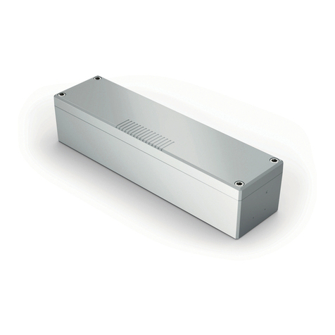
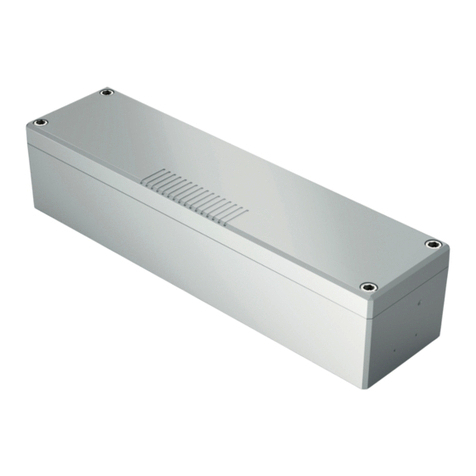
Screen-ML/One: control unit in outdoor plastic box IP56
TOP-ML/One
SCREEN-ML/One
Top-ML400/OneScreen-ML400/One

INDEX
1 - PRODUCT FEATURES
1.1 - TECHNICAL DATA
1.2 - SENSOR MANAGEMENT
Page 3
Page 3
2 - MOTOR AND SENSORS ELECTRICAL CONNECTIONS Page 4
3 - LED OUTPUT ELECTRICAL CONNECTIONS
3.1 - CONNECTING ONE LINE OF SINGLE-COLOUR STRIP LIGHTS
3.2 - CONNECTING TWO LINES OF SINGLE-COLOUR STRIP LIGHTS
3.3 - CONNECTING THREE LINES OF SINGLE-COLOUR STRIP LIGHTS
3.4 - PROCEDURE FOR SETTING NUMBER OF LED OUTPUT
Page 5
Page 6
Page 7
Page 8
4 - SETTING UP CONTROL UNIT Page 9
5 - MANAGEMENT WITH REMOTE CONTROL
5.1 - RADIO PROGRAMMING
5.2 - DELETION OF REMOTE CONTROL
Page 10
Page 11
6- ADVANCED PROGRAMS
6.1 - CONFIGURATION OF MANOEUVRE TIMES
6.2 - CONFIGURATION OF THE FUNCTIONALITIES OF THE SENSORS
6.3 - CONFIGURATION OF THE FUNCTIONALITIES OF THE SENSORS
6.4 - SETTING THE DEVICES CONNECTED TO THE WIRED INPUTS
6.5 - RESET OF THE CONTROL UNIT
Page 12
Page 13
Page 14
Page 15
Page 16
7 - INSIGHTS INTO SENSOR MANAGEMENT
7.1 - SIGNALLING OF ALARMS Page 17
8 - CONTROL WITH APP ONE SMART
8.1 - APP CONNECTION Page 18
9 - INSIGHTS - WIFI CONNECTION
9.1 - ISSUES WHEN CONNECTING THE CONTROL UNIT WITH WIFI Page 19
2

1 - PRODUCT FEATURES
1.1 TECHNICAL DATA
Control unit power supply (Input) 230 Vac
Led power supply 12 or 24Vdc
Motor Output 230Vac max 1000W
Led output 5A for output, max 10A in total
Number of programmable transmitters 30
Receiver frequency RF 433.920MHz
Operating temperature -10° +55°
Dimensions (Top-ML) 174 X 46 h 35 mm
Dimensions (Screen-ML) 310 x 80 h 70mm
1.2 SENSOR MANAGEMENT
The control unit is designed to manage weather sensors to be connected by wire, which if they intervene can
automatically move the motor.
Compatible sensors are:
WIND:
ALARM: the control unit detects a wind speed higher than the one set, for 10 seconds. Then the control unit turns fully
opens the motor (settable function) and disables the reception of remote or wired commands until the alarm is over.
ALARM NOT PRESENT/END OF ALARM: the control unit detects a wind speed lower than the one set, for 60 seconds.
RAIN
ALARM: the sensor detects water: then the control unit close the motor (settable function) and disables the reception of
remote or wired commands until the alarm is over.
ALARM NOT PRESENT/END OF ALARM: the sensitive part of the rain sensor is dry.
SUN
ALARM: the sensor receives direct light for a period of more than 10 minutes: then the control unit close the motor
(settable function) and disables the reception of remote or wired commands until the alarm is over.
ALARM NOT PRESENT/END OF ALARM: the sensor is in the shade or a command is received
ATTENTION:
If more than one sensor is used, there is the possibility that two alarms may intervene which could require confLicting
interventions.
In these situations, the control panel applies a priority according to this order:
- wind sensor
- rain sensor
- sun sensor
Example:
The wind alarm goes off and the motor must open, but the sun is present and the motor should also close.
The control unit gives priority to the wind sensor and then opens. If the wind alarm is over, the sun is still present, the
motor will close.
3

2 - MOTOR AND SENSORS ELECTRICAL CONNECTIONS
WARNINGS
• Installation must be carried out only by qualied technicians in compliance with the electrical and safety standards in
force.
• All connections must be made with the power turned off.
• Use suitable cables.
• Do not cut through the aerial
• A suitably sized disconnection device must be set up on the electric power line that supplies
the product
• Disposal of waste materials must fully respect local standards.
• Do not exceed the load limits shown and use protected power supply units of the correct size for the load.
* NOTE:
• The operation of the inputs can be set, see paragraph 6.4
• See paragraph 3 for connecting the LEDs and setting the number of outputs
TERMINAL
NUMBER
DESCRIPTION
1 230V phase power supply
2 230V neutral power supply
3 230V phase (for accessories power supply)
4 230V neutral (for accessories power supply)
5 Motor ouput, close (L)
6 Motor output, common (N)
7 Motor ouput, open (L)
8 230V phase (for accessories power supply)
9 230V neutral (for accessories power supply)
10 + output led
11 + output led
12* OUT led 1 (-)
13* OUT led 2 (-)
14* OUT led 3 (-)
15 Not used
16* Input 2: default= rain sensor
17 433,92MHz antenna signal
18 Not used
19 Not used
20 Led power supply + (12 or 24Vdc)
21 Led power supply -
22 Input common
23* Input 1: default= vento
ANT
L
(in)
(out)
(out)
L N
N
L N
M
Input 2, rain sensor*
Input 1, wind sensor*
Input common
17 18 19 20 21 22
10 11 12 13 14 15 16
23
1 2 3 4 5 6 7
8 9
4

TERMINAL
NUMBER
DESCRIPTION
1 230V phase power supply
2 230V neutral power supply
3 230V phase (for accessories power supply)
4 230V neutral (for accessories power supply)
5 Motor ouput, close (L)
6 Motor output, common (N)
7 Motor ouput, open (L)
8 230V phase (for accessories power supply)
9 230V neutral (for accessories power supply)
10 + output led
11 + output led
12* OUT led 1 (-)
13* OUT led 2 (-)
14* OUT led 3 (-)
15 Not used
16* Input 2: default= rain sensor
17 433,92MHz antenna signal
18 Not used
19 Not used
20 Led power supply + (12 or 24Vdc)
21 Led power supply -
22 Input common
23* Input 1: default= vento
3 - LED OUTPUT ELECTRICAL CONNECTIONS
This control unit can manage 1, 2 or 3 lines of single-colour LED strip lights.
By default, operation is set to one li strip lights. If a different strip type is used, follow the paragraph 2.4 procedure.
3.1 CONNECTING ONE LINE OF SINGLE-COLOUR STRIP LIGHTS
With the default settings the control unit is set to control the three LED lines with synchronized operation.
WARNING:
• Connect up to 5A per output and max total 10A
• The outputs are synchronized
• The operation of the inputs can be set, see paragraph 6.4
L
L N
(out)
(in)
(out)
N
L
POWER SUPPLY
12 O 24VDC
N
17 18 19 20 21 22
10 11 12 13 14 15 16
23
1 2 3 4 5 6 7
8 9
-+
(10) +
(11)(12) --
(13) (14)
(20)(21)
(9)(8)
SINGLE COLOR LED
Synchronized function
5

TERMINAL
NUMBER
DESCRIPTION
1 230V phase power supply
2 230V neutral power supply
3 230V phase (for accessories power supply)
4 230V neutral (for accessories power supply)
5 Motor ouput, close (L)
6 Motor output, common (N)
7 Motor ouput, open (L)
8 230V phase (for accessories power supply)
9 230V neutral (for accessories power supply)
10 + output led
11 + output led
12* OUT led 1 (-)
13* OUT led 2 (-)
14* Not used in this conguration
15 Not used
16* Input 2: default= rain sensor
17 433,92MHz antenna signal
18 Not used
19 Not used
20 Led power supply + (12 or 24Vdc)
21 Led power supply -
22 Input common
23* Input 1: default= vento
3.2 CONNECTING TWO LINES OF SINGLE-COLOUR STRIP LIGHTS
With the default settings the control unit is set to control the three LED lines with synchronized operation.
Change the setting, follow the procedure in paragraph 3.4.
WARNING:
• Connect up to 5A per output and max total 10A
• The outputs are separate
• The operation of the inputs can be set, see paragraph 6.4
L
L N
(out)
(in)
(out)
N
L
POWER SUPPLY
12 O 24VDC
N
17 18 19 20 21 22
10 11 12 13 14 15 16
23
1 2 3 4 5 6 7
8 9
-+
(10) +
(11)(12) --
(13) (14)
(20)(21)
(9)(8)
2 LED LINE SINGLE COLOR
Separate control
6

TERMINAL
NUMBER
DESCRIPTION
1 230V phase power supply
2 230V neutral power supply
3 230V phase (for accessories power supply)
4 230V neutral (for accessories power supply)
5 Motor ouput, close (L)
6 Motor output, common (N)
7 Motor ouput, open (L)
8 230V phase (for accessories power supply)
9 230V neutral (for accessories power supply)
10 + output led
11 + output led
12* OUT led 1 (-)
13* OUT led 2 (-)
14* OUT led 3 (-)
15 Not used
16* Input 2: default= rain sensor
17 433,92MHz antenna signal
18 Not used
19 Not used
20 Led power supply + (12 or 24Vdc)
21 Led power supply -
22 Input common
23* Input 1: default= vento
3.3 CONNECTING THREE LINES OF SINGLE-COLOUR STRIP LIGHTS
With the default settings the control unit is set to control the three LED lines with synchronized operation.
Change the setting, follow the procedure in paragraph 3.4.
WARNING:
• Connect up to 5A per output and max total 10A
• The outputs are separate
• The operation of the inputs can be set, see paragraph 6.4
L
L N
(out)
(in)
(out)
N
L
POWER SUPPLY
12 O 24VDC
N
17 18 19 20 21 22
10 11 12 13 14 15 16
23
1 2 3 4 5 6 7
8 9
-+
(10) +
(11)(12) --
(13) (14)
(20)(21)
(9)(8)
3 LED LINE SINGLE COLOR
Separate control
7

3.4 - PROCEDURE FOR SETTING NUMBER OF LED OUTPUT
PROCEDURE
STEP 1
Press and hold buttons 1 and 3 simultaneously
(approximately 2 seconds) until the LED becomes sky
blu.
STEP 2
Make a short press of button 1 on the receiver and count the
number of LED Flashes.
NUMBER OF
FLASHES
NUMBER OF LINES MANAGED
SEPARATELY
DESCRIPTION
1 1 4 single-colour LED strip lights in synchronised
mode.
2 2 2 lines of single-colour LED
3 3 3 lines of single-colour LED
STEP 3
Press the button P1 during the during the Flash that
corresponds to the function desired to end the count.
The yellow LED on the board blinks a number of times
corresponding to the set function
WARNING: if no setting is conrmed during step 3, the control unit mantains the load type previously set.
ACTION: Long press of buttons 1 and 3 LED: sky blu
ACTION: Short press button 1
LED: yellow blinking
ACTION: Short press button 1
LED: Count the nuber of Flashes
8

4 - SETTING UP CONTROL UNIT
To make the control panel work correctly:
- Make the connections as shown in the diagram on the previous page, if there are sensors, check that the default
operation is correct or, alternatively, modify them, see paragraph 6.2, 6.3 and 6.4.
- If you want to control the system via radio control, associate the radio transmitter with the desired output (s), see
paragraph 5.
- If you want to control the system via wired commands, set the inputs as buttons, see paragraph 6.4
For a more precise control of the system it is advisable to also set the motor times, see paragraph 6.1
9

5 - MANAGEMENT WITH REMOTE CONTROL
This procedure lets you programme/delete compatible multifunctional or generic (Wireless bus) transmitters.
Multifunctional transmitters:
With multifunctional transmitters the transmitter control modes depend on the model used.
Refer to the transmitter manual, to the paragraph entitled “commands sent by the transmitter”, bearing in mind that:
this is a dimmer and motor device.
Generic (wireless bus) transmitters:
With generic transmitters, the functions associated with the key are those of motor step / step control and On / Off-
Dimmer of the light.
5.1 - RADIO PROGRAMMING
This procedure lets you programme compatible multifunctional or generic transmitters.
Depending on the number of lines of LED strip lights set with the procedure in paragraph 3.4, the remote control can be
programmed for the active outputs.
PROCEDURE
STEP 2
Within 10 seconds make a transmission with the transmitter
to be saved.
See transmitter manual, the paragraph entitled “transmitter
programming” for specify information.
The led makes 3 Flashes and turns off.
ACTION: Make a transmission with the transmitter LED: Flashes 3 times
STEP 1b
Press key 1 as many times as
the output number on which
you want to program the
transmitter
STEP 1d
Press key 1 as many times as
the output number on which
you want to program the
transmitter
STEP 1c
Press key 1 as many times as
the output number on which
you want to program the
transmitter
MOTOR AND
1 LINE OF LEDS
(See paragraph 3.4)
MOTOR AND
3 LINES OF LEDS
(See paragraph 3.4)
MOTOR AND
2 LINES OF LEDS
(See paragraph 3.4)
No. of
presses
LED
colour
Output paired
with TX
1 Red MOTOR
2 Green OUT1-2-3
3 Off /
No. of
presses
LED
colour
Output
paired
with TX
1 Red MOTOR
2 Green OUT1
3 Blue OUT2
4 Yellow OUT3
5 Off /
No. of
presses
LED
colour
Output
paired
with TX
1 Red MOTOR
2 Green OUT1
3 Blue OUT2
4 Off /
X1 OUT1 (RED)
X2 OUT2 (GREEN)
X3 LED OFF
X1 OUT1 (RED)
X2 OUT2 (GREEN)
X3 OUT3 (BLUE)
X4 LED OFF
X1 OUT1 (RED)
X2 OUT2 (GREEN)
X3 OUT3 (BLUE)
X4 OUT4 (YELLOW)
X5 LED OFF
10

STEP 1
Hold the receiver button 1 down (about 5 seconds.) until the
LED begins to Flash
DELETION OF SINGLE
TRANSMITTER
DELETION OF ALL TRANSMITTER
SAVED
5.2 - DELETION OF REMOTE CONTROL
These procedures let you delete from the memory transmitters that have already been programmed.
PASSO 2a
Within 10 seconds make a transmission with the
transmitter that you want to delete.
The LED ashes quickly and turns off.
PASSO 2B
Within 10 seconds press the button 1 on
the receiver for a short time to conrm the
delection of all transmitters.
The LED starts ashing quickly and turns off.
ACTION: Hold tbutton 1 down LED: Flashes red
ACTION: Make a transmission with the transmitter
LED: Flashing quickly and turns off
ACTION: Short press of button 1
LED: Flashing quickly and turns off
11

6 - ADVANCED PROGRAMS
6.1 - CONFIGURATION OF MANEUVER TIMES
Default: 60 seconds
This procedure is used to set the opening and closing manoeuvre time (maximum time that can be set 180 seconds).
NOTE: Before carrying out this procedure check that the direction of operation is correct in relation to the transmitter
keys or wired command.
ACTION: Short pressure button 1 LED: Flash
ACTION: Short pressure button 1 LED: Turns off
ACTION: long press button 2 LED: turns on red
STEP 1
Make a long press of button 2.
The led turns on red.
STEP 3
To end the count press the button 2 for a short time during the Flash that
corresponds to the function desired
STEP 2
Press the button 2 on the receiver for a short time and count the number of Flashes
emitted by the LED (max 180 Flashes): each Flash represents a second of manoeuvre
time.
Attention: the control unit Flashes one time every 1 second, example: 120 seconds =
120 Flashes = 2 minutes of manoeuvre
12

STEP 1
Make a long press of button 3.
The led change colour cyclically red and green.
Release the button corresponding to the sensor you want to set
LED colour Output paired with TX
Red Wind sensor
Green Rain sensor
Blue Sun sensor
6.2 CONFIGURATION OF THE FUNCTIONALITIES OF THE SENSORS
Default:
wind = opens when a wind speed exceeds 10km / h is detected
rain = closes when rain is detected
sun = closes when sun is detected
This procedure is used to set the actions of the motor upon intervention of the sensor alarms
ACTION: long presso button 3 LED: changes color cyclically
WIND
SENSOR
RAIN
SENSOR
SUN
SENSOR
STEP 2A
OPEN WHEN IT INTERVENES
= Press button 1, the LED starts
Flashing to set the wind speed
above which to intervene
CLOSE WHEN IT INTERVENES
= Press button 2, the LED starts
Flashing to set the wind speed
above which to intervene
DEACTIVATE = Press button 3
N° FLASH DESCRIPTION
1 Intervention 5km/h
2 Intervention 10km/h
3 Intervention 15km/h
4 Intervention 20km/h
5 Intervention 25km/h
6 Intervention 30km/h
7 Intervention 35km/h
8 Intervention 40km/h
9 Intervention 45km/h
STEP 3A
Make a short press during the
Flashing corresponding to the
desired intervention threshold.
STEP 2B
OPEN WHEN IT INTERVENES
= Press button 1, the LED starts
Flashing to set the wind speed
above which to intervene
CLOSE WHEN IT INTERVENES
= Press button 2, the LED starts
Flashing to set the wind speed
above which to intervene
DEACTIVATE = Press button 3
STEP 2C
OPEN WHEN IT INTERVENES
= Press button 1, the LED starts
Flashing to set the wind speed
above which to intervene
CLOSE WHEN IT INTERVENES
= Press button 2, the LED starts
Flashing to set the wind speed
above which to intervene
DEACTIVATE = Press button 3
ATTENTION
To perform a sensor operation test see paragraph 5.3
13

STEP 1
Make a long press of button 3.
The led change color cyclically red and green.
Release the button corresponding to the sensor you want to set
LED colour Output paired with TX
red Wind sensor
green Rain sensor
blu Sun sensor
STEP 2
Make a short press of hidden button.
The led start Flashing.
6.3 CONFIGURATION OF THE FUNCTIONALITIES OF THE SENSORS
With this procedure the sensors are tested.
ATTENTION: to carry out the test the sensor must be active, see paragraph 5.2
ACTION: long presso button 3 LED: changes color cyclically
ACTION: short press hidden button LED: led start Flashing
WIND
SENSOR
RAIN
SENSOR
SUN
SENSOR
STEP 3A
To carry out the test turn the wind
sensor (wind gauge) blades by
hand: the control unit will make a
brief opening movement followed
by a brief closing movement. When
the test is completed the control
unit turn off the led and will beep 4
times.
In any case, the control unit exits
the procedure after 60 seconds or
when a key is pressed.
STEP 3B
To carry out the test wet the
sensitive part of the rain sensor:
the control unit will make a brief
opening movement followed by
a brief closing movement. When
the test is completed the control
unit turn off the led and will beep 4
times.
In any case, the control unit exits
the procedure after 60 seconds or
when a key is pressed.
STEP 3C
To carry out the test illuminate
the sensitive part of the sensor or
expose it to the sun: the control
unit will make a brief opening
movement followed by a brief
closing movement. When the test
is completed the control unit turn
off the led and will beep 4 times.
In any case, the control unit exits
the procedure after 60 seconds or
when a key is pressed.
ATTENTION
After entering the test, this mode is exited:
- if the corresponding sensor does not intervene within 60 seconds
- Pressing a button in the control unit
- if the corresponding sensor activates, to exit the test the alarm must be deactivated (wind = vanes stopped, rain =
sensor dry, sun = sensor in the shade)
14

6.4 SETTING THE DEVICES CONNECTED TO THE WIRED INPUTS
Default:
Input1= Wind sensor
Input2= Rain sensor
Input3= Sun sensor
This procedure changes the type of device connected to the wired inputs. The device can be a sensor or a button
dedicated to controlling the movement of the motors or control the lights.
ATTENTION:
- By wire, the light can be controlled in a synchronized way
- The same type of sensor cannot be set only on one input. Example: I cannot set the wind sensor on input 1 and on input
2.
STEP 1
Make a long press of keys 1 and 2.
The led lights up green.
INPUT 1
INPUT 1
INPUT 2
INPUT 2
ACTION: long press button 1 and 2 LED: turn on green
STEP 3A
Make a short press of button 1, the LED
starts Flashing
STEP 4A
To end the count press the button 1 for a
short time during the Flash that corresponds
to the function desired
FLASH FUNCTION
1 Wind sensor
2 Rain sensor
3 Sun sensor
4 Motor: Step by step button
5 Motor: Open button
6 Motor: Close button
7 Motor: Open button (Dead man)
8 Motor: Close button (Dead man)
9 Motor: Open/Close button (Dead
man)
10 Lights: On/Off (short press) and
dimmer (long press) button
STEP 4B
To end the count press the button 2 for a
short time during the Flash that corresponds
to the function desired
FLASH FUNCTION
1 Wind sensor
2 Rain sensor
3 Sun sensor
4 Motor: Step by step button
5 Motor: Open button
6 Motor: Close button
7 Motor: Open button (Dead man)
8 Motor: Close button (Dead man)
9 Motor: Open/Close button (Dead
man)
10 Lights: On/Off (short press) and
dimmer (long press) button
STEP 3B
Make a short press of button 2, the LED
starts Flashing
15

STEP1
Hold the receiver button 1 down (about 5 seconds.) until the LED begins to
Flash
STEP2
Within 10 seconds, make a short press of button 2.
The LED 1 Flashes quickly and turns off.
ACTION: Short press of button 2 LED: The led Flash quicly and turns off
ACTION: Long press of button 1 LED: The led Flash quicly
6.5 - RESET OF THE CONTROL UNIT
This procedure let you take the control unit back to factory settings.
16

7 - INSIGHTS
7.1 - SIGNALING OF ALARMS
The control unit, through the LED and the buzzer on the board, is able to signal any alarms of the active weather
sensors.
When the control unit receives a command for the movement of the motor but this is inhibited due to an alarm, a
“BEEP” will be emitted from the buzzer and the LED on the board will give the following signal:
Flashes blue for 5 sec = wind alarm intervention
Flashes green for 5 sec = rain alarm intervention
ATTENTION: the sensors can be disabled (and therefore bring the control unit out of the alarm state) with a
compatible transmitter.
17

4. Select the category
“Smart Devices”
1. Download the App OneSmart on the phone 2. After starting the
application, you will need to
create an account.
Complete the procedure.
3. Press the
“Add Devices” icon
5. Press buttons 1 and
2 at the same time until
the blue led is turned on,
then release the button.
After a few seconds the
LED Flashes and the
motor makes a short
opening / closing
6. Press “Connect”
on the App
8 - CONTROL WITH APP ONE SMART
These procedures allow you to manage the light from your device (example: mobile phone) through the application and to
control the system remotely.
8.1 - APP CONNECTION
This procedure connects the control unit to the application. It shall be repeated for each control unit on the installation.
ATTENTION: an internet-based 2,4GHz Wi-Fi (no 5GHz) network is required for this operation.
7. On the application,
select the wi- network,
insert the network
password and conrm
8. The device will be now automatically congured. The blue
led on the control unit indicates the progress of the setting:
Series of one Flash = the power station is ready for setup,
Series of two Flashes = power station is trying to connect to
the WiFi network,
Series of 4 Flashes = the power station connected correctly.
The LED will die after two minutes.
FOR WIFI CONNECTION ISSUES CHECK OUT PG. 19
18
OneSmart

9 - INSIGHTS
9.1 – ISSUES WHEN CONNECTING THE CONTROL UNIT WITH WIFI
If you’re having problems connecting the control unit to the router, we suggest to:
FIRST CHECKS:
- check if the network used to connect the control unit is running at 2.4GHz (not 5GHz)
- the smartphone you use must be connected to the same WiFi on which you want to connect the device
- please check if the entered password is correct
STEPS TO DO:
- close the app and try again to connect the device
- if possible try with another smartphone to check if it works
If the problem is not x, there may be some settings in your router that make the network incompatible with the device. To
check and change these settings it’s necessary to access the router settings.
As soon as you access the router settings (it depends on the model of router you have) try to check and set these
parameters:
WIFI FREQUENCY BAND
some routers generate a network that is set automatically at a frequency of 2.4GHz or 5GHz, depending on the device
you are connecting with. When you are trying to connect the device through your OneSmart account, your smartphone
may be connected automatically at the frequency band of 5GHz, failing the connection with your device.
It’s therefore necessary to access the router settings and set the 2.4GHz as the main network frequency to use.
Otherwise it’s possible to create two different WiFi networks, one for the 2.4GHz and one for the 5GHz band, and during
the pairing phase make sure your smartphone is connected to the 2.4GHz network.
WIFI SECURITY SETTINGS
some routers could have default security settings not compatible with the device.
Please nd out which security protocol type your Wi-Fi router is and change it to:
WI-FI SECURITY:
SECURITY TYPE: WPA2
ENCRYPTION TYPE: AES
19

20
This manual suits for next models
3
Table of contents
Other Nexta Tech Control Unit manuals
Nexta Tech
Nexta Tech MCX-M500 User manual
Nexta Tech
Nexta Tech PLANO-V10/4 User manual
Nexta Tech
Nexta Tech MCX-M/ONE User manual
Nexta Tech
Nexta Tech LOGIC-400-ONE User manual
Nexta Tech
Nexta Tech PRG-M24 User manual
Nexta Tech
Nexta Tech TOP-M400/One User manual
Nexta Tech
Nexta Tech PLANO-ONE/4 User manual
Nexta Tech
Nexta Tech PLANO-V5/RGBW User manual
Popular Control Unit manuals by other brands
ProSoft
ProSoft MVI56E-61850C user manual
Bosch
Bosch ICP-COM-IF installation guide
Mitsubishi Electric
Mitsubishi Electric CC-Link IE Field NZ2GF12A-60IOLH8 user manual
Initiative Engineering
Initiative Engineering STM40FF quick start guide
TLV
TLV COS Series instruction manual
GST
GST DI-9300E quick start guide
