manuals.online logo
Brands
  1. Home
  2. •
  3. Brands
  4. •
  5. Honeywell
  6. •
  7. Control Unit
  8. •
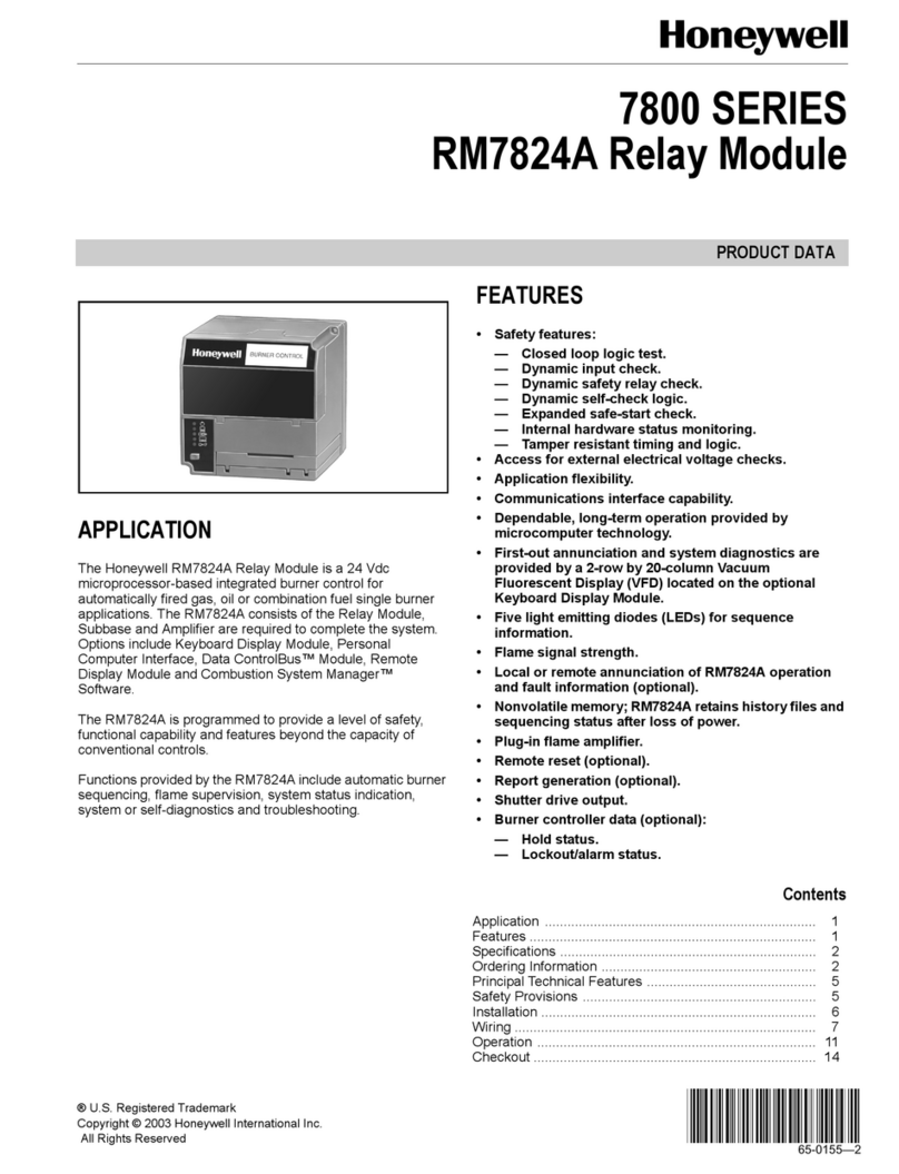
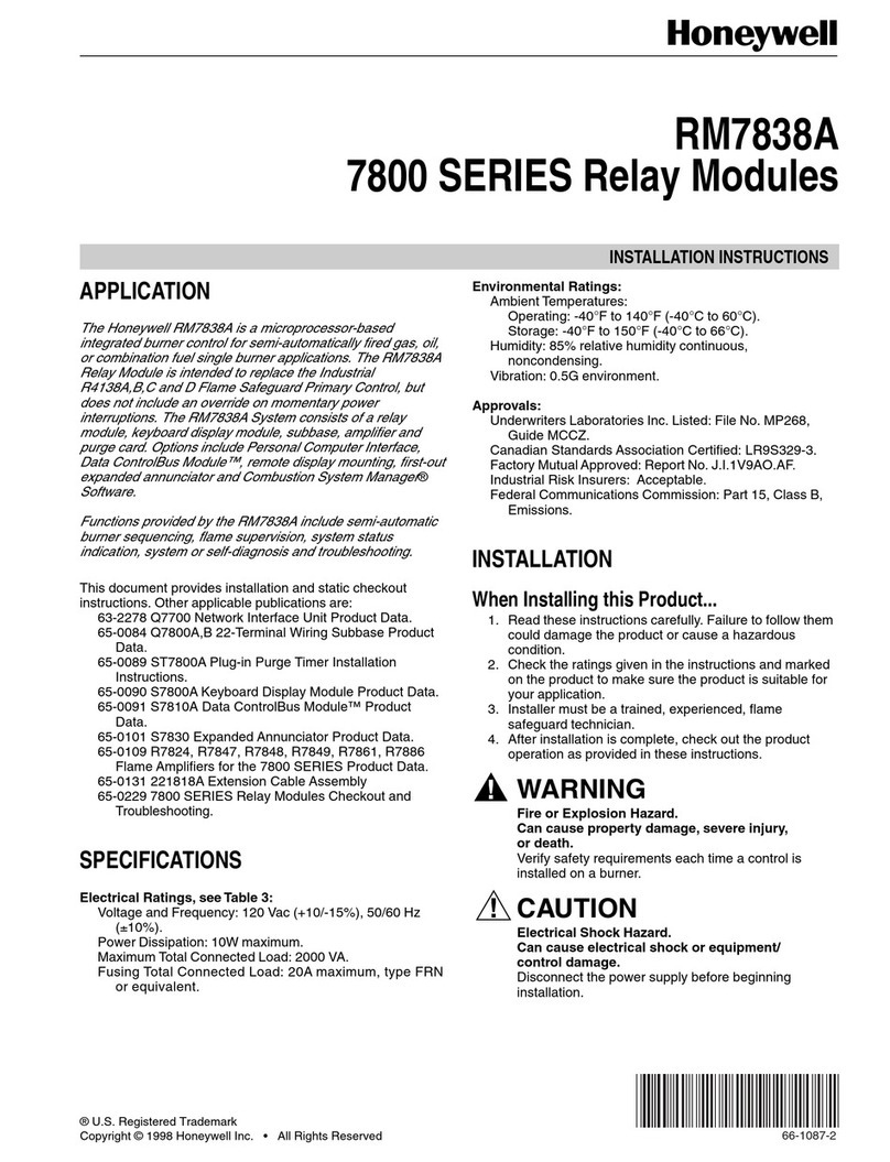
  9. Honeywell SDW 10 Service manual

Honeywell SDW 10 Service manual

® U.S. Registered Trademark EN1H-0222GE51 R0802
Copyright © 2002 Honeywell Inc. • All rights reserved 7157 618
SDW 10
WALL MODULE
MOUNTING AND OPERATING INSTRUCTIONS
GENERAL
The SDW 10 Wall Module can be used for the remote
control of a connected heating circuit. The SDW 10
features the following functions:
•registering the current ambient temperature
(room sensor);
•switching between operating modes
(automatic operation / heating / cooling);
•adjusting the current temperature setpoint
(desired daytime setpoint / setback temperature
setpoint).
temperature setpoint
adjustment knob operating mode
button
Fig. 1. SDW 10 (front view)
Registering the Current Ambient Temperature
The SDW 10's integrated room sensor registers the current
ambient temperature. The resultant value is then employed
for all room temperature-based functions and is also
transmitted to the central system via a double-wire data
bus cable.
Adjusting the Current Temperature Setpoint
Using the temperature setpoint adjustment knob (see Fig.
1), the daytime room temperature setpoint and/or setback
temperature setpoint (defined at the central controller) can
be adjusted by max. ±6 K.
•Rotating the temperature setpoint adjustment knob
clockwise (i.e. towards the symbol) raises the
temperature setpoint.
•Rotating the temperature setpoint adjustment knob
counterclockwise (i.e. towards the symbol) lowers
the temperature setpoint.
Switching between Operating Modes
Using the operating mode button (see Fig. 1), the SDW 10
can be switched from one operating mode to another. This
is done by pushing and holding down the operating mode
button until the desired operating mode is reached (as
indicated by the corresponding LED). It is possible to
switch between the following three operating modes:
The Automatic Operating Mode ( )
In this operating mode, the heating circuit is continuously
controlled in accordance with the programmed time
schedule (P1, P2, or P3) defined at the central controller,
and the temperature setpoint adjustment knob's setting is
taken into account.
The Continuous Heat Operating Mode ( )
In this operating mode, the heating circuit is continuously
controlled in accordance with the daytime room tem-
perature setpoint defined at the central controller, and the
temperature setpoint adjustment knob's setting is taken
into account.
The Continuous Setback Operating Mode ( )
In this operating mode, the heating circuit is continuously
controlled in accordance with the setback temperature
setpoint defined at the central controller, and the
temperature setpoint adjustment knob's setting is taken
into account.
NOTE: The setback temperature setpoint is defined for a
specific heating circuit at the central controller via
the parameter SETBACK OPERATING MODE. It
determines the heating circuit's behavior when in
the continuous setback operating mode. See also
the central controller's Operating Instructions.
Temporary Operating Modes
Temporary operating modes such as PARTY, ABSENT,
and HOLIDAY are indicated as follows:
PARTY: LED flashes ON and OFF continuously.
ABSENT: LED flashes ON and OFF continuously.
HOLIDAY: LED flashes ON and OFF continuously.
Bus Address
In order to restrict communication between the SDW 10
and the central controller to the given heating circuit, each
SDW 10 must be configured to the dedicated heating
circuit. In doing so, an appropriate bus address must be
set. This is done using the rotary HEX code switch (Fig. 2)
accessible after removing the front panel. The bus address
is assigned in accordance with Table 1.
SDW 10 WALL MODULE
Control Products
Honeywell AG
Böblinger Straße 17
D-71101 Schönaich
Phone: (49) 7031 63701
Fax: (49) 7031 637493
http://europe.hbc.honeywell.com
Subject to change without notice. Printed in Germany Manufacturing location certified to
EN1H-0222GE51 R0802
7157 618
Table 1. Bus address assignment
central
controller
SDW 10 bus
address no. bus
address
heating circuit
1 1 10 unmixed heating circuit
2 1 10 mixed heating circuit 1
3 1 10 mixed heating circuit 2
4 2 20 unmixed heating circuit
5 2 20 mixed heating circuit 1
6 2 20 mixed heating circuit 2
7 3 30 unmixed heating circuit
8 3 30 mixed heating circuit 1
9 3 30 mixed heating circuit 2
A 4 40 unmixed heating circuit
B 4 40 mixed heating circuit 1
C 4 40 mixed heating circuit 2
D 5 50 unmixed heating circuit
E 5 50 mixed heating circuit 1
F 5 50 mixed heating circuit 2
0 undefined undefined
IMPORTANT
The assignment of the same bus address to
more than a single SDW 10 will result in
interference during data transmission and thus
controller malfunction.
Incorrect bus address assignment is indicated when
powering up the SDW 10 as follows.
LED: Flashes ON and OFF continuously.
LED and LED: Are lit continuously.
MOUNTING INSTRUCTIONS
Mounting Location
The SDW 10 should be mounted at a location approx. 1.2
to 1.5 meters above floor level at a neutral site
representative, with regards to temperature, for all rooms.
The optimal location is a partition of a room with the
coolest daytime temperature.
The SDW 10 must not be mounted
•at locations exposed to direct sunlight (seasonal
variations should be taken into account);
•close to heat-producing appliances (e.g. televisions,
refrigerators, radiators, etc.);
•on walls heated by under-plaster heating pipes or
chimneys;
•on outside walls;
•in corners behind curtains or shelves (due to
insufficient ventilation);
•close to doors of unheated rooms (due to the influence
of low temperatures);
•on unsealed under-plaster wiring boxes.
Mounting
After removing the front panel, the SDW 10 can be
mounted at the desired location using the accompanying
screws and dowel pins. The cable for the bus connection
must be led through the hole at the bottom of the housing.
Electrical Connection
Electrical connection is effected at the two connection
terminals. Recommended cable: J-Y (ST) Y 2x2x0.6 mm2.
IMPORTANT
Do not reverse the polarity of terminals A and B!
After connecting the data bus cable and selecting the bus
address (see Table 1), replace the front panel.
rotary
HEX
co
d
e sw
i
tc
h
(for setting the bus address)
connection
terminals
F
1
A
2
E
D
C
B
AB
Fig. 2. SDW 10 (with front panel removed)
Common Wiring Scheme
Fig. 3 depicts the connection of one or more SDW 10's
with a central controller.
A B
central controller
data bus
data bus cable (shielded) SDW 10 connected
to heating circuit 1
(direct heating circuit)
additional SDW 10(s)
connected
to heating circuit 2 (3)
(
mixed heatin
g
circuits
)
A B
data bus
SDW 10
A B
data bus
SDW 10
Fig. 3. Connecting to a central controller

Other Honeywell Control Unit manuals

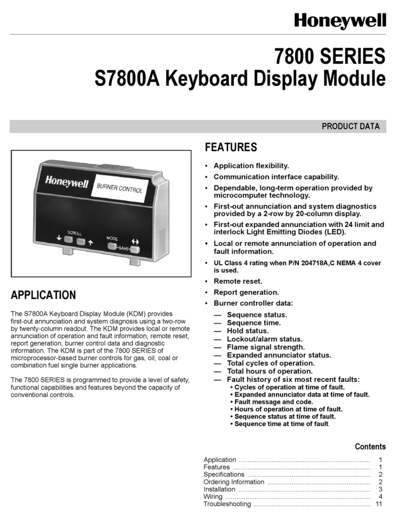
Honeywell S7800A User manual

Honeywell

Honeywell S7800A User manual

Honeywell 7800 SERIES User manual

Honeywell

Honeywell 7800 SERIES User manual

Honeywell VRW2 User manual

Honeywell

Honeywell VRW2 User manual

Honeywell Silent knight 5895XL Operating instructions

Honeywell

Honeywell Silent knight 5895XL Operating instructions

Honeywell VR8205 User manual

Honeywell

Honeywell VR8205 User manual

Honeywell hmr3000 TruePoint User manual

Honeywell

Honeywell hmr3000 TruePoint User manual

Honeywell Silent Knight SK-Monitor User manual

Honeywell

Honeywell Silent Knight SK-Monitor User manual

Honeywell ModBus S7810M User manual

Honeywell

Honeywell ModBus S7810M User manual

Honeywell VP527A User manual

Honeywell

Honeywell VP527A User manual

Honeywell AM-1 Series User manual

Honeywell

Honeywell AM-1 Series User manual

Honeywell VP525C User manual

Honeywell

Honeywell VP525C User manual

Honeywell SOMAT39 User manual

Honeywell

Honeywell SOMAT39 User manual

Honeywell V5055A-E User manual

Honeywell

Honeywell V5055A-E User manual

Honeywell SmartPAC 2 User manual

Honeywell

Honeywell SmartPAC 2 User manual

Honeywell XLS-REL Product manual

Honeywell

Honeywell XLS-REL Product manual

Honeywell 5496 Operating instructions

Honeywell

Honeywell 5496 Operating instructions

Honeywell Krom Schroder PFU 780 Manual

Honeywell

Honeywell Krom Schroder PFU 780 Manual

Honeywell NOTIFIER XP10-M User manual

Honeywell

Honeywell NOTIFIER XP10-M User manual

Honeywell V5004TF User manual

Honeywell

Honeywell V5004TF User manual

Honeywell MAXON 8730 Series User manual

Honeywell

Honeywell MAXON 8730 Series User manual

Honeywell TC810E1040 User manual

Honeywell

Honeywell TC810E1040 User manual

Honeywell SLATE User manual

Honeywell

Honeywell SLATE User manual

Honeywell NK295C User manual

Honeywell

Honeywell NK295C User manual

Honeywell RA116A User manual

Honeywell

Honeywell RA116A User manual

Popular Control Unit manuals by other brands

Samson 2335 Mounting and operating instructions

Samson

Samson 2335 Mounting and operating instructions

Parker VA01 Series manual

Parker

Parker VA01 Series manual

Pepperl+Fuchs ICA-8DIO4M1-G20-IO manual

Pepperl+Fuchs

Pepperl+Fuchs ICA-8DIO4M1-G20-IO manual

AXIOMTEK CEM700 Quick installation guide

AXIOMTEK

AXIOMTEK CEM700 Quick installation guide

Siemens SIMATIC ET 200AL manual

Siemens

Siemens SIMATIC ET 200AL manual

Blood Cells Audio Auscult manual

Blood Cells Audio

Blood Cells Audio Auscult manual

HP HP 81536A user guide

HP

HP HP 81536A user guide

Triax TDH 800 user guide

Triax

Triax TDH 800 user guide

Vag GA Industries FIGURE 927 Installation, operation and maintenance manual

Vag

Vag GA Industries FIGURE 927 Installation, operation and maintenance manual

Senect FILTER CONTROL Series manual

Senect

Senect FILTER CONTROL Series manual

Teleco TVPLI868A01 manual

Teleco

Teleco TVPLI868A01 manual

KSB AMTRONIC R1300 User instructions

KSB

KSB AMTRONIC R1300 User instructions

Siemens SIMATIC FM 456-2 Installation, Hardware, and Startup

Siemens

Siemens SIMATIC FM 456-2 Installation, Hardware, and Startup

Inovance GL20-0800END user guide

Inovance

Inovance GL20-0800END user guide

Parker IOTA ONE Series manual

Parker

Parker IOTA ONE Series manual

Bardiani Valvole GIOTTO TOP Instruction, use and maintenance manual

Bardiani Valvole

Bardiani Valvole GIOTTO TOP Instruction, use and maintenance manual

Rockwell Automation Allen-Bradley 1770-KFC15 user manual

Rockwell Automation

Rockwell Automation Allen-Bradley 1770-KFC15 user manual

PDi BELLA-HD PD295-004 user manual

PDi

PDi BELLA-HD PD295-004 user manual

manuals.online logo
manuals.online logoBrands
  • About & Mission
  • Contact us
  • Privacy Policy
  • Terms and Conditions

Copyright 2025 Manuals.Online. All Rights Reserved.