Wanzl wire tech 100 User manual

Translation of the original operating instructions
Item no. 43.99990.BA-EN07 / 27.09.19
Shopfitting
wire tech 100
Shelving system

Item no. 43.99990.BA-EN07 / 27.09.19
2/36
Table of contents
Table of contents
Table of contents . . . . . . . . . . . . . . . . . . . . . . . . . . . . . . . . . . . . . . . . . . . . . . . . 2
1 Warranty . . . . . . . . . . . . . . . . . . . . . . . . . . . . . . . . . . . . . . . . . . . . . . . . . . . . . 4
2 Safety . . . . . . . . . . . . . . . . . . . . . . . . . . . . . . . . . . . . . . . . . . . . . . . . . . . . . . . 4
2.1 Intended use . . . . . . . . . . . . . . . . . . . . . . . . . . . . . . . . . . . . . . . . . . . . . . . . . . 4
2.2 Areas of use . . . . . . . . . . . . . . . . . . . . . . . . . . . . . . . . . . . . . . . . . . . . . . . . . . 4
2.3 Warnings and safety instructions . . . . . . . . . . . . . . . . . . . . . . . . . . . . . . . . . . . . 5
3 Technical specifications . . . . . . . . . . . . . . . . . . . . . . . . . . . . . . . . . . . . . . . . . . . 7
4 General . . . . . . . . . . . . . . . . . . . . . . . . . . . . . . . . . . . . . . . . . . . . . . . . . . . . . . . 7
4.1 Description in these operating instructions . . . . . . . . . . . . . . . . . . . . . . . . . . . . . 7
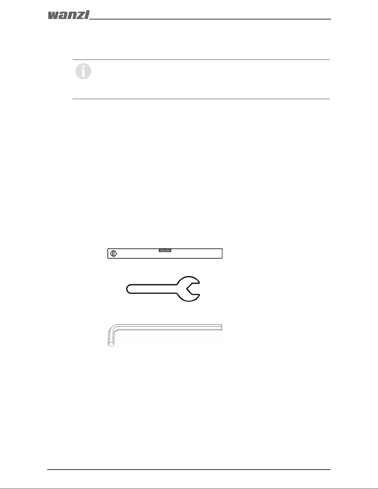
4.2 Tools required . . . . . . . . . . . . . . . . . . . . . . . . . . . . . . . . . . . . . . . . . . . . . . . . . 7
5 Shelving systems with two uprights and one back panel . . . . . . . . . . . . . . . . . . . . . 8
5.1 View . . . . . . . . . . . . . . . . . . . . . . . . . . . . . . . . . . . . . . . . . . . . . . . . . . . . . . . 8
5.2 Installation instructions . . . . . . . . . . . . . . . . . . . . . . . . . . . . . . . . . . . . . . . . . . 9
5.2.1 Uprights . . . . . . . . . . . . . . . . . . . . . . . . . . . . . . . . . . . . . . . . . . . . . . . . . . . 9
5.2.2 Position of Wanzl logo . . . . . . . . . . . . . . . . . . . . . . . . . . . . . . . . . . . . . . . . . 10
5.3 Installing the basic shelving unit . . . . . . . . . . . . . . . . . . . . . . . . . . . . . . . . . . . 11
5.3.1 Removing the lattice back panel with an extraction tool . . . . . . . . . . . . . . . . . 12
5.4 Further back panels . . . . . . . . . . . . . . . . . . . . . . . . . . . . . . . . . . . . . . . . . . . . 13
5.4.1 Installing the reinforced lattice back panel . . . . . . . . . . . . . . . . . . . . . . . . . . . 13
5.4.2 Installing a blister back panel . . . . . . . . . . . . . . . . . . . . . . . . . . . . . . . . . . . . 14
5.4.3 Installing an 8 mm / 0.3 in back panel and 19 mm / 0.8 in back panel . . . . . . . . 15
5.4.4 Installing a metal back panel . . . . . . . . . . . . . . . . . . . . . . . . . . . . . . . . . . . . 16
5.5 Installing the plinth cover . . . . . . . . . . . . . . . . . . . . . . . . . . . . . . . . . . . . . . . . 17
5.6 Installing the base metal shelf . . . . . . . . . . . . . . . . . . . . . . . . . . . . . . . . . . . . . 17
5.7 Installing a reinforcing foot for the base metal shelf . . . . . . . . . . . . . . . . . . . . . . 18
5.8 Installing the base front grid . . . . . . . . . . . . . . . . . . . . . . . . . . . . . . . . . . . . . . 19
5.9 Installing a cover . . . . . . . . . . . . . . . . . . . . . . . . . . . . . . . . . . . . . . . . . . . . . . 19
5.10 Installing an upright extension . . . . . . . . . . . . . . . . . . . . . . . . . . . . . . . . . . . . . 19
5.11 Installing the support tube . . . . . . . . . . . . . . . . . . . . . . . . . . . . . . . . . . . . . . . 20
5.12 Installing a double bracket . . . . . . . . . . . . . . . . . . . . . . . . . . . . . . . . . . . . . . . 21
5.13 Installing a shelf . . . . . . . . . . . . . . . . . . . . . . . . . . . . . . . . . . . . . . . . . . . . . . 22
5.13.1 Installation instructions . . . . . . . . . . . . . . . . . . . . . . . . . . . . . . . . . . . . . . . . 22
5.13.2 Shelf pre-assembly . . . . . . . . . . . . . . . . . . . . . . . . . . . . . . . . . . . . . . . . . . . 22
5.13.3 Installing the shelves on the uprights . . . . . . . . . . . . . . . . . . . . . . . . . . . . . . . 23
5.13.4 Installing the reinforcing C-profile . . . . . . . . . . . . . . . . . . . . . . . . . . . . . . . . . 23
5.13.5 Console screw connections . . . . . . . . . . . . . . . . . . . . . . . . . . . . . . . . . . . . . 24
5.13.6 Installing the front bracket for wire shelves . . . . . . . . . . . . . . . . . . . . . . . . . . 25
5.13.7 Installing a shelf separating grid . . . . . . . . . . . . . . . . . . . . . . . . . . . . . . . . . . 25
5.13.8 Installing a hanging basket . . . . . . . . . . . . . . . . . . . . . . . . . . . . . . . . . . . . . . 26
5.13.9 Installing a universal adapter . . . . . . . . . . . . . . . . . . . . . . . . . . . . . . . . . . . . 27
5.13.10 Installing a metal shelf . . . . . . . . . . . . . . . . . . . . . . . . . . . . . . . . . . . . . . . . . 27
5.14 Installing the information sign holder . . . . . . . . . . . . . . . . . . . . . . . . . . . . . . . . 28
6 Installing a wall attachment . . . . . . . . . . . . . . . . . . . . . . . . . . . . . . . . . . . . . . . . 29
6.1 Wall attachment . . . . . . . . . . . . . . . . . . . . . . . . . . . . . . . . . . . . . . . . . . . . . . 29
6.2 Adjustable wall attachment . . . . . . . . . . . . . . . . . . . . . . . . . . . . . . . . . . . . . . 30

Item no. 43.99990.BA-EN07 / 27.09.19 3/36
Table of contents
7 Load chart . . . . . . . . . . . . . . . . . . . . . . . . . . . . . . . . . . . . . . . . . . . . . . . . . . . 31
7.1 Permissible shelf load per shelf axis . . . . . . . . . . . . . . . . . . . . . . . . . . . . . . . . . 31
7.1.1 Permissible load for individual shelves on the console . . . . . . . . . . . . . . . . . . . 31
7.1.2 Permissible load for base shelf . . . . . . . . . . . . . . . . . . . . . . . . . . . . . . . . . . . 31
7.1.3 Calculation of the permissible load of a wall-mounted shelving unit . . . . . . . . . . 32
7.1.4 Example calculations . . . . . . . . . . . . . . . . . . . . . . . . . . . . . . . . . . . . . . . . . . 33
7.1.5 With support upright . . . . . . . . . . . . . . . . . . . . . . . . . . . . . . . . . . . . . . . . . . 34
8 Cleaning instructions . . . . . . . . . . . . . . . . . . . . . . . . . . . . . . . . . . . . . . . . . . . . 36

Item no. 43.99990.BA-EN07 / 27.09.19
4/36
Warranty
1Warranty
Every Wanzl product undergoes a thorough final in-house check.
Any complaints that may arise despite these precautions are handled by Wanzl as follows:
Any defects which occur within 12 months of the date of delivery (or another contractually
determined warranty period) will be rectified by Wanzl free of charge, provided that these
defects can be proved to be due to faults in the materials or manufacture.
The warranty does not extend to parts with restricted service life such as light barriers,
for example. The warranty period for rechargeable batteries is 6 months.
In carrying out repairs covered by the warranty, Wanzl is responsible for all material, assembly,
travel and transport costs. No additional claims will be honored.
The 12-month warranty period (or another contractually determined warranty period) begins
on the date of delivery or date of assembly by Wanzl technicians or by specialists authorized
by Wanzl.
Defective parts that have been replaced become the property of Wanzl.
The full warranty only applies provided that assembly, service and repairs were carried out
by Wanzl technicians or specialists authorized by Wanzl.
The warranty is not valid for damage that results from inappropriate use or external causes.
Warranty claims are rendered invalid if Wanzl does not receive written notice within 14 days
of the defect becoming apparent. This notice must include the project and order number and
a specific description of the defect.
The warranty period does not recommence following work carried out under the warranty.
Wanzl extends the warranty for an additional 12 months (or other contractually determined
warranty period) for replacement parts.
Warranty claims expire 12 months (or another contractually determined warranty period)
after receipt of the written notification at Wanzl.
2 Safety
2.1 Intended use
•Shelving system for the presentation and sale of food and non-food items in the commercial
sector.
•Depending on the version, the shelving system described is intended for:
– Wall installation (with L-uprights)
– Gondola solution (shelving unit in the middle of the space and accessible from all sides).
2.2 Areas of use
•To only be used indoors or in external areas protected from adverse weather on a firm,
even and level surface!
•Observe local construction and safety regulations as well as specifications set out
by health authorities and regulatory agencies.
Read these instructions carefully before assembly and commissioning.
Keep this manual for future use.

Item no. 43.99990.BA-EN07 / 27.09.19 5/36
Safety
2.3 Warnings and safety instructions
WARNING! The product may tip or break if loaded unevenly, overloaded or used
improperly.
The result: Breakage of the product and risk of injury to persons and/or damage
to property.
►Only place the product on a firm, even and level surface.
►Ensure that the existing floor is able to support the surface pressure exerted by the
product.
►Use fastening material that is appropriate for the walls.
►Use longer screws and spacer sleeves for deeper-seated concrete layers.
►Only load the product evenly, not just on one side.
►Do not overload the product.
►Only use the product as intended.
►Do not continue to use a defective product. If necessary, have it repaired.
►Ensure that there is no danger or risk of injury to persons.
WARNING! If using a top frame or gondola end shelf, the product may tip or break if load-
ed haphazardly.
The result: breakage of the product and risk of injury to persons and/or damage
to property.
►Always load the gondola axis first and only then the shelves of the top frame or end
shelves.
►First empty the shelf at the top frame or end shelves and then the gondola axis.
►A load >the total load of the loaded shelves of the top frame or end shelves must be
applied in the gondola axis (equilibrium).
WARNING! There is a risk of injury when installing or setting up the product.
The result: injury to hands or feet due to crushing or shearing.
►Note the risk of injury to hands and feet when installing or setting up the product.
►Only have the product installed by trained and qualified staff.
►Install the shelving system with the assistance of a second person.
►
Be aware of the risk of injuries from parts that may tip over during the installation
.
►Wear safety gloves during the installation.
►Wear safety goggles during drilling work.

Item no. 43.99990.BA-EN07 / 27.09.19
6/36
Safety
• Observe the installation instructions that follow.
• Unload the shelving system before transporting it to another location.
• Only transport the dismantled shelving system.
• Only use genuine Wanzl spare parts.
• Regularly carry out and keep records of maintenance work.
• Only use specialist Wanzl technicians or companies authorized by Wanzl to carry out
maintenance and repair work.
WARNING! If the product is overloaded or if persons pull on or suspend things from the
product, it may tip or break.
The result: Tipping over or breakage of the product and risk of injury to persons and/or
damage to property.
►Please note that no-one, especially children, should hang on the product or climb on it.
►As the operator of the store, secure the stored goods so that the stored goods are se-
cured against falling down.
►Secure the shelving system to be installed on the wall against tipping over by means
of a wall attachment (see Chapter 6).
►Ensure that no one stands in or on the product.
►Ensure that no one stands on the guide rail.
DANGER! When retrofitting lighting fixtures, the shelving system is supplied with mains
voltage which is dangerous to touch.
There is a risk to life in the event of improper installation or damaged lights.
The result: People may be endangered and injured or even killed.
►When working with the lighting fixtures or in the event of a defective lighting fixture,
disconnect the mains plug of the power supply cable or switch the mains voltage off
and secure it against being switched on again.
►Fit the power supply cable such that it does not pose a tripping hazard.
►Only connect the light element to a power socket with earthing contact
or a connection with protective earthing.
►Only use lighting retrofit kits approved by Wanzl.
►Ensure that the electric installation is only carried out and regularly checked by Wanzl
technicians or companies authorized by Wanzl.
►Wanzl accepts no liability for installations of light fixtures by companies not authorized
by Wanzl.

Item no. 43.99990.BA-EN07 / 27.09.19 7/36
Technical specifications
3 Technical specifications
4 General
4.1 Description in these operating instructions
• The wire tech 100 shelving system is available in many variants and sizes.
• These operating instructions describe the basic structure of the shelving system.
• The installation steps shown in the installation sections only represent one example
of the installation.
• Further installation instructions, which must be additionally observed, are available
for special solutions and customer-specific variants.
4.2 Tools required
Please see the Technical Description for the views, dimensions and order numbers
for the individual components.
For further technical information, please contact Technibilt’s Shopfitting department
at 1-800-351-2278 ext 2534.
The address can be found on the last page of these instructions.
spirit level
SW 17 spanner tool
for adjustable feet
Gr. 5 Allen key
Tool for 180° end element
and guide tube

Item no. 43.99990.BA-EN07 / 27.09.19
8/36
Shelving systems with two uprights and one back panel
5
Shelving systems with two uprights and one back panel
5.1 View
Fig. 1
Item Name Item Name
1 L-upright or T-upright 8 Base metal shelf
2 Lattice back panel 9 Front panel
3 Adjustable foot 10 Base cover
4 Cover 11 Shelf front grid
5 Bracket 12 Shelf separating grid
6 Console 13 Type plate
7 Wire shelf

Item no. 43.99990.BA-EN07 / 27.09.19 9/36
Shelving systems with two uprights and one back panel
5.2 Installation instructions
5.2.1 Uprights
• From a shelf height of 2,240 mm / 88 in, a
wall bracket is necessary without increas-
ing the shelf load.
• Top shelf max. 1,900 mm / 74 in height,
otherwise wall attachment is required.
• The shelf load should decrease the higher
the shelf (see Chapter 7.1.3).
• The shelf depth should be the same or
it should decrease the higher the shelf.
• The shelf height to depth ratio may not
exceed 5:1, otherwise wall attachment
is necessary.
• Max. shelf depth = base depth.
• No suspensions are allowed at the rear
of the wall-mounted shelf.
• Mount the type plate at the beginning and
end of each wall or gondola unit.
• Special requirements may only be arranged
after consultation; written approval is
necessary.
Fig. 2
Fig. 3 If the loads are higher, reinforced uprights must be used.

Item no. 43.99990.BA-EN07 / 27.09.19
10/36
Shelving systems with two uprights and one back panel
5.2.2 Position of Wanzl logo
Fig. 4
The Wanzl logo must be applied to the product! Please see below for the positions.
Thoroughly clean the surface to be glued beforehand (so it is free of grease and dust)!

Item no. 43.99990.BA-EN07 / 27.09.19 11/36
Shelving systems with two uprights and one back panel
5.3 Installing the basic shelving unit
The installation of the lattice back panel is shown in Fig. 5 and Fig. 6 with
two L-uprights. T-uprights are shown in the remainder of the instructions.
Fig. 5
Fig. 6
►To prevent the lattice back panel from lifting out of the top upright slot, insert a bracket
above and a bracket below the cross wire (X).
►Check to ensure that the brackets are firmly seated and correctly installed, e.g. by briefly
pulling on the back panel. The brackets must not come out of the upright.

Item no. 43.99990.BA-EN07 / 27.09.19
12/36
Shelving systems with two uprights and one back panel
5.3.1 Removing the lattice back panel with an extraction tool
Fig. 7 Fig. 8
►Rotate the adjustable foot outwards
by maximum 25 mm / 1 in.
Fig. 9 Fig. 10

Item no. 43.99990.BA-EN07 / 27.09.19 13/36
Shelving systems with two uprights and one back panel
5.4 Further back panels
5.4.1 Installing the reinforced lattice back panel
A reinforced lattice back panel must be inserted in every first axis after a 180°
end element or top frame.
Fig. 11 A = Bracket
Fig. 12 A=Bracket, B=Hook

Item no. 43.99990.BA-EN07 / 27.09.19
14/36
Shelving systems with two uprights and one back panel
5.4.2 Installing a blister back panel
Fig. 13 Fig. 14
Fig. 15 Fig. 16

Item no. 43.99990.BA-EN07 / 27.09.19 15/36
Shelving systems with two uprights and one back panel
5.4.3 Installing an 8 mm / 0.3 in back panel and 19 mm / 0.8 in back panel
Fig. 17
►Press the cross-connector together at
the open end and hang it into the slot
of the upright.
Fig. 18
Fig. 19
►Insert the U-profile from above until
it snaps into the upright.
Fig. 20

Item no. 43.99990.BA-EN07 / 27.09.19
16/36
Shelving systems with two uprights and one back panel
5.4.4 Installing a metal back panel
Fig. 21
Fig. 22
►Hang fixing plates on both sides to
prevent the wood back panel from
being pushed through.
– Note: no fixing plates are required for
the 19 mm / 0.8 in wood back panel.
Fig. 23 X = Fixing plates
Fig. 24 Fig. 25

Item no. 43.99990.BA-EN07 / 27.09.19 17/36
Shelving systems with two uprights and one back panel
5.5 Installing the plinth cover
5.6 Installing the base metal shelf
Fig. 26 Fig. 27
Fig. 28 Fig. 29
Fig. 30
Fig. 31

Item no. 43.99990.BA-EN07 / 27.09.19
18/36
Shelving systems with two uprights and one back panel
5.7 Installing a reinforcing foot for the base metal shelf
Fig. 32 Fig. 33
Fig. 34 Fig. 35
Fig. 36 Fig. 37

Item no. 43.99990.BA-EN07 / 27.09.19 19/36
Shelving systems with two uprights and one back panel
5.8 Installing the base front grid
5.9 Installing a cover
5.10 Installing an upright extension
Fig. 38 Fig. 39
Fig. 40 Fig. 41
The purpose of the upright extension is only to attach decorations!
Fig. 42 Fig. 43

Item no. 43.99990.BA-EN07 / 27.09.19
20/36
Shelving systems with two uprights and one back panel
5.11 Installing the support tube
Fig. 44 Fig. 45
Fig. 46 Fig. 47
Fig. 48 Fig. 49
Table of contents
Popular Commercial Food Equipment manuals by other brands

KoolMore
KoolMore Commercial 24x30 Assembly instructions

Hussmann
Hussmann RFLNS Installation & operation manual

Fri-Jado
Fri-Jado TDR auto-clean Service manual

croydon
croydon MPE-200001 W4 instruction manual

Marshall Amplification
Marshall Amplification DH5E-3 Series owner's manual

Bourgeat
Bourgeat NOMAD Instructions for use and maintenance

STODDART
STODDART Culinaire CH.BM.U Specification, installation and operation manual

Bourgeat
Bourgeat HARMONIE Series Instructions for use and maintenance

Groen
Groen DH-20C Operator's manual

Cres Cor
Cres Cor H138NPSCMQ Series Operating and maintenance instructions

MINERVA OMEGA
MINERVA OMEGA C/E 652 operating instructions

Fri-Jado
Fri-Jado Hot CC user manual