Ward-Beck Systems AMS81 User manual

AMS81
8 CHANNEL AUDIO MONITORING SYSTEM
by Ward-Beck Systems
Rev:Oct.01 2014

AMS81 (version 2.1.1.7 and above)
Carefully unpack your AMS81 and make sure that damage has not occurred during
shipping. The unit should be ready for use as soon as it is plugged in to the AC
power source and a signal is connected to it.
Please note:
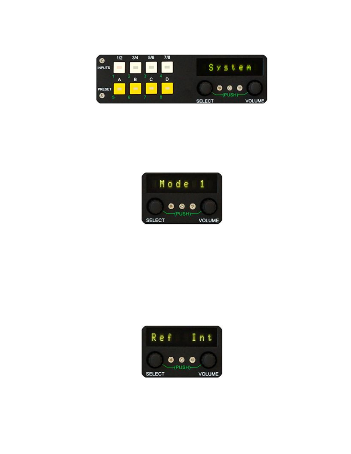
The default MODE setting for a unit that includes a Dolby Decoder is MODE 1 in
this mode inputs may be a mix of Dolby E, Dolby AC-3 or PCM and it is
recommended that the unit be operated in this mode only.
The default mode for units without a Dolby Decoder is MODE 2. In this mode
inputs can only be PCM and the unit should only be operated in this mode.
MODE 4 is a task specific application that may be used when the unit is equipped
with a Dolby Decoder. Please refer to the set up for MODE 4 in this manual.
An optional DEMUXER may be installed in your AMS8. This increases the input
capability of your unit. The DEMUXER is capable of extracting all embedded
groups (a maximum of eight AES signal pairs) from each of the two digital video
signals.
FRONT PANEL DISPLAYS AND CONTROLS
Please note that primary functions for controls are designated in white, while
secondary functions are designated in green.
FRONT PANEL DISPLAYS
Eight 22 segment LED bar graph meters display VU and Peak Program information
simultaneously. A reference LED (red) at the zero mark is continuously illuminated.
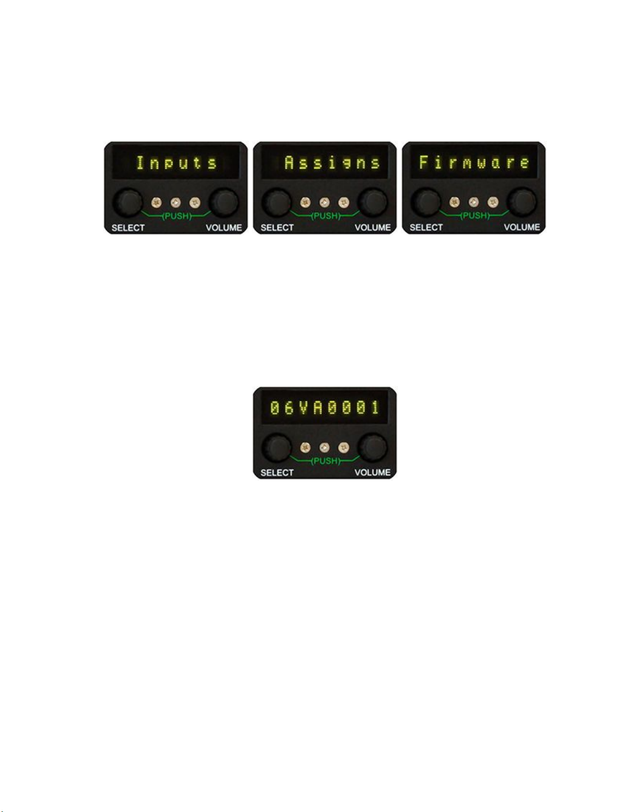
An eight-character dot-matrix display located above the SELECT and VOLUME
controls display signal parameters and status information. During setup, this
display is used to guide the user in making selections.

FRONT PANEL CONTROLS
There are eight illuminated push button switches arranged in two rows of four. The
upper row designated INPUTS selects the input source to be monitored. The lower
row designated PRESETS selects a preset configuration or condition under which
the signal is monitored.
The two control knobs designated SELECT and VOLUME are rotary shaft encoders
with integral push switches. In the simplest mode of operation, the SELECT knob
allows the user to scroll through available options while the VOLUME button adjusts
the listening level of the AMS8's speakers.
All eight push buttons, as well as the two knobs with integral push switches, are
used in conjunction with the eight-segment read out when the unit is configured
during SYSTEM SETUP.

SYSTEM SETUP
To enter system setup, press and hold INPUT buttons 1/2 and 7/8 with one hand
and press the SELECT knob. The readout will display System. Press the SELECT
button again to enter the mode of operation selection. The readout will display
Mode X, where X is 1, 2, or 4.
The VOLUME knob may be rotated, in either direction, to select the appropriate
mode of operation.
Rotate the SELECT knob one step clockwise to enter the reference signal setup.
The readout will display Ref above the SELECT knob and Int, 75Ωor 110Ωabove
the VOLUME knob.
Ref Int - means that the internal 48 kHz reference is used
Ref 75Ω - means that an external unbalanced reference will be used
Ref 110Ω - means that an external balanced reference will be used
Rotating the VOLUME knob in either direction selects the appropriate reference
source.

Rotate the SELECT knob another step clockwise to enter the AES OUTPUT #4
Setup. The readout will display Out4 above the SELECT knob and In4 or Mon
above the VOLUME knob.
Out4 In4- means that AES input #4 will be routed to AES output #4.
Out4 Mon - means that the Monitor Output will be routed to AES output #4.
Rotate the SELECT knob another step clockwise to enter the Dialogue
Normalization setup. The readout will display Dn above the SELECT knob and
Enbd or Dsbd above the VOLUME knob.
Dn Enbd - means that the dialogue normalization level in the metadata will be
applied to the dolby signal.
Dn Dsbd - means that the dialogue normalization level in the metadata will not be
applied to the dolby signal.
Rotate the SELECT knob another step clockwise. The readout will display Vol over
the SELECT knob and a default volume level reading between OFF, -60db and
+15dB above the VOLUME knob.
The VOLUME control is used to set the default volume level, in one dB steps, for
monitoring audio.

Rotate the SELECT knob another step clockwise. The readout will display O/P
above the SELECT knob and either Var or Fix above the VOLUME knob. Rotating
the VOLUME knob in either direction will toggle between Var and Fix.
O/P Var - means that all the outputs of the unit will be level controlled and follow the
action of the VOLUME control
O/P Fix - means that all the outputs will be a fixed line level (-20 dBFs for digital
outputs and +4dBu for analog outputs) the VOLUME control will only affect the level
of the internal speakers and also the two monitor outputs on the back of the unit.
Rotate the SELECT knob another step clockwise. The readout will display Cal over
the SELECT knob and a reference level reading between -22dB and -10dB above
the VOLUME knob.
The VOLUME control is used to set the reference level, in two dB steps, for
monitoring audio.

Rotate the SELECT knob one more step clockwise. The readout will display Spkr
above the SELECT knob and either On or Off above the VOLUME knob. Rotating
the VOLUME knob in either direction will toggle between On and Off.
(In Version 1.x.x.x.)
Spkr On means the internal speakers and headset jack are enabled, and enables
monitor output.
Spkr Off means the internal speakers and headset jack are disabled, and disables
the monitor output.
(In Version 2.x.x.x. and above)
Spkr On means the internal speakers and headset jack are enabled.
Spkr Off means the internal speakers and headset jack are disabled.
Rotate the SELECT knob one more step. The readout now displays Exit.
Push the SELECT knob to return to the System setup screen. To exit system
setup, turn the SELECT knob one step counter clockwise. The readout displays
Exit. Push the SELECT knob once to exit the system setup procedures.

CHECKING THE FIRMWARE
When the system setup mode has been activated and the readout displays
System, rotating the SELECT knob clockwise will cycle through the following:
Inputs
- This configuration setup allows you to select the input sources that will be
enable during monitoring. (See INPUTS SETUP).
Assigns - This configuration setup applies only to units set to operate in Mode 1.
(See ASSIGNMENT SETUP).
Firmware - This allows you to check the version of firmware installed in your unit.
Press the SELECT knob once and a numeric code will be displayed in the readout
window, such as 2.0.0.0. This is the firmware version identifier and is information
that will be helpful if you contact the factory for technical assistance.
To exit the firmware interrogation mode, rotate the SELECT knob one step counter
clockwise and push the SELECT knob once when the readout displays Exit.

INPUTS SETUP (for all modes)
A fully assembled AMS8 has multiple program inputs (75Ω, 110Ω, Analog, SDI 1
(A) Groups 1 and 2, SDI 1 (A) Groups 3 and 4 and SD1 2 (B) Groups 1 and 2 and
SDI 2 (B) Groups 3 and 4. The Inputs setup allows an operator to enable or disable
the input option during monitoring. When the System Setup mode has been
activated and the readout displays System, rotating the SELECT knob clockwise
one step will put the unit in the Inputs mode. Press the SELECT knob once and the
75Ωoption will be displayed in the readout window above the SELECT knob. The
display above the VOLUME knob will indicate whether the Input option is enabled.
If (Y) is displayed then the Input option is enabled. If (N) is displayed then the input
option is disabled. Rotate the SELECT to cycle through the remaining input
options. To save the settings Rotate the SELECT knob until the readout displays
Exit and press the SELECT knob once. This will bring you back to the System
Setup mode.
(In Version 1.x.x.x. and above)
Enable SDI 1/2 for SDI Groups 1 and 2
Enable SDI 3/4 for SDI Groups 3 and 4
(In Version 06VA0001 and above)
Enable SDI 1/2 for SDI 1 (A) Groups 1 and 2
Enable SDI 3/4 for SDI 1 (A) Groups 3 and 4
Enable SDI 5/6 for SDI 2 (B) Groups 1 and 2
Enable SDI 7/8 for SDI 2 (B) Groups 3 and 4

ASSIGNMENT SETUP (for Mode 1 only)
The AMS8 has the ability to monitor multiple inputs, IN1 to IN4 at 75Ω, 110Ωand
Analog, as well as, eight digital programs within one of the two SDI streams. The
Assigns setup allows an operator to assign any one of these inputs to the four
INPUT select pushbutton switches for rapid selection. In the Assigns setup
procedure, A1 is the 1/2 button, A2 is the 3/4 button, A3 is the 5/6 button and A4 is
the 7/8 button.
When the system setup mode has been activated and the readout displays
System, rotating the SELECT knob clockwise one step will put the units in the
Assigns mode. Press the SELECT knob once and the first assignment A1 will be
displayed in the readout window above the SELECT knob. The display above the
VOLUME knob will indicate which source is assigned to A1 or the 1/2 INPUTS
button.
Rotate the VOLUME knob in either direction to select the desired input 75 -1 to 4,
110 -1 to 4, ANL -1 to 4, SD1 -1 to 8and SD2 -1 to 8to assign A1. Rotate the
SELECT knob through A2, A3 and A4 and similarly assign an input source.
NOTE: It is possible to assign the same source to more than one button.
To exit and return to the System Setup mode turn the SELECT knob in either
direction until Exit is displayed in the readout then push the Select knob.

CONFIGURING A PRESET
(Presets can only be configured when operating in MODE 2)
Press and hold a PRESETS button for approximately three seconds.
If preset button A is selected, the readout should display A L1 above the SELECT
knob and either Off or a level between -15 and +15 above the VOLUME knob.
Rotating the SELECT knob in either direction cycles through the eight available
sources that are displayed on the LED meters.
The numbers L1 through L8 correspond to the green numbers 1 through 8 below
the INPUTS and PRESETS buttons that are assigned to the left channel of the
monitor. To assign a source to a preset, rotate the SELECT knob until the source
number and status appears in the readout window, and then push the
corresponding numbered button. The button will illuminate to indicate that it has
been assigned. To remove a source, push the illuminated button. The button LED
will extinguish.
When a source is assigned, the Off display above the VOLUME knob will change to
0. This means that the signal is assigned at nominal level.
The level can be adjusted for that signal by +/- 15dB by rotating the VOLUME knob
clockwise or counter clockwise. The amount of gain or loss from nominal for the
selected signal will be displayed above VOLUME knob in a range from -15 to +15.
Once all the sources are assigned and the mix set for L1, the left channel, push the
select knob once to enter the setup for R1, the right channel. Follow procedures as
described above for the left channel. Once all the sources are assigned and the mix
set for R1, the right channel, push the select knob once to exit the Preset Setup
mode. The preset Aswitch will be illuminated to indicate that preset Ais active. To
return to normal operation press the preset Aswitch once. Repeat the above
procedures for PRESETS B, C, and D.

OPERATING IN MODE 1 (Default for units with Dolby Decoder installed)
The AMS8 would be set to operate in Mode 1 when dealing with multiple channels
PCM or Dolby digital signals. A Dolby decoder must be installed in the unit. Input
sources can be either PCM, Dolby AC-3 or Dolby E.
In Mode 1, a source selection is made by pressing any one of the four INPUTS
select pushbuttons. The INPUTS select pushbuttons can be assigned to select any
one of the unbalanced, 75 Ohm sources, any one of the balanced 110 Ohm
sources or any of the four Assigns, A1 to A4.
Push and simultaneously turn the SELECT knob to cycle through 75ΩLoRo,
110ΩLoRo or the A1 - 4 assigns. If the Analog and/or Demux boards are available
Analog, SDI 1/2, SDI 3/4, SDI 5/6 and SDI 7/8 can also be accessed.
For example, pressing the 1/2 button displays A1 75-3. This means that the third
unbalanced source was assigned to 1 / 2 button and has now been selected. If the
readout displays 75ΩLoRo, it means that unbalanced input #1 is selected. If the
readout displays 110ΩLoRo, it means balanced input #1 is selected.
NOTE: If the signal is not present or corrupted, the readout will indicate No Lock.
If a signal is present, it will be identified, and the type of signal displayed in the
readout window. (There is a slight lag while the processor determines the signal
status.)
Please refer to the DATA TABLE for the Dolby signal configurations.
If the source is a PCM signal, the level will always be displayed on the CH1 and
CH2 LED meters. To increase or decrease the listening level, rotate the VOLUME
knob clockwise or counter clockwise. As soon as the VOLUME control is rotated,
the gain/loss in dB is displayed in the read out window. The range is from OFF, -60
dB to +15dB. The speakers and the two monitor outputs on the back of the unit
may also be muted by pressing the VOLUME knob, in which case the readout will

display Mute.
The two channel PCM signal may also be converted to a ProLogic Surround
version by rotating the SELECT knob in either direction. The readout will display
PCM /PL.
The ProLogic signal comprises Left, Right, Centre, Left rear and Right rear. These
signal levels are displayed on the CH1, CH2, CH3, CH5 and CH6 LED bar graphs
respectively. To return to the PCM mode, rotate the SELECT knob in either
direction.
A copy of the signal that is displayed on the LED bar graph will also appear on the
output connectors on the rear of the unit, paired as a discrete AES digital signal.
CH1 and 2 on output #1
CH3 and 4 on output #2 (no program, LFE, on CH4)
CH5 and 6 on output #3
CH7 and 8 on output #4 (no program)
If the source is a Dolby digital signal (AC-3 or E) it will be processed, displayed and
assigned to the discrete AES output as follows:
SIGNAL
OUTPUT#
METER
L (left )
1 (A channel)
CH1
R (right)
1 (B channel)
CH2
C (centre)
2 (A channel)
CH3
LFE (low freq.)
2 (B channel)
CH4
Ls (left surround)
3 (A channel)
CH5
Rs (right surround)
3 (B channel)
CH6
Aux audio
4 (A channel)
CH7
Aux audio
4 (B channel)
CH8

If the signal is lost through interruption or if an internal error occurs and the unit
cannot lock to the incoming signal, the readout will indicate No Lock.
The four PRESETS pushbuttons may be used to listen to the signals solo,
discretely or summed (for phase checking). Button Aselects channels 1 and 2,
button Bselects channels 3 and 4, button Cselects channels 5 and 6 and button D
selects channels 7 and 8.
Pushing the A PRESETS button repeatedly cycles through:
In 1 Ch 1 Signal displayed on CH1 meter is fed to all speakers of the
AMS8
In 1 Ch 2 Signal displayed on CH2 meter is fed to all speakers of the
AMS8
In 1 1 / 2 CH1 and CH2 meter signals are fed to the left and right
speakers respectively
In 1 1 + 2 The summed result of the CH1 and 2 mix is fed to all speakers
In 1 LoRo The left and right overall signal is fed to the left and right
speakers respectively
Buttons B, C and D repeat the process for channels 3 / 4, 5 / 6 and 7 / 8.

OPERATING IN MODE 2
In Mode 2, the AMS8 operates as a multi-channel monitor box with the ability to
proportionally mix any of the inputs to the left and right monitor channels. All inputs
must be PCM. The unit will accept eight inputs; four unbalanced and four balanced
sources.
The LED bar graph meters will display the signals consequentially. Input #1 will be
selected by the 1/2 INPUTS button and will be displayed on CH1 and CH2. Input
#2 will be selected by the 3/4 INPUTS button and will be displayed on CH3 and
CH4. Input #3 will be selected by the 5/6 INPUTS button and will be displayed on
CH5 and CH6. Input #4 will be selected by the 7/8 INPUTS button and will be
displayed on CH7 and CH8.
MAKING A SOURCE SELECTION
Press the appropriate INPUTS button. The readout will display 75ΩL/R or 110Ω
L/R.
If the unit displays 75ΩL/R, it means that the bank of four unbalanced inputs is
selected. If the unit displays 110ΩL/R, it means that the bank of balanced inputs is
selected. To toggle between the two banks of inputs, press and rotate the SELECT
knob.
If the Analog and/or Demux boards are available Analog,SDI 1/2,SDI 3/4,SDI 5/6
and SDI 7/8 can also be accessed.
To select a preset mix, press any one of the four PRESETS buttons A, B, C or D.
(In Version 1.x.x.x. and above)
Select SDI 1/2 for SDI Groups 1 and 2
Select SDI 3/4 for SDI Groups 3 and 4
(In Version 06VA0001 and above)

Select SDI 1/2 for SDI 1 (A) Groups 1 and 2
Select SDI 3/4 for SDI 1 (A) Groups 3 and 4
Select SDI 5/6 for SDI 2 (B) Groups 1 and 2
Select SDI 7/8 for SDI 2 (B) Groups 3 and 4

OPERATING IN MODE 4
The AMS8 would be set to operate in Mode 4 for a task specific application. In
Mode 4, the types of signals that can be connected to the input source connectors
are strictly defined. Inputs 1, 2 and 3 must be PCM and input 4 must be a
multi-channel Dolby signal.
As in other modes, to toggle between the unbalanced and balanced sources, push
and turn the SELECT knob.
Inputs1, 2 and 3 are simultaneously selected and the INPUTS pushbuttons 1/2, 3/4
and 5/6 will be illuminated. The levels of the three sources will be displayed on the
LED bar graph meters CH1 through 6, and the readout will display PCM.
When the 7/8 button is pressed, the multi-channel audio levels will be displayed on
CH 1 through 8 meters as appropriate, and the readout will indicate the type of
signal that is present E 5.1, E 5.1 +2, etc. Please refer to the DATA TABLE in this
manual for the types of Dolby E and AC-3 signal formats.
Under normal conditions, with no PRESETS button pressed and the multi-channel
source selected, the speakers will be fed with a Left and Right overall mix (LoRo)
using the settings of PRESET A as described in the CONFIGURING A PRESET
section of the manual for monitoring Inputs 1, 2 and 3. If Input 7/8 is selected and
no PRESETS buttons are illuminated the speakers will be fed a Left and Right
overall down mix (LoRo) not configured by PRESET A. To listen to specific
channels in solo, paired or mix mode, please refer to the operation as described
under Mode 1 in this manual.
VIEWING THE METADATA OF A MULTI-CHANNEL SIGNAL
The AMS8 is capable of displaying metadata information that has been embedded
in the multi-channel signal stream.
It can display the method of encoding used (please refer to the DATA TABLE in
this manual). It can also display the Dialogue Normalization (Dial Norm) values that
are available. To read this data, rotate the SELECT knob one step at a time.
For example, a 5.1 + 2 signal is selected for monitoring. The Dial Norm values
displayed are Dn1 -27,Dn2 -31 where Dn1 refers to the Dial Norm for the 5.1
signal and Dn2 refers to the +2 portion of the signal.
Mix levels (Mx 1,Mx 2, etc.) are available only on Dolby AC-3 signals. If a value
does not exist, the readout will display NAN for the term Not a Number.

The frame rate (Fr) is available on Dolby E signals only, e.g. Fr 29.97. Lastly is the
Data Rate (Dr) which is only available on Dolby AC-3 signals. For other signals, the
readout will display NAN. If the audio is PCM, there will not be any metadata.
THE VOLUME CONTROL
In mode 4, the speaker audio and the rear panel AES outputs have independent
volume controls.
The primary function of the VOLUME control is to adjust the listening levels of the
speakers. If the unit is not in the system setup mode, as soon as the control is
touched it will revert to its primary function. The gain/attenuation, in dB that is
applied to the signal being listened to, will be displayed by the readout.
Rotating the knob clockwise increases the listening level. Rotating it counter
clockwise lowers the listening level. To control the level from the rear panel AES
outputs, push the knob once. An (X) will display along with the current
gain/attenuation, in dB.

AMS8 CONNECTER LAYOUTS

AMS8-1 FUNCTIONAL DIAGRAM
Table of contents