Wardrobes Online Chester Series User manual

INSTALLATION INSTRUCTIONS
CHESTER SERIES
1. Lay out one of the side panels and screw Cam ins at the 3 fixed shelf positions.
Repeat the same on the other panel, ensuring the shelf positions match.
Refer to Diagram A for shelf positions.
2. If your tower has drawers, install the receiving drawer runners (refer Diagram A) using the Euro Screws pictured
here. Wheels should face the front of the tower, and be screwed at both the front and back of the runner.
Repeat the same on the other panel, ensuring the drawer runner positions match.
Refer to Diagram A for drawer runner positions.
Screwdriver
Tacks
Adjustable
Shelf
Supports
Cams
Cam
ins
Metal Econo
Brackets
Wall lugs
Screws

3. There are 3 fixed shelves. Insert Cams into the fixed shelves, arrow facing outwards.
4. On one of the side panels, slot the top shelf into the first fixed shelf position. Ensure the white edge of the shelf is
at the front of the tower, and that the cams are facing the ceiling at the top of the tower.
Once the shelf is in place, tighten the cams with screwdriver. Be careful not to overtighten.
Repeat with the middle and lowest fixed shelf, but ensure the cams are facing the floor.
5. Once drawer runners have been installed on both side panels, lower the second side panel into place where Cam
ins meet with fixed shelf Cams. Screw Cams to tighten.
6. Turn tower on to its front, and align the back board with the tower. The white side should be seen, and natural
side faces the wall. Use tacks to secure backboard to the tower. We recommend tacks in each corner and at
every shelf height.

7. Stand tower upright.
Insert Adjustable Shelves at your desired heights using the Adjustable Shelf Supports.
If your system has drawers, install your drawers by angling the drawer upwards (as shown) and lower and level
the drawer as you slide it in. See Drawer Assembly for more information.
For drawers to operate correctly, make sure the wardrobe tower is on a level surface and square to the back wall.
If the floor is not level then floor packers may be required (not included).
8. Now your tower is fully assembled, position the tower in place in your wardrobe and secure to the wall using the
Metal Econo Brackets (supplied). Where possible, fix brackets into studs, or if studs are not available use the Wall
lugs provided. Use a 5mm drill bit. If your system has drawers – it is recommended to secure Metal Econo
Brackets under the shelf above the top drawer, this will be hidden at the very back and will help your system stay
square for efficient drawer operation.
9. Next you will need to cut and install your top shelf and hanging rails.
Refer to Top Shelf Installation and Hanging Rail Installation for information about installing these into your
wardrobe.
300

S
=
Fixed
Shelf
Position
–
Screw in
Cam Pin
A = Adjustable Shelf Position – insert Adjustable Shelf Support
D = Drawer Position – Screw in Drawer Runner
Positions are counted down from the top (includin very top shelf position)
For example: 5-S = 5
th
hole down from the top, insert cam pin for Fixed Shelf
1
-
S
A
A
30-S
36-D
2-D
8-D
5 -D
55-S
1
-
S
A
A
30-S
36-D
2-D
8-D
5 -D
55-S
1
-
S
A
A
30-S
36-D
2-D
8-D
5 -D
55-S
1
-
S
A
A
30-S
36-D
2-D
8-D
5 -D
55-S
1
-
S
A
A
30-S
36-D
2-D
A
55-S
1
-
S
A
A
30-S
36-D
2-D
8-D
55-S
1
-
S
A
A
30-S
A
A
55
-
S
1
-
S
A
A
30-S
A
A
55
-
S
1
-
S
A
A
30-S
A
A
55
-
S
1
-
S
A
A
30-S
A
A
55
-
S
Diagram A

INSTALLATION INSTRUCTIONS
DRAWER ASSEMBLY
Baseboard
Front Panel
Back Panel Side Panels
Front Face
Cam Pins Cam Locks
Screws
Tools

1. Insert cam locks into holes in both drawer sides.
The opening in the cam lock m st face o twards.
2. Screw cam pins into drawer back panel and drawer front panel.
3. Attach both side panels to the drawer front panel.
Insert drawer base board.
4. Line p and attach drawer back panel.
Ens re all panels are in place.
Yo can se a soft mallet to gently tap together.

5. Tighten cam locks on both front panel and back panel.
6. Line p the front drawer panel with the front face panel.
Use pencilled lines for acc racy.
The bottom of the drawer sho ld be fl sh with the drawer front face.
Screw to sec re.
7. T rn drawer pside down.
Drawer r nners come in pairs (left and right).
Ens re the correct r nner is sed for each side, wheels towards the drawer back as shown.
Screw to sec re.
For drawers to operate correctly, make s re the wardrobe tower is on a level s rface and sq are to the
back wall. If the floor is not level then floor packers may be req ired (not incl ded).

INSTALLATION INSTRUCTIONS
TOP SHELF
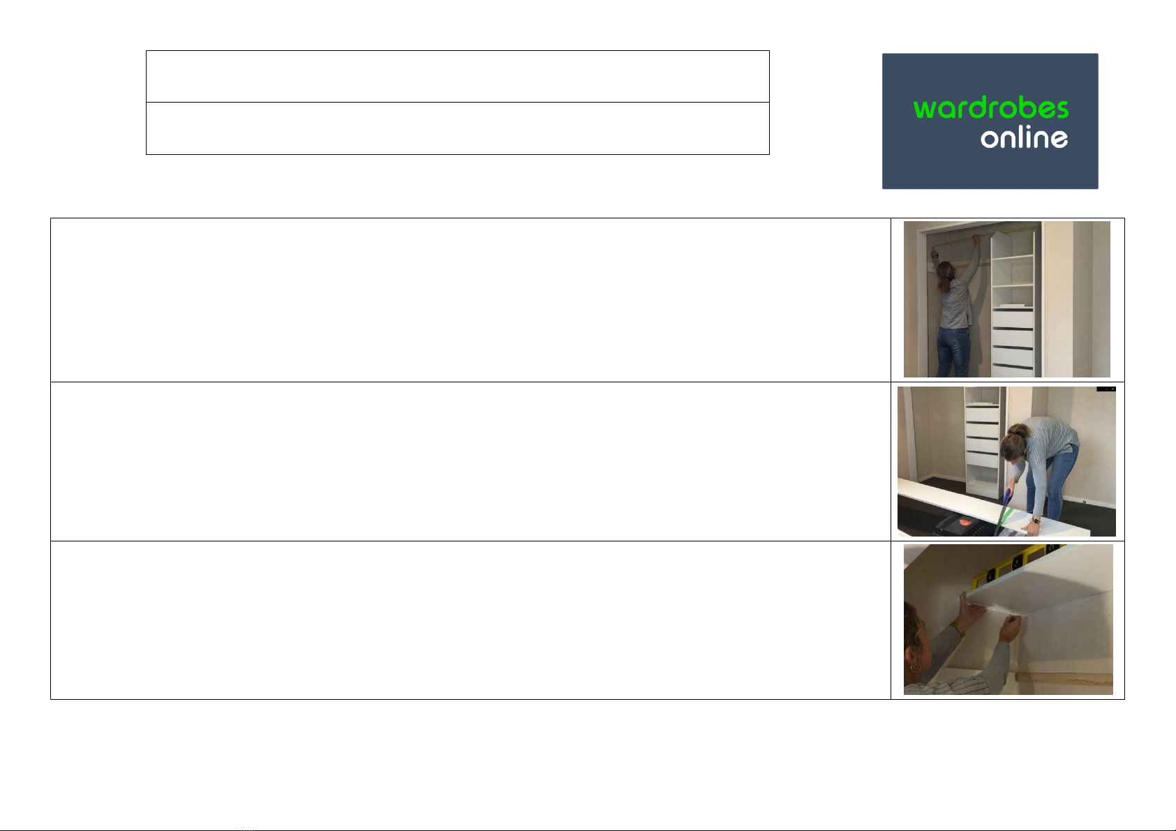
1. Measure the width of the wardrobe at the height the top shelf is to be installed.
all Brackets are marked “L” and “R” for left/right, and have a closed rim at the front and an open end at the
back which is designed so your top shelf sits hard against the back wall and the front rim stops the shelf falling
forwards. all brackets are 3mm deep each, so if your top shelf will run from wall-to-wall you will need to deduct
6mm from this measurement to get your final top shelf length.
Example: If your wall-to-wall measurement is 2000mm wide, then you need to cut your top shelf 1994mm wide.
If you are using two top shelves together (ie for wardrobes wider than 2.4m, or for walk-in wardrobes where top
shelves meet adjacently) then you will need to apply a 3mm deduction where a bracket is to be used.
2. Mark on your top shelf where you need to cut. Tip: Use masking tape along the cut line. This will give the
melamine board a cleaner finished edge. Cut the top shelf using a saw. e recommend a minimum of an 8pt saw
to cut melamine.
3. Place top shelf in position with the bracket, and pencil mark the position of the bracket (use a spirit level to
ensure your top shelf is level). Remove the top shelf, and re-align the bracket with your pencil marks. Use the
bracket as a template to mark out the holes for the screws.

4. Install wall plugs where required (gibbed walls where studs not available), and screw bracket onto wall.
5. Insert top shelf into brackets.
Screw top shelf onto top of the tower’s vertical panels – use a 25mm screw for this. If you have limited space
above the top shelf and cannot access this area with a screw driver, then secure the top shelf from underneath to
the back wall with an Econo bracket (supplied).
6. Secure the top shelf to the wall using the Econo Brackets (pictured). e recommend 2 per top shelf. These can
be installed at either end of the wardrobe, or in areas requiring more support.

INSTALLATION INSTRUCTIONS
HANGING RAILS
1. For Top Height Rail: Measure 300 fro the back of the tower/wardrobe panel.
Fro that ark easure 50 down and ark with a pencil. If you are easuring fro underneath a top shelf
bracket, easure down 40 fro the botto of the shelf bracket (this allows 10 for the bracket).
Install wall plugs where required for a stronger install.
Screw the silver bracket into the wall.
For Mid Height Rail: Measure 300 fro the back of the tower/wardrobe panel.
Fro that ark, easure 1000 down fro the top-height-rail.
Note: because floors are sometimes not level we recommend you check heights and levels as you proceed through
the installation process
2. Measure the length between the installed rail brackets to get your rail length.
*Tip allow 2.5 for each rail end, so a 600 wide gap between two walls you would cut the rail at 595
3. Mark on rail your easured length and cut the rail using a hacksaw (we reco end a ini u of an 8pt saw).
Once cut, slot rail into rail brackets.
50mm
30
0mm
4
0mm
Other manuals for Chester Series
1
Table of contents
Other Wardrobes Online Indoor Furnishing manuals