manuals.online logo
Brands
  1. Home
  2. •
  3. Brands
  4. •
  5. WAREMA
  6. •
  7. Media Converter
  8. •
  9. WAREMA climatronic converter WMS UP User manual

WAREMA climatronic converter WMS UP User manual

Operating and installation instructions
WAREMA Mobile system
WAREMA climatronic® converter WMS UP
Keep for future use!
Valid from 1st October 2019
2029598_a•en•2019-10-01 We reserve the right to make technical modifications 1
ARNINGW
Electrical installation must be performed
by a certified electrician in accordance
with VDE0100 or the legal requirements
and standards of the country in which the
device is being installed. The electrician
must observe the installation instruc-
tions included with the supplied electrical
devices.
Due to both the legal regulations for radio systems and
structural factors, the operating range of radio remote
controls is limited. Sufficient radio reception must be
ensured when planning the project. This is especially the
case where the radio signal must pass through walls and
ceilings. The control should not be installed in the immedi-
ate vicinity of metal components (steel beams, reinforced
concrete, fire doors).
 Therefore, check that the receiver is functioning proper-
ly before the final installation.
Strong local transmitter systems (e.g. WLAN) with trans-
mission frequencies identical to those of the control may
interfere with reception.
Installation
The device is intended for flush mounting in a building.
Use suitable fixing materials only.
Important information on the installation loca-
tion
The device is designed for installation in a flush-mount-
ed junction box 80 x 80 mm. The space in a 60 mm
flush-mounted switch box is usually not sufficient.
 Only lines that are used for the wiring of the WAREMA
climatronic converter should be routed into this box.
 Install the converter in such a way that the bottom of
the housing with the printed radio waves symbol
points towards the opening of the box. This ensures
the best possible radio reception.
 Check that the converter is functioning properly before
the final installation.
 Metal-clad buildings, domestic interference sources
(unshielded household appliances, television sets,
computers), supply lines and metal objects such as
sheet metal enclosures must be at least 0.5 m away
from the converter.
 When performing the installation, follow the separate
instructions of all components being connected, e.g.
when installing the weather station(s), follow the specifi-
cations in the corresponding instructions.
General information
1
2
3
4
5
6
Fig. 1 WAREMA climatronic converter WMS UP
1 Learn button
2 Test button
3 Status LED 1 (red)
4 Status LED 2 (green)
5 Status LED RS485
6 Encoding switch to S3
The WAREMA climatronic converter WMS UP (referred to
as "converter" in the following) is a flush-mounted device
that enables the control of one or more WMS networks.
This allows comfort and safety functions to be set and
managed centrally. The channel and scene commands
can also be sent from the climatronic system to the WMS
networks.
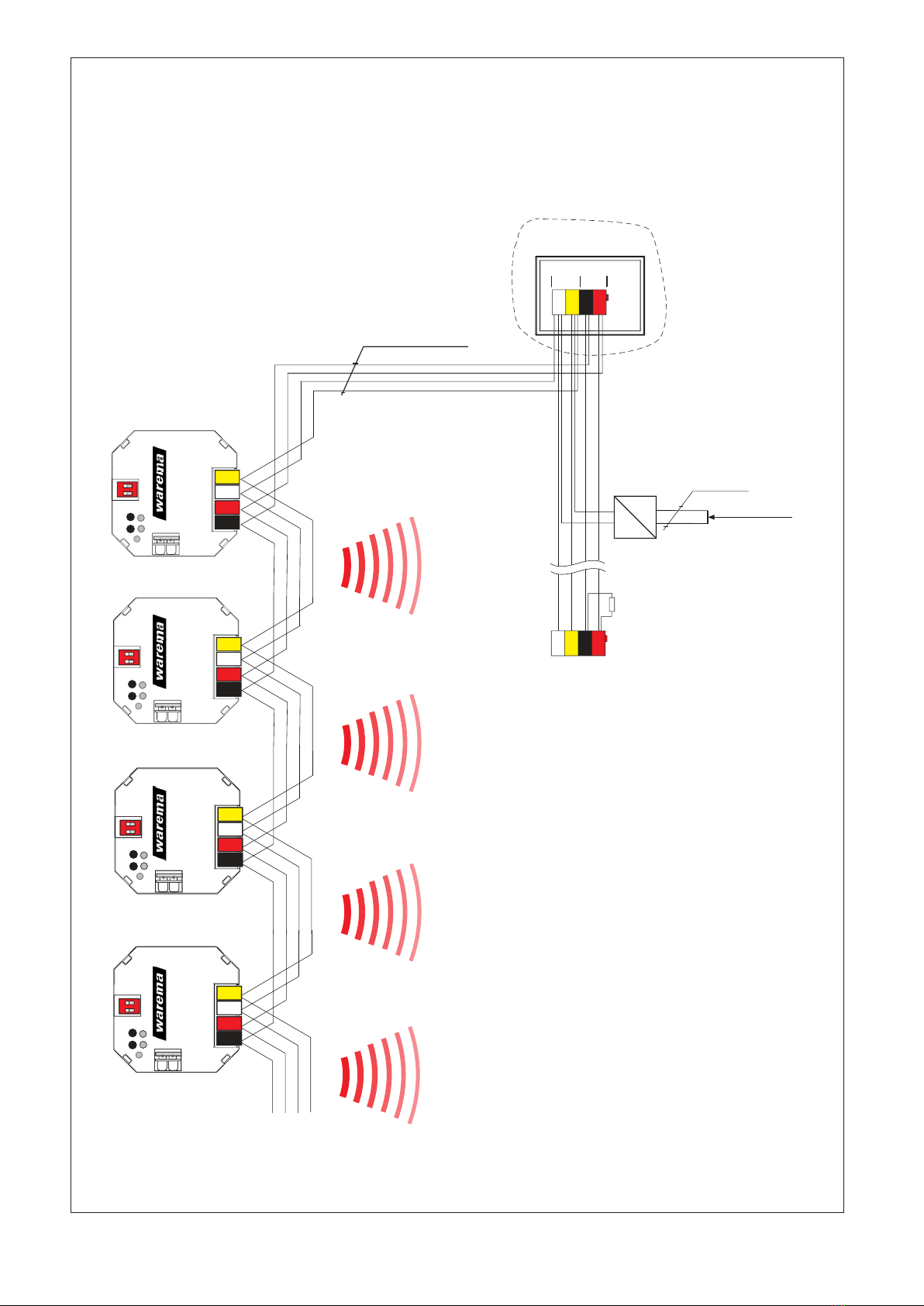
A converter is connected to the
WAREMA climatronic voa the RS485 interface.
A separate converter is required for each WMS network.
Commissioning is carried out via the WMS studio pro PC
software.
The WMS receivers, which are to react to the commands
of the WAREMA climatronic, are also allocated with WMS
studio pro.
Intended use
The WAREMA climatronic converter WMS UP is an
electronic device that was developed to forward control
commands and thus to control WAREMA Mobile System
(WMS) receivers when combined with a WAREMA clima-
tronic. The device is designed for interior installation. Any
use other than the purpose described in these instructions
requires approval from the manufacturer.
Safety instructions
These instructions address persons installing, wiring or
connecting the converter and all necessary parts. Please
contact your specialist dealer if you need additional infor-
mation.
2029598_a•en•2019-10-01We reserve the right to make technical modifications
2
Electrical connection
An on-site overload current protection device (fuse) and a
disconnecting and isolating switch to switch off the entire
system must be provided.
The unit is electrically connected according to the wiring
diagram on the reverse (Fig. 3 on page 4).
Commissioning
You can find instruction videos on our
YouTube channel at:
http://www.youtube.com/user/SonnenLichtManager/videos
We recommend commissioning using the
PC software WMS studio pro!
 Commission the WAREMA climatronic system as
normal via the WAREMA climatronic studio software
or manually via the climatronic control panel.
The converter can only be put into service using WMS
studio:
 Create a new project.
 Add the corresponding WMS devices (sensors, receiv-
ers, transmitters) and the converter.
 Adjust the settings of the individual devices.
 Establish the desired connections between the WMS
devices.
 Allocate the desired receivers to the converter.
 Transfer the configuration to the devices.
Functions
Check status of the converter
Button/
display Action/result
/
Short
 Press or briefly.
The green LED lights up for 5 s (the clima-
tronic® converter still has factory status).
Fig. 2 Using the converter in a block of flats
Connecting the RS485 side
All converters must be connected with each other via the
RS485 line and the earth line. One terminating resistor
(120 ) must be installed manually on each end of the
RS485 line. A valid protocol can be recognised via the
third LED on the converter.
The converter has two serial numbers, one for WMS and
one for the RS485 range.
Restoring the factory settings
OTICEN If the climatronic converter is deleted, no fur-
ther move commands are sent to the network.
Button/
display Action/result
+
> 10 s
 Press the and buttons on the cli-
matronic converter simultaneously for at
least 10 s.
Both LEDs flash 5 times, reset and send
the delete command
3
2029598_a•en•2019-10-01 We reserve the right to make technical modifications
Maintenance
There are no parts inside the device that require mainte-
nance.
Liability
Failure to comply with the product information contained in
these instructions and any use of the device other than its
intended use and purpose may result in the manufacturer
refusing to honour warranty claims for product damage.
In this case, liability for secondary harm to persons or
damage to property will also be excluded. Also observe
the information in the operating instructions for your sun
shading system. The automatic or manual operation of the
sun shading system when iced over as well as the use of
the sun shading system during severe weather may cause
damage and must be prevented by the user by taking
suitable precautions.
Disposal
After use, the device must be disposed of according to
legal regulations or returned to your local recycling centre.
Technical data
WAREMA climatronic®
converter WMS UP Min. Typ. Max. Unit
Supply
Operating voltage 21.6 24 26.4 V DC
Current consumption
at 24V DC 15 mA
Output
climatronic® bus connec-
tion RS485
Input control
Local voltage active 8 24 38 V DC
Local current active 0.4 1.3 2.1 mA
Local voltage inactive -0.5 0 3 V DC
RF transceiver
Transmission frequency 2.40 2.48 GHz
Transmission power <10 dBm
Reception sensitivity -101 dBm
Operating range
(environment without inter-
ference)
30 m
Housing
Dimensions in mm
(LxWxH) 49 x 49 x approx. 20 mm
Degree of protection IP30
Safety class III
Installation Flush-mounted
Miscellaneous
Conformity
Available at www.warema.com
This device meets the EMC directives for use in residential and
commercial areas.
WAREMA Renkhoff SE declares herewith that this radio system
type [WAREMA climatronic®converter WMS UP] is in compli-
ance with the current guidelines.
Ambient conditions
Operating temperature -20 60 °C
Storage temperature -20 60 °C
Humidity
(not condensing) 10 40 85 %Hrel
Degree of soiling 2
Connection
Power supply Spring terminals 0.6..0.8 mm ∅
Network Spring terminals 0.6..0.8 mm ∅
Floating switch Spring terminals 0.2..1.5 mm²
Article numbers
WAREMA climatronic
converter WMS UP 2024 335
WAREMA Renkhoff SE
Hans-Wilhelm-Renkhoff-Strasse 2
97828 Marktheidenfeld
Germany
2029598_a•en•2019-10-01We reserve the right to make technical modifications
4
BK
JY(St)Y 2x2x0.8 mm ø
WH
YE
RD
B
A
1 2
ON
0V
24V
X1 X2
LT
LED
RS485
Bus
Master/Slave
X3potfr.
switch
B
A
0V
24V
X1 X2
LT
LED
RS485
Bus
Master/Slave
X3potfr.
switch
B
A
0V
24V
X1 X2
LT
LED
RS485
Bus
Master/Slave
X3potfr.
switch
B
A
0V
24V
X1 X2
LT
LED
RS485
Bus
Master/Slave
X3potfr.
switch
RS485 Input
S3
RS485 Input
S3
RS485 Input
S3
B
A
1 2
ON
0V
24V
X1 X2
LT
LED
RS485
Bus
Master/Slave
X3potfr.
switch
B
A
0V
24V
X1 X2
LT
LED
RS485
Bus
Master/Slave
X3potfr.
switch
RS485 Input
S3
1 2
ON
1 2
ON
1 2
ON
1 2
ON
climatronic®
converter WMS
climatronic®
converter WMS
climatronic®
converter WMS
climatronic®
converter WMS
WMS Network 1
WMS Network 2
WMS Network 3
WMS Network 4
BK RDWH YE
X5
0V
A
B
24V
X6
WH YE BK RD
WAREMA climatronic®
control panel 1
climabus
terminating resistor 120 Ω
to other bus devices (e.g. weather station, actuat
ors..)
last bus device
DC
24 V
230 V
AC connecting line
230 V AC
L
N
NYM-J 3x1.5
Fig. 3 Wiring diagram

This manual suits for next models

1

Popular Media Converter manuals by other brands

D&H DH05C manual

D&H

D&H DH05C manual

GearMo GM-482422 user manual

GearMo

GearMo GM-482422 user manual

RGBlink M1 quick start

RGBlink

RGBlink M1 quick start

Sealey SA501 quick start guide

Sealey

Sealey SA501 quick start guide

Elko inels RFSG-1M quick start guide

Elko

Elko inels RFSG-1M quick start guide

Vacon NXL series user manual

Vacon

Vacon NXL series user manual

B&B Electronics 232CL9R manual

B&B Electronics

B&B Electronics 232CL9R manual

AOR ARD300 user manual

AOR

AOR ARD300 user manual

Zon DAZON 4MT08 user manual

Zon

Zon DAZON 4MT08 user manual

SIIG AV-GM01Q3-S1 user manual

SIIG

SIIG AV-GM01Q3-S1 user manual

Baumer ITD21H00 Installation and operating instruction

Baumer

Baumer ITD21H00 Installation and operating instruction

Hama 00200622 user manual

Hama

Hama 00200622 user manual

Ferrofish PULSE 16 user guide

Ferrofish

Ferrofish PULSE 16 user guide

NAD M51 quick start guide

NAD

NAD M51 quick start guide

Arcam SOLO MINI Handbook

Arcam

Arcam SOLO MINI Handbook

Connective Peripherals ES-R-2 01B-M Series manual

Connective Peripherals

Connective Peripherals ES-R-2 01B-M Series manual

Coretec VCX-2400-E Installation and operating instructions

Coretec

Coretec VCX-2400-E Installation and operating instructions

SRS Lighting DSR10-RDM-N instruction manual

SRS Lighting

SRS Lighting DSR10-RDM-N instruction manual

manuals.online logo
manuals.online logoBrands
  • About & Mission
  • Contact us
  • Privacy Policy
  • Terms and Conditions

Copyright 2025 Manuals.Online. All Rights Reserved.