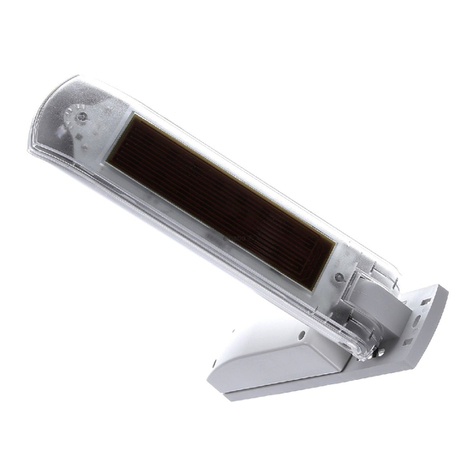
WAREMA Omnexo Weather station pro User manual

1
warema_2052445_alhb_en_v2•2023-04-01 We reserve the right to make technical modifications
ARNINGW
If hazard-free operation cannot be
assumed, the device must not be started
or must be deactivated. This assumption is
justified if:
the housing or the connecting lines show
signs of damage,
the device is no longer working.
ARNINGW
The sensor may only be operated with
safety extra low voltage.
ARNINGW
An automatically controlled mechanism
may begin to move unexpectedly!
Therefore, never place any objects in the area of
movement of an automatically controlled mechanism.
Disconnect the power supply of the controlled sun
shading products before maintaining or cleaning the
products.
Function
The Omnexo Weather station pro collects measuring
values for brightness, dawn/dusk, wind speed, wind
direction, precipitation and outside temperature.
It is equipped with a GPS receiver to transmit the current
time, date and geographical position.
The weather station is connected as a network device via a
four-wire bus line.
The 24 V DC power supply is provided by a separate
power supply unit.
Brightness measurement
The brightness is recorded by four photo sensors arranged
at right angles (see Fig. 3 on page 2).
A second measuring range is used to collect the dawn/
dusk values.
The measuring values can be switched between ambient
brightness (in Lux) and radiation on the facade (infrared
radiation in W/m²).
Wind measurement
The wind is measured by four ultrasound transducers
arranged at right angles.
These are used to record both the wind speed and
direction.
General information
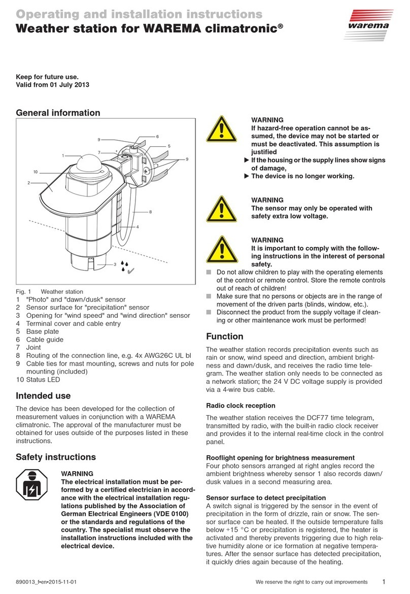
Fig. 1 Omnexo Weather station pro
The Omnexo Weather station pro collects measuring
values for brightness, wind speed and wind direction,
precipitation and outside temperature and sends the
current time, date and geographical position to the
receiver via GPS. The measuring values are sent to the
Omnexo Central control unit via the bus connection and
the connected sun shading products are correspondingly
controlled on the basis of this data. The weather station is
mounted outside by means of a supplied fixing bracket or
an optional pole.
Intended use
The Omnexo Weather station pro is an electronic device
for the collection of measuring values in combination
with an Omnexo Central control unit. The approval of
the manufacturer must be obtained for any use of the
device other than its intended purpose specified in these
instructions.
Safety instructions
ARNINGW
The electrical installation (assembly)/
dismantling must be performed by a
certified electrician in accordance with
VDE0100 and/or with the standards
and legal requirements pertaining to
the respective country. The electrician
must observe the installation notes and
instructions included with the electrical
devices supplied.
Omnexo Weather station pro
Operating and installation instructions
Valid from
1 April 2023
Keep for future use.

warema_2052445_alhb_en_v2•2023-04-01We reserve the right to make technical modifications
2
Precipitation measurement
Precipitation in the form of a fine drizzle, rain or snow is
recorded.
Precipitation is optically measured.
In order to prevent it from activating due to high humidity,
the sensor surface is heated.
The slope of the sensor surface provides the required
angle to allow water to run off the sensor surface.
Temperature measurement
The outside temperature is recorded.
The temperature is measured by ultrasound sensors.
GPS
The Omnexo Weather station pro is equipped with an
integrated GPS receiver.
This records the date and time along with
determining the geographical position.
Integrated heating
The weather station is equipped with a built-in heating unit.
This largely prevents ice or snow accumulating on the
device.
Installation
Install the weather station using the mounting bracket
provided.
120 mm
140 mm
40 mm
55 mm
Fig. 2 Wall-mounted using the mounting bracket
The weather station must be mounted in an upright
position with a maximum inclination of ±2° and set up
to also record the sun when it's low.
Install the weather station in an easily accessible
location at the highest point of the roof structure. To
avoid hindering accurate wind evaluation, do not mount
the device away from the wind.
For facade installation, select a position that allows the
measuring values to be collected for all hangings to be
controlled.
For the system to function properly, precipitation must
be able to hit the sensor surface without interference.
In order to ensure dawn/dusk control, the weather
station should be positioned so that the photodiodes
cannot be influenced at night by street or garden
lighting or other external light sources (e.g. flashlights).
Trees, bushes or parts of the building can shade the
sensors during the course of the day, resulting in an
incorrect measurement result. Therefore, select the
installation location carefully.
The weather station can also be mounted on an
optionally available pole. This requires an additio-
nal fixing adapter (special accessory).
To obtain correct and highly accurate measure-
ment values, the weather station must be installed
in direct sunlight.
Therefore, when the sun is shining brightly, the tem-
perature values measured with other thermometers
in the shade may differ from the values measured
here.
The function of the ice monitoring is not impaired.
Types of installation
Alignment of the photodiodes
EIN AUS
Photo 4
Photo 2
Photo 1 Photo 3
Fig. 3 Position of the photodiodes on the device
Installation version
Fig. 4 Wall installation on
pole
Fig. 5 Mast installation with
50 cm dia. adapter on
pole (dia. 49 mm)

3
warema_2052445_alhb_en_v2•2023-04-01 We reserve the right to make technical modifications
Electrical connection
An on-site overload current protection device (fuse) and a
disconnecting and isolating switch to switch off the entire
unit must be provided.
Use a line that is approved for the operating voltage
and is resistant to weather and UV rays (suitable for
outdoor use), e. g. as 4xAWG20ULSW.
The supply line must be routed so that water cannot
enter into the device or into the building.
The total line length must not exceed 1,200m if a
twisted pair line is used and routed in an interference-
proof manner.
Pay attention to the minimum voltage at the weather
station (voltage drop) and use a separate power supply
unit for the power supply if necessary.
Connect the weather station to the Omnexo Central
control unit as per wiring diagram Fig. 6 on page 5.
The bus lines must be provided with terminating
resistors at the beginning and end of the line.
HUBs are needed for longer line lengths.
If you are using the optional Omnexo Weather station
pro power supply unit 24 V DC/1.3 A AP (article
number 2057430), a branch line of max. 10 m to the
Omnexo Weather station pro is permissible
Please take out the ID labels from the devices
and give them to your system integrator (see also page
4). A clear allocation of the devices and ID labels must
be ensured.
This device meets the requirements on electromagnetic
immunity and electromagnetic interference for use in
residential and commercial environments.
For operation, an external power supply unit must
be installed in the vicinity of the Omnexo Weather
station pro.
If the Omnexo Weather station pro is the last bus
device in the bus line, the terminating resistor
needs to be manually set (see Fig. 6 on page
5, illustration displays active terminating resis-
tor)
Depending on the installation situation, you can
also directly route the line of type JY(St)Y to the
Omnexo weather station pro. It must be ensured
that the line is protected against UV radiation (e.g.
in a conduit, tube) along its entire length.
Commissioning
To be able to commission the weather station, it must be
set up in the Omnexo software. To determine the serial
number, place the magnet (in central control unit scope of
delivery) on the ID label until the status LED lights up for
confirmation. (see Fig. 6 on page 5.)
Alternatively, you can manually enter the serial number
manually (see label on device).
When commissioning, note that the weather station
has an internal temperature correction feature that
improves measurement accuracy.
When the operating voltage is first switched on, a
temperature measurement is taken at the weather
station.
Maintenance
There are no parts within the device that require
maintenance.
Cleaning
The weather station should be checked for dirt (e.g. bird
droppings) and cleaned carefully four times a year.
Clean the device with a soft damp cloth. Steam or high
pressure washers, abrasive sponges, abrasive agents
and solvents such as alcohol or petroleum must not be
used!
Liability
Failure to comply with the product information in these
instructions and any use of the device other than its
intended use may result in the manufacturer refusing to
honour warranty claims for product damage. In this case,
liability for secondary harm to persons or damage to
property will also be excluded. Observe the information in
the operating instructions for your sun shading system. The
automatic or manual operation of the sun shading system
while iced over and the use of the sun shading system
during severe weather may cause damage and must be
prevented by the operator through suitable precautions.
Obligations for the disposal of electrical
devices
A marking with this symbol indicates the following
obligations under the scope of legal regulations:
The owner of this electrical device must dispose of it
separately from unsorted municipal waste for further
recycling.
Used batteries and accumulators that are not enclosed
in the old device, as well as lamps/bulbs that can be
removed from the old device without breaking, must be
disposed of separately.
Distributors of electrical devices and disposal
companies are obliged to take back the equipment free
of charge.
The owner must take it upon themselves to delete any
personal data contained in the electrical device prior to
disposal.

warema_2052445_alhb_en_v2•2023-04-01We reserve the right to make technical modifications
4
Technical data
Omnexo Weather station
pro min. type max. Unit
Supply
Operating voltage (SELV) 21.6 24 26.4 VDC
Current consumption 30 1200 mA
Temperature sensor*
Measuring range -20 60 °C
Resolution 0.5 °C
Accuracy ±2 °C
4 direction-dependent photo sensors
Measuring range 0 100 klx
Resolution 1 klx
Accuracy ±10 %
Dawn/dusk measuring range 0 1000 lx
Resolution at dawn/dusk 1 lx
Accuracy at dawn/dusk ±10 %
Radiation transmission onto facade
Measuring range 0 1300 W/m²
Resolution 1 W/m²
Accuracy ±10 %
Wind speed
Measuring range 0 25 m/s
Resolution 1 m/s
Accuracy ±1 m/s
Wind direction
Measuring range 0 360 °
Resolution 45 °
Precipitation sensor
Measuring range Precipitation yes/no
GPS module
Parameter Position, date, time
Omnexo interface
Bus interface RS485 (two-wire bus)
Housing
Dimensions 145 x 120 x 145mm (WxHxD)
Degree of protection IP44
Safety class III
Installation Wall/pole
Miscellaneous
Conformity
specified under
www.warema.de/ce
This device complies with the EMC directives for use in
residential and commercial areas.
WAREMA Renkhoff SE declares herewith that the radio system
type Omnexo Weather station pro is in compliance with the
2014/53/EU guideline.
Software class A
Omnexo Weather station
pro min. type max. Unit
Ambient conditions
Operating temperature -30 60 °C
Storage temperature 0 70 °C
Humidity
(not condensing)
10 100 %RH
Degree of soiling 2
Connection
Omnexo interface Spring terminals
Permissible line cross-section
single-wire/fine-wire without
ferrule
0.5 - 1.5mm²
Permissible line cross-section
fine-wire with ferrule
0.5 - 0.75mm²
Stripping length 8 - 9mm
Maximum line length
(for recommended
line type)
10m
Recommended line type 4 x AWG 20 C UL
(resistant to UV rays)
Article numbers
Omnexo Weather station pro 2047095
Optional accessories
Omnexo Weather station pro
power supply unit 24 V DC /
1.3 A AP
2057430
Connecting line 4 x AWG
20 C UL (resistant to UV rays)
3m
2058245
Connecting line 4 x AWG
20 C UL (resistant to UV rays)
10m
2058246
Pole L = 35cm;
Dia. 20mm, wall mounting,
wall distance 150mm
632075
Pole L = 100cm;
Dia. 20mm, wall mounting,
wall distance 150mm
632085
Adapter for pole
dia. 50 mm
632095
WAREMA Renkhoff SE
Hans-Wilhelm-Renkhoff-Strasse 2
D-97828 Marktheidenfeld, Germany
Germany
KEEP IN A SAFE PLACE FOR COMMISSIONING!
Affix the ID label for the Omnexo Weather station pro here
Note down installation location here

5
warema_2052445_alhb_en_v2•2023-04-01 We reserve the right to make technical modifications
4 x AWG 20 UL black
JY(St)Y 4 x 2 x 0.8 mm ∅
junction box
on-site
Alternatively: Optional
power supply unit
(art. no. 2057430)
View from below
Strain relief
(fixing on the terminal
via cable tie)
Switch for integrated terminating
resistor 120 Ω
ferrules must
be used
‒
‒
+ + A B
The wire colours may vary
depending on the
type of lines used.
*Recommended line type for
outdoor installations
** Insert bridge
**
-
+
AB
ON OFF
0 V B24 VA
DC
24 V
230 V
AC
connecting line
230 V AC
L
N
NYM-J 3x1.5
Fig. 6 Omnexo Weather station pro with power supply unit wiring diagram
Table of contents
Other WAREMA Weather Station manuals