WAREMA WMS Weather Station Eco User manual

Operating and installation instructions
WAREMA Mobile system
WMS Weather station eco
Keep for future use!
Valid from 1 January 2020
2024730_d•en•2020-01-01 We reserve the right to make technical modifications 1
AUTIONC
Never press buttons on your transmitter arbi-
trarily without line of sight to the sun shad-
ing product. Children may not play with this
product – keep remote controls and trans-
mitters out of the reach of children!
OTICEN The receiver (e.g. the radio plug receiver,
radio tubular motor) cannot function in the
event of a power failure. Therefore, raise the
sun shading system early enough in case of
an approaching storm.
Due to both legal regulations for radio systems and struc-
tural factors, the operating range of radio remote controls
is limited. Sufficient radio reception must be ensured when
planning the project. This is especially the case where the
radio signal must pass through walls and ceilings. The
control unit should not be installed in the immediate vicin-
ity of metal components (steel beams, reinforced concrete,
fire doors).
Therefore, check that the receiver is functioning prop-
erly before the final installation.
Strong local transmitter systems (e.g. WLAN) with trans-
mission frequencies identical to those of the control
system may interfere with reception.
Installation
This device is designed for surface mounting on a build-
ing facade. It can also be mounted on a pole using the
included cable ties.
Included fixing materials:
2 screws 4.5 x 40 mm
2 screw anchors 6mm
2 spacers for wall and ceiling installation (Fig. 2)
2 steel cable ties 360 mm
Use suitable fixing materials only. Depending on the sub-
structure (e.g. plastered outer insulation), other screws and
screw anchors may need to be used.
Important information on the installation loca-
tion
Attach the device outdoors at a readily accessible but
raised location.
Metal-clad buildings, domestic interference sources
(unshielded household appliances, television sets,
computers), supply lines and metallic objects such
as sheet metal enclosures must have a distance of at
least 0.5 m from the weather station.
General information
14
23
5
Fig. 1 WMS weather station eco
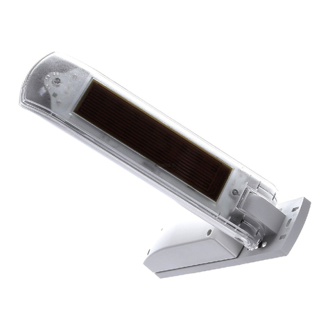
1 Solar panel
2 Photodiodes
3 Wind wheel
4 Joint
5 Mounting plate with cover
Three storage batteries for the power supply are found
under the cover.
The WMS Weather station eco enables the wireless control
of sun shading drives and is equipped with sensors for
brightness and wind speed. The station is solar powered.
The device transmits weather data to WMS-compatible
receivers.
Intended use
The WMS Weather station eco is an electronic device to
control WMS receivers. Any use other than the purpose
described in these instructions requires approval from the
manufacturer.
Safety instructions
ARNINGW
An automatically controlled mechanism
may begin to move unexpectedly!
Therefore, never place any objects in the area of move-
ment of an automatically controlled mechanism.
Disconnect the power supply of the controlled sun
shading products before maintaining or cleaning the
products.

2024730_d•en•2020-01-01We reserve the right to make technical modifications
2
Install the device in a position in which the wind wheel
is as close as possible to horizontal (housing inclina-
tion of 15°). When installing the device on sloped
areas, the sensor can be positioned horizontally using
the joint (Fig. 1).
When selecting the installation location, ensure that the
solar panel is sufficiently supplied with sunlight. For
example, an overhanging roof may shade the panel at
certain times of the day. Also avoid installing it on the
north face of buildings.
Before installing the device, consider that trees, bushes
or parts of the building may shade the photo sensor
during the course of the day. In this case, the sensor
cannot deliver exact measuring values and the results
will be incorrect. Therefore, select the installation loca-
tion carefully.
When selecting an installation location, ensure that the
photo sensor is exposed to the same brightness condi-
tions as the sun shading system being controlled. This
means that you need to position the photodiodes ac-
cording to the building facades being shaded. Ideally,
the weather station is oriented in the same direction as
the sun shading product being controlled.
Install the device in the vicinity of the sun shading
product although not in places where the sun shading
system affects the wind currents; otherwise, the sensor
will not provide the correct wind evaluation.
Separate spacers are included for wall and ceiling
installation. They prevent cracking and deformation of
the plastic (Fig. 2).
Fig. 2 Clipping the separate spacers into the threaded hole
Additional installation information can be found in the
documentation of your sun shading system.
Mounting plate
0
13,75
4,5
9,0
207,5
199
4,5
9,0
56
4,5
9,0
134,5
Fig. 3 Dimensions
OTICEN Before you close the cover and screw it into
place after installation on a wall, ceiling or
pole, activate the WMS Weather station eco.
To do this set the switch on the printed circuit
board to "on" (see Fig. 4)
o
on
o
on
Fig. 4 Switch for activating the WMS Weather station eco
Wall installation
Fig. 5 Wall installation
Clip one of the included spacers into the threaded hole
(horizontally or vertically, Fig. 2).
Attach the weather station to a suitable substructure
using the included screws and screw anchors as
shown (Fig. 5).
The line must be correctly positioned in the guide
on the back of the mounting plate to ensure it is not
pinched during installation.
Tighten the screw on the joint.
Ceiling installation
Fig. 6 Ceiling installation
Loosen the screw on the weather station joint.
Swing the mounting plate of the weather station up by
90° (or by the necessary angle).
Retighten the screw on the joint.
Clip one of the included spacers into the threaded hole
(horizontally or vertically, Fig. 2).
Attach the weather station to a suitable substructure
using the included screws and screw anchors as
shown (Fig. 6).

3
2024730_d•en•2020-01-01 We reserve the right to make technical modifications
The line must be correctly positioned in the guide
on the back of the mounting plate to ensure it is not
pinched during installation.
Pole installation
Fig. 7 Pole installation and steel cable ties locking mechanism
Remove the thin (triangular) webs at the top and bot-
tom edge of the mounting plate using a wire cutter
(Fig. 7 *).
Pass the included steel cable ties through the mounting
plate openings as shown. The cable tie closures must
face outwards.
Correctly align the weather station and attach it to a
securely mounted pole. No lines may be pinched.
Turn both ends of the cable tie inwards, one at a time,
using needle-nosed pliers. Check that the weather sta-
tion cannot be turned.
Tighten the screw on the joint.
Operating elements
6
8
7
9
Fig. 8 Operating elements, view from below
Pos. Fig. Function
6Status LED 2 (green)
Indicates different states of the weather station
using different flash patterns
7Status LED 1 (red)
Indicates different states of the weather station
using different flash patterns
8Learn button
To assign the weather station to a channel or
delete it
Press briefly: transmit the learn report for the
channel
Press for longer than
5 s:transmit the delete report for the channel.
9Test button
To transmit a test report to the WMS network
OTICEN The weather station goes into sleep mode
regularly to save energy. It can be awakened
for one minute by briefly pressing the button.
Initial operation
You can find instruction videos on our
YouTube channel at:
http://www.youtube.com/user/SonnenLichtManager/videos
We recommend commissioning using the
PC software WMS studio pro!
Activate the WMS weather station by flipping the switch
on the printed circuit board to "on". Learning can then
be started immediately.
The WMS weather station will now be in learn mode for
two minutes and can be added to the WMS network.
During these two minutes, the status LED flashes green
every 5 seconds.
Exception (batteries too weak):
The status LED does not flash green every 5 seconds:
Commissioning via USB
o
on
Fig. 9 USB port for charging the batteries in exceptional cir-
cumstances
Unscrew the housing base and connect a micro USB
cable to the USB port.
The sensor will now also be in learn mode for two minutes
here and behaves as described above.
OTICEN If the learning in is not completed within these
two minutes, you must put the sensor in learn
mode again. To do this, push the sliding switch
to the left and then to the right again or press
and hold the button for at least 5 seconds
(the green LED flashes).
Add the WMS weather station with the WMS studio
pro PC software or an WMS Hand-held transmitter to
the network. You can then allocate the WMS weather
station to the desired channels (actuators). See section
"Comissioning functions".
At regular intervals, the weather station now transmits
weather data to the WMS network. The assigned actua-
tors evaluate this information and react according to
their parameterization.
OTICEN After the weather station is assigned to the
desired actuators, it can be operated as de-
scribed under "Commissioning functions".

2024730_d•en•2020-01-01We reserve the right to make technical modifications
4
Commissioning functions
Adding a weather station to the network (scan-
ning)
To be able to transmit weather data to WMS receivers, the
WMS Weather station must belong to the corresponding
radio network. The WMS Weather station can be detected
by a WMS hand-held transmitter and added to the network
of the WMS hand-held transmitter (hereinafter described
using the example of a WMS hand-held transmitter com-
fort).
OTICEN Activate the WMS weather station eco before
commissioning.
To do this set the switch on the printed circuit
board to "on" (see Fig. 4)
Button/
display Action/result
Wake up the WMS hand-held transmitter
comfort with any product button
Press the learn button on the WMS hand-
held transmitter for approx. 5 seconds
+ lights up green; the transmission LED
flashes. For several seconds, the WMS
hand-held transmitter comfort scans the
operating range for receivers.
e.g. When the scanning procedure is complet-
ed, the located receivers are displayed in
the upper row of LEDs (here, for example,
2receivers).
RED: New receiver
GREEN: The receiver already belongs to
the network
Receivers that already belong to a differ-
ent network are not located during scan-
ning.
Select the weather station using the arrow
buttons.
(You can use the button to check
which receiver is currently selected. The
product waves: The LEDs of the weather
station and the control symbols on the
WMS hand-held transmitter comfort light
up for 2 s.)
e.g. The LED for the selected weather station
flashes red. No product buttons light up.
Press the button
e.g. The LED for the selected weather station
flashes green. The weather station has
been added to the network.
Briefly press the learn button to leave the
learn mode.
Deleting the weather station from the network
(restoring the factory settings)
You can completely delete the weather station from the
network if you decide to remove it or assign it to a different
network.
OTICEN When you delete sensors from the network,
they are deleted from all reachable receivers in
the network.
The control functions of the receivers remain
active and must be separately deactivated for
each receiver. If, for example, wind monitoring
was set for a receiver, the product is automati-
cally retracted to protect it against damage if
the heartbeat function fails.
Example 1: Delete the weather station directly from the
network using the push buttons.
Button/
display Action/result
+
> 10 s
On the weather station, press the and
buttons simultaneously for at least 10
s.
The LEDs flash 5 times.
GREEN+RED:Reset and transmit delete
command
RED only: Charge status too low, ac-
tion is not executed
All actuators and transmitters of the net-
work wave. The weather station has been
deleted from the network and has been
restored to the factory settings and will
now be in learn mode for two minutes.
Example 2: Delete the weather station from the network
using a WMS hand-held transmitter comfort.
Button/
display Action/result
OTICEN After every press of a button the weather sta-
tion remains awake for the next minute. It then
returns to sleep mode to save energy. Briefly
press the button on the weather station to
wake it back up.
/
Brief
Waking up the weather station
Press or briefly.
The LED flashes three times.
GREEN: Charge sufficient
RED: Charge status low
OTICEN If the LED lights up for 5 s, the
weather station already has factory
settings.
Wake up the WMS hand-held transmitter
comfort with any product button
Press the learn button for approx. 5sec-
onds
+ lights up green; the transmission LED
flashes. For several seconds, the WMS
hand-held transmitter comfort scans the
operating range for receivers.
e.g. When the scanning procedure is complet-
ed, the located receivers are displayed in
the upper row of LEDs (here, for example,
2receivers).
RED: New receiver
GREEN: The receiver belongs to the
network.
Select the weather station using the arrow
buttons.
(You can use the button to check
which receiver is currently selected. The
product waves: The LEDS of the weather
station light up for 2 s; all control symbols
lights up on the WMS hand-held transmit-
ter comfort.)

5
2024730_d•en•2020-01-01 We reserve the right to make technical modifications
Button/
display Action/result
e.g. The LED for the selected weather station
flashes green. No product buttons light up.
+ Press the and buttons simultane-
ously.
e.g. The LED for the selected weather station
flashes red. A running light runs through
the lower row of LEDS.
The selected receiver waves.
Press the learn button briefly
e.g. The LED of the selected receivers flashes
red. No product buttons light up.
The weather station was deleted from the
network and now has the factory settings.
Briefly press the learn button to leave the
learn mode.
OTICEN How to delete the weather station from the
network using a WMS Central transmitter is
described in the operating instructions of the
WMS Central transmitter.
Assigning a weather station to channel
For a WMS receiver to be able to evaluate the weather
data, the weather station must be allocated to the chan-
nel of the receiver. Each WMS receiver can be assigned a
maximum of four sensor products.
OTICEN How to assign the weather station to a channel
using a WMS Central transmitter is described in
the operating instructions of the WMS Central
transmitter.
Button/
display Action/result
On the WMS hand-held transmitter com-
fort, select the product type and channel
to which you wish to allocate the weather
station.
Press the learn button on the WMS hand-
held transmitter comfort briefly.
lights up green and the product button
and selected channel flash.
Brief
On the weather station, press briefly.
The LED flashes three times.
GREEN: The learn report is transmitted
RED: The learn report is transmitted,
the charge status is low
The transmission LED on the WMS
hand-held transmitter comfort lights up
green for 2 seconds and the symbol
goes out. The receivers belonging to the
channel wave.
The weather station is allocated to all receivers in the
channel. The control functions can now be set in these
receivers.
OTICEN If four sensor products have already been as-
signed to a receiver, you must first delete one
of these sensors before you can assign the
weather station to the receiver.
OTICEN If the weather station is assigned to a WMS
receiver that has already been combined with a
WMS wind sensor (e.g. for patio awnings), this
receiver only evaluates the wind information of
the WMS wind sensor. All other weather data of
the weather station can be evaluated normally
by this receiver.

2024730_d•en•2020-01-01We reserve the right to make technical modifications
6
Deleting the weather station from a channel
To delete the weather station from the receivers of a chan-
nel again, proceed as follows:
OTICEN How to delete the weather station from a
channel using a WMS Central transmitter is
described in the operating instructions of the
WMS Central transmitter.
Button/
display Action/result
On the WMS hand-held transmitter com-
fort, select the product type and channel
to which you wish to allocate the weather
station.
Press the learn button on the WMS hand-
held transmitter comfort briefly.
lights up green and the product button
and selected channel flash.
> 5 s
On the weather station, press the but-
ton for at least 5 s.
The LED flashes twice
GREEN: The delete report is transmitted
RED: The delete report is transmitted,
the charge status is low
The transmission LED on the WMS
hand-held transmitter comfort lights up
green for 2 seconds and the symbol
goes out. The receivers belonging to the
channel wave.
The weather station is now deleted from all receivers of
the channel. If necessary, adjust the parameterisation of
the control functions for the receivers of this channel.
Testing the weather station
The weather station transmits a test report to the network
at the push of a button. All receivers into which the weath-
er station was learned wave. The measurement values can
be displayed on a WMS Central transmitter.
Button/
display Action/result
Brief
On the weather station, press briefly.
The LED flashes three times.
GREEN: The test report is transmitted
RED: The test report is transmitted,
the charge status is low
All receivers to which the weather station
is assigned wave.
Measuring values can be displayed on a WMS central
transmitter or in the special menu of a WMS hand-held
transmitter comfort.
Control functions
Switching the comfort control functions on/off
You can switch the comfort controls off and on temporarily
to prevent the sun shading products from moving automat-
ically. The command always applies to all receivers that
were learned into the WMS transmitter. Safety functions
cannot be switched on and off.
Button/
display Action/result
Wake up the WMS hand-held transmitter
comfort with any product button
Press the control button.
+
The and the sun and dawn/dusk con-
trol symbols light up.
The LEDs below the symbols indicate the
type of switch command:
GREEN: Switch on the control functions
RED: Switch off the control functions
The transmission LED lights up for 2
seconds
GREEN: The control functions were
switched in all receivers
RED:
Not all receivers could be
reached; switch the control func-
tions OFF and ON again (or ON
and OFF).
OTICEN The WMS hand-held transmitter comfort always
remembers the command transmitted last.
When the control button is pressed again, the
WMS hand-held transmitter comfort transmits
the opposite command (ON - OFF - ON - ...).
Displaying/parameterising the control functions
Your products can be automatically controlled in the WMS
network as a function of sunlight, dawn/dusk or wind.
The parameters of the control functions can be displayed
and changed via the WMS central transmitter or the WMS
hand-held transmitter comfort.
OTICEN Only those parameters are displayed that
belong to the selected product type (e.g. there
is no precipitation monitoring for the "light"
product type).
The parameters of the wind safety function can
be displayed but not changed.
Temperature functions are only available via the
WMS central transmitter.
Button/
display Action/result
Select the product type and channel that
you wish to parameterise.
e.g. The LED below the channel number lights
up.
Press the info button briefly.
+
e.g.
lights up
The upper row of LEDs shows how many
receivers belong to the selected chan-
nel. One LED lights up in green for each
receiver (one receiver in the example).

7
2024730_d•en•2020-01-01 We reserve the right to make technical modifications
Button/
display Action/result
Press the info button repeatedly until the
desired control function lights up.
e.g.
The LED below the control symbol shows
the state of the control function.
GREEN: Active
RED: Inactive
e.g.
...
The parameter value of the current control
function is displayed in the upper row of
LEDs (here, limit value 2 of the previously
selected sun control).
RED: Value 0; the control function is
off
GREEN: Values 1 to 9
FLASHES:Multiple receivers with differ-
ent limit values in the channel.
The value of the first receiver is
displayed.
You can now change this parameter value or switch to
the next info mode using the button:
Use the arrow keys ( + light up) to
change the parameter value.
e.g.
...
The upper row of LEDs shows how the
value changes (new value = 1)
Press the button
The transmission LED lights up for 2
seconds
GREEN: The parameter value was saved
in all receivers of the channel
RED: Not all receivers could be
reached; press the button
again.
Leave the info mode using the info button
( is no longer lit).
OTICEN Move commands cannot be sent while the info
mode is active ( lights up).
In the info mode, the WMS hand-held transmit-
ter comfort switches off one minute after the
last press of a button.
If multiple receivers belong to a single channel,
the set parameter value is written to all receiv-
ers of that channel.
Display of the limit values using the WMShand-
held transmitter comfort
The following table shows the limit values that the display
values of the LED lines on the WMS hand-held transmitter
comfort represent.
Display of the limit values set in the receiver:
The WMS hand-held transmitter comfort converts the
limit values read out of the receiver to values that can be
displayed on the 10 LEDs in the upper row of LEDs. The
displayed limit values therefore only approximate the limit
values from the receiver.
Display of the limit values read out of the receiver
Step Photo
(klx)
Dawn/dusk
(lx)
Wind
(m/s)
0 OFF OFF OFF
1 3...12.5 2...22 0.0...5.5
2 13...17.5 24...36 6.0...6.5
3 18...22.5 38...52 7.0...7.5
4 23...27.5 54...70 8.0...8.5
5 28...32.5 72...90 9.0...9.5
6 33...37.5 92...126 10.0...10.5
7 38...42.5 128...174 11.0...11.5
8 43...47.5 176...300 12.0...12.5
9 48...100 302...500 13.0...25.0
If the first LED (level 0) lights up for the wind limit value,
the wind monitoring is switched off.
If 5 LEDS (level 4) light up, the limit value set in the re-
ceiver is between 8.0 and 8.5 m/s.
Display of the limit values when making settings using
the arrow buttons:
When you change the limit values using the arrow buttons,
the display shown in the upper LED row corresponds to
the values in the following table. These values are written
into the receivers when the data is saved.
Display while limit values are being set
Step Photo
(klx)
Dawn/dusk
(lx)
Wind
(m/s)
0 OFF OFF OFF
1 10 16 5
2 15 30 6
3 20 46 7
4 25 60 8
5 30 80 9
6 35 100 10
7 40 150 11
8 45 200 12
9 50 400 13
If the first LED (level 0) lights up for the photo limit value,
the sun control is switched off.
If you change the value until 7 LEDs light up (level 6), a
limit value of 35 klx is saved in the receivers of the se-
lected channel when the button is pressed.

2024730_d•en•2020-01-01We reserve the right to make technical modifications
8
Changing the wind speed limits (specialist
dealers only)
AUTIONC
Changing these settings may impair the
safety of the unit or reduce its effectiveness.
It is better to consult a qualified specialist
if you are not sure about the effects of a
change.
For your sun shading product to be protected properly, the
limit value above which a wind alarm is triggered needs to
be set for that particular product (type, width, projection,
etc.).
Set the limit values as required for your system (to the
most wind-sensitive product in the respective channel).
OTICEN How to change the limit values using a WMS
central transmitter is described in the operating
instructions of the WMS central transmitter.
Changing the wind speed limits with a WMS hand-held
transmitter comfort
The actual wind speed values in m/s represented by the
WMS hand-held transmitter comfort display are shown in
the tables in the previous section.
Button/
display Action/result
The wind speed limit can only be changed if the WMS
Plug receiver was first learned into the WMS hand-held
transmitter comfort.
Select the product type and channel that
you wish to parameterise.
e.g. The LED below the channel number lights
up
Press the mode button with a pointed
object until lights up and mode 0 is
selected.
OTICEN The mode button must be pressed
before the WMS hand-held trans-
mitter comfort returns to sleep
mode
.
If you press the mode button for
too long and a higher mode is
displayed: Release the button and
press and hold it again; the pro-
cess restarts at 0.
+ and the LED above the 0 light up in
red
Briefly press the learn button to activate
the mode.
The LED above the number 0 briefly lights
up in green
The sun control is displayed automatically.
Press the info button repeatedly until the
symbol for the wind monitoring lights up.
The LED below the control symbol shows
the state of the control function.
GREEN: Active
RED: Inactive
Button/
display Action/result
e.g.
...
The parameter value of the wind monitor-
ing is displayed in the upper row of LEDs
(here, limit value 2).
RED: Value 0; the control function is
off
GREEN: Values 1 to 9
FLASHES:Multiple receivers with differ-
ent limit values in the channel.
The value of the first receiver is
displayed.
Use the arrow keys ( + light up) to
change the parameter value.
e.g.
...
The upper row of LEDs shows how the
value changes (new value = 1)
Press the button
The transmission LED lights up for 2
seconds
GREEN: The parameter value was saved
in all receivers of the channel
RED: Not all receivers could be
reached; press the button
again.
Leave the dealer mode with the mode but-
ton ( is no longer lit)
Cleaning
Photo sensors or solar panels must always be clean
to avoid incorrect measuring values and to ensure
operating reliability. The device should occasionally be
checked for soiling (e.g. bird droppings) and cleaned
carefully. Standard household cleaners may be used.
Do not use solvents.
In snowfall, check daily that the solar panel and pho-
todiodes are free of snow. A snow-covered weather
station may fail to function properly. If the energy in the
buffer is depleted, the weather station fails completely.
It resumes normal operation after it is recharged via
the solar panel.
The weather station may ice over and the wind wheel
may freeze up in extreme weather conditions. To avoid
wind damage, take your sun shading system out of
operation until wind monitoring can be resumed.
Never remove firmly attached layers of ice and snow.
Scratching, heat and chemical antifreeze agents may
damage the weather station.

9
2024730_d•en•2020-01-01 We reserve the right to make technical modifications
Liability
Failure to comply with the product information contained in
these instructions and any use of the device other than its
intended use and purpose may result in the manufacturer
refusing to honour warranty claims for product damage.
In this case, liability for secondary harm to persons or
damage to property will also be excluded. In addition, be
sure to observe the information contained in the operating
instructions for your sun shading system. The automatic
or manual operation of the sun shading system when iced
over as well as using the sun shading system during se-
vere weather may cause damage and must be prevented
by the user by taking suitable precautions.
OTICEN This device meets the requirements on elec-
tromagnetic immunity and electromagnetic
interference for use in residential and commer-
cial environments.
Maintenance
Strong vibrations at the installation location (for exam-
ple, from frequent high wind loads) can loosen the fixing
screws. If the joint screw is not properly tightened, the
alignment of the weather station may change as well.
Therefore, check from time to time that the weather
station is still firmly installed and that all screws are
sufficiently tight.
Replacing the battery
V
A
R
T
A
V
6
5
H
T
CR 1632
Li-Mn 3V
Fig. 10 Correct batteries
When a button is pressed on the weather station, no LED
lights up. The charge status of the batteries is too low. If
the weather station still does not work after charging via
the USB port, the batteries must be replaced. Proceed as
follows:
Remove the cover of the weather station with a cross-
head screwdriver.
Set the switch on the printed circuit board to "off".
Always replace all three batteries. Only batteries of
type VARTA V65 HT (accessories kit, art. no. 2029295)
may be used.
When inserting the new batteries, make sure that the
polarity matches: the positive terminal (+) of the batter-
ies should face up (visible) and the negative terminal
(-) should face down (see Fig. 4).
Only touch the batteries at the edge.
When inserting the batteries, take care not to damage
the printed circuit board.
When inserting the batteries, make sure that the bat-
teries are pushed to one side under the contacts (see
Fig. 10).
V
A
R
T
A
V
6
5
H
T
Fig. 11 Inserting batteries correctly under the contacts
Set the switch on the printed circuit board back to "on".
Screw the cover of the weather station back on.
Batteries may leak and damage the device. If the
device will not be used for an extended period of time,
please remove the batteries.

2024730_d•en•2020-01-01We reserve the right to make technical modifications
10
Disposal
After use, the device must be disposed of according to
legal regulations or returned to your local recycling centre.
Heartbeat function
The weather station cyclically sends a so-called "heartbeat
pulse" to all receivers into which it is learned.
If the receiver does not receive measuring values for 24h,
it is assumed that the weather station has failed (heartbeat
function). The receiver moves the connected product to
a safe position. Depending on the type of sun shading
product, operation is limited or impossible until a new valid
value is received. This is a safety function and not an error.
AUTIONC
If you force the sun shading system to
extend by repeatedly activating the Down
button when the weather station has failed,
the safety functions are not active. The sun
shading system may become damaged (e.g.
due to high winds).
Function overview
The following table summarizes the functions of the WMS
weather station and the LED display.
Button Action/result
/
Brief
Requesting the charge status of WMS
weather station
The WMS weather station has not yet been
added to a network.
Press or briefly.
The LED lights up for 5 s.
GREEN: Charge sufficient
RED: Charge status too low
> 5 s
Activating the WMS weather station's radio
module
The WMS weather station has not yet been
added to a network, sliding switch is open I
Press the button for at least 5 s.
The LED flashes GREEN three times.
The radio module is activated for two
minutes. During this time, the LED flashes
green every 5 seconds.
If the LED does not flash twice, the WMS
weather station's charge is too low.
Command
from
WMS
transmitter
Waving
The WMS weather station responds to the
command from a WMS transmitter
Both LEDs light up for 2 s.
Brief
The WMS weather station transmits a test
report
Measuring values can be displayed via the
WMS studio pro software.
Press the button briefly.
The LED flashes three times.
GREEN: The test report is transmitted
RED: The test report is transmitted,
the charge status is low
All receivers to which the WMS weather
station is assigned wave.
Brief
Allocating the WMS weather station to a
channel
The WMS weather station sends a learn re-
port to confirm the assignment to a channel.
Press the button briefly.
The LED flashes three times.
GREEN: The learn report is transmitted
RED: The learn report is transmitted,
the charge status is low
> 5 s
Deleting the WMS weather station from a
channel
The WMS weather station transmits a delete
report to confirm the deletion from a channel.
Press the button for at least 5 s.
The LED flashes twice.
GREEN: The delete report is transmitted
RED: The delete report is transmitted,
the charge status is low

11
2024730_d•en•2020-01-01 We reserve the right to make technical modifications
Button Action/result
+
> 10 s
Resetting the WMS weather station
The WMS weather station transmits a delete
command to the network and is reset to the
factory settings.
Press the and buttons simultane-
ously for at least 10 s.
The LEDs flash 5 times.
GREEN+RED:Reset and transmit delete
command
RED only: Charge status too low, ac-
tion is not executed
All actuators and transmitters of the net-
work wave. The WMS weather station has
been deleted from the network and has
been restored to the factory settings and
will now be in learn mode for two minutes.
OTICEN When you delete sensors from the
network, they are deleted from all
reachable receivers in the network.
The control functions of the receiv-
ers remain active and must be
separately deactivated for each
receiver.
The radio module of the WMS weather station is acti-
vated for one minute every time a button is pressed if the
sensor is not set to factory settings.
Technical data
WMS weather station eco min. typ. max. Unit
Supply
Operating duration with full
buffer
(in darkness (0 lx))
5days
Ready for operation when
connected via
USB charger:
imme-
diate
RF transceiver
Transmission frequency 2.40 2.48 GHz
Transmission power 10 dBm
Reception sensitivity -101 dBm
Operating range
(environment without inter-
ference)
30 m
Readings
Wind speed
(intervals 0.5 m/s) 0 25 m/s
Brightness
(intervals 0.5 klx) 0 100 klx
Dawn/dusk
(intervals 2 lx) 0 500 lx
Housing
Dimensions in mm
(LxWxH) 278 x 118 x 207 mm
Degree of protection IP43
Safety class III
Miscellaneous
Conformity
available at www.warema.de/ce
This device meets the EMC directives for use in residential and
commercial areas.
WAREMA Renkhoff SE declares herewith that this radio system
type [WMS weather station eco] is in compliance with the cur-
rent guidelines.
Ambient conditions
Pollution degree 2
Operating and storage
temperature -20 60 °C
Humidity
(not condensing) 10 40 100 %Hrel
Degree of soiling 2
Article numbers
WMS weather station eco 2024 679
Accessories kit 3x VARTA
V65 HT NiMH coin cell
battery
2029 295
Optional accessories
USB plug-in power supply
unit 1002 879
Micro USB cable for plug-
in power supply unit 2004 192
WAREMA Renkhoff SE
Hans-Wilhelm-Renkhoff-Strasse 2
97828 Marktheidenfeld
Germany

2024730_d•en•2020-01-01We reserve the right to make technical modifications
12
Troubleshooting
Type of malfunction Possible cause Remedy
When a button is pressed on the weather
station, only the red LED lights up or
flashes.
The charge status of the weather station is
too low.
The weather station must be exposed to
daylight for at least 30 minutes after instal-
lation or supplied via the USB port. Check
the installation location if necessary.
When a button is pressed on the weather
station, no LED lights up If the weather station still does not work
after charging via the USB port, the batter-
ies must be replaced (for more on this see
"Replacing the battery" on page 9).
When a button is pressed on the weather
station, no LED lights up
The WMS weather station was not acti-
vated before commissioning
Push the switch on the printed circuit board
to "on" (see Fig. 4 on page 2)
The weather station is connected to the
network but no longer regularly flashes
green, meaning that it is no longer sending
weather data
The charge status of the weather station is
too low.
The weather station must be exposed to
daylight for at least 30 minutes after instal-
lation or supplied via the USB port. Check
the installation location if necessary.
The sun shading system does not wave
when the button is pressed (green LED
flashes three times)
The WMS weather station was not acti-
vated before commissioning
Push the switch on the printed circuit board
to "on" (see Fig. 4 on page 2)
No operating voltage at the receiver Switch on the mains voltage
The weather station has not been assigned
to the receiver.
Assign the weather station to the channel
of the receiver (see "Assigning the weather
station to a channel" page 5).
Waving depends on the software version
of the particular receiver. Receivers of the
first model series do not yet wave to con-
firm receipt of the delete command.
-
When activated with the transmitter, the
sun shading system moves down only
briefly and then back up
A wind alarm was triggered Wait until the wind alarm is cleared. Then
repeat the move command
The sun shading system raises even in low
winds.
The wind speed limit is set too low Set the correct wind speed limit after con-
sulting the specialist dealer.
The wind speed limit depends on the most
wind-sensitive product controlled by the
weather station.
The sun shading system does not raise in
high winds
The wind speed limit is set too high Lower the wind speed limit
The weather station is installed in an area
protected against the wind
Check the installation location
The sun shading system is not lowered in
sunshine
The brightness limit value is set too high Decrease the value incrementally
The sun shading system does not raise in
cloudy weather
The brightness limit value is set too low Increase the value incrementally
The sun shading system unexpectedly
raises for no apparent reason
There is insufficient sunlight to operate the
weather station or the weather station's
signals cannot be received. The sun shad-
ing system is raised for safety reasons
Wait for sufficient sunlight, clean the weath-
er station, check the mounting situation
No communication between the weather
station and the sun shading system or the
WMS receiver (interference from unrelated
transmitters or device faulty)
Switch off unrelated transmitters, check
that the device is operating properly
The sun shading system can only be low-
ered in stages and stops after 5 seconds
There is insufficient sunlight to operate the
weather station. The sun shading system
can be operated normally again when it
has sufficient power.
Wait for sufficient sunlight, clean the wea-
ther station, check the mounting situation
Move commands of the weather station
are executed only sporadically
Interference caused by another transmitter Deactivate unrelated transmitters
There are reinforced concrete covers or
steel-reinforced concrete walls between the
weather station and receiver
Reduce the distance to the receiver
The sun shading system does not respond
to the wind information of the weather
station
If the weather station is assigned to a
WMS receiver that has already been
combined with a WMS wind sensor (e.g.
for patio awnings), this receiver only evalu-
ates the wind information of the WMS wind
sensor.
The WMS Wind sensor is always only
responsible for the wind monitoring. Other
wind information is ignored by the WMS
receiver. All other weather data of the
weather station can be evaluated normally
by this receiver.
Table of contents
Other WAREMA Weather Station manuals
Popular Weather Station manuals by other brands

smart home
smart home Wireless Weather Station instruction manual

Ambient Weather
Ambient Weather OBSERVER WS-1550-IP user manual

Marathon
Marathon Geneva manual

La Crosse Technology
La Crosse Technology WS6821A Quick setup guide

La Crosse Technology
La Crosse Technology WS-9077U-IT Quick setup guide

catec
catec WSC11 Instructions for use

Ambient Weather
Ambient Weather WS-7078 user manual

RST
RST RST02557 instruction manual

ACU-RITE
ACU-RITE 02001 instruction manual

Clas Ohlson
Clas Ohlson WH-1080 user manual

All Weather Inc
All Weather Inc AWOS 3000 Installation and checkout manual

La Crosse Technology
La Crosse Technology WS-7394U instruction manual