Warming Trends CROSSFIRE CFB60 NG User manual

®
Warming Trends V1.R5_03.20.2020
Owner’s Guide and Instruction Manual
Thank you for your purchase!

www.Warming-Trends.com | 303 346 2224 | orders@warming-trends.com
2
INSTALLER: Leave this
manual with the appliance.
CONSUMER: Retain this
manual for future reference.
The installer is responsible for using the correct
fuel line sizing and/or regulation to provide gas
DANGER
FIRE OR EXPLOSION HAZARD
If you smell gas:
• Shut off gas to the appliance.
•
• If odor continues, leave the area immediately.
•
•
cause property damage, personal injury, or death.
WARNING
vicinity of this or any other appliances.
An LP-cylinder not connected for use shall not be stored in the vicinity of this or any
other appliance.
WARNING: For Outdoor Use Only.
agency, or the gas supplier.
DANGER! CARBON MONOXIDE HAZARD
has no odor.
Using it in an enclosed space can kill you.
Never use this appliance in an enclosed space such as
a camper, tent, car or home.
IMPORTANT PRODUCT WARNINGS

www.Warming-Trends.com | 303 346 2224 | orders@warming-trends.com 3
INSTALLATEUR: Laissez ce
manuel ave l’appliance
CONSOMMATEUR:
Conserves ce manuel pour
référence ultérieure.
Il incombe à l’installateur d’utiliser le
dimensionnement et / ou la régulation corrects de la
conduite de carburant pour fournir du gaz dans les
pour la fonction incendie.
Ne pas utiliser cet appareil s’il a été plongé, même partiellement, dans l’eau.
DANGER
RISQUE D’INCENDIE OU D’EXPLOSION
S’il y a une odeur de gaz :
• Coupez l’admission de gaz de l’arrareil.
•
• Si l’odeur persiste, éloignez-vous de l’appareil et appelez immédiatement le
fournisseur de gaz ou le service d’incendie.
•
AVERTISSEMENT
pas être entreposée dans le voisinage de cet appareil ou de tout autre appareil.
une agence de service ou le fournisseur de gaz.
AVERTISSEMENT: Si les informations de ce manuel ne sont pas suivies à la
matériels, des blessures corporelles ou la mort.
DANGER! MONOXYDE DE CARBONE
carbone, un gaz inodore.
L’utilisation de cet appareil dans des espaces clos
peut entrainer la mort.
Ne jamais utiliser cet appareil dans un espace clos
comme un véhicule de camping, une tente, une
automobile ou une maison.
AVERTISSEMENTS IMPORTANTS CONCERNANT
LES PRODUITS

www.Warming-Trends.com | 303 346 2224 | orders@warming-trends.com
4
General Warnings and Information .......................................................................... 5
Code Requirements ................................................................................................... 6
Minimum and Maximum Gas Inlet Pressures ......................................................... 6
Location Considerations ........................................................................................... 6
Construction of Enclosure ......................................................................................... 7
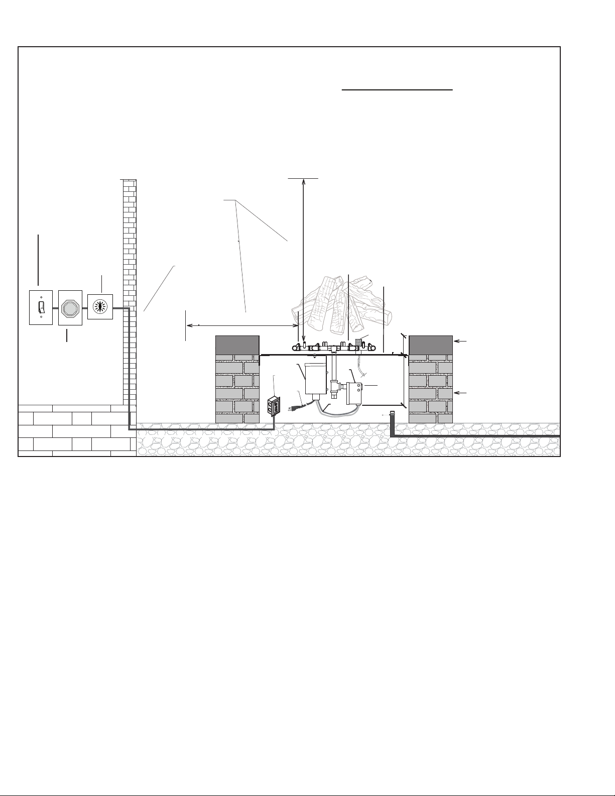
Clearances Diagram .................................................................................................. 8
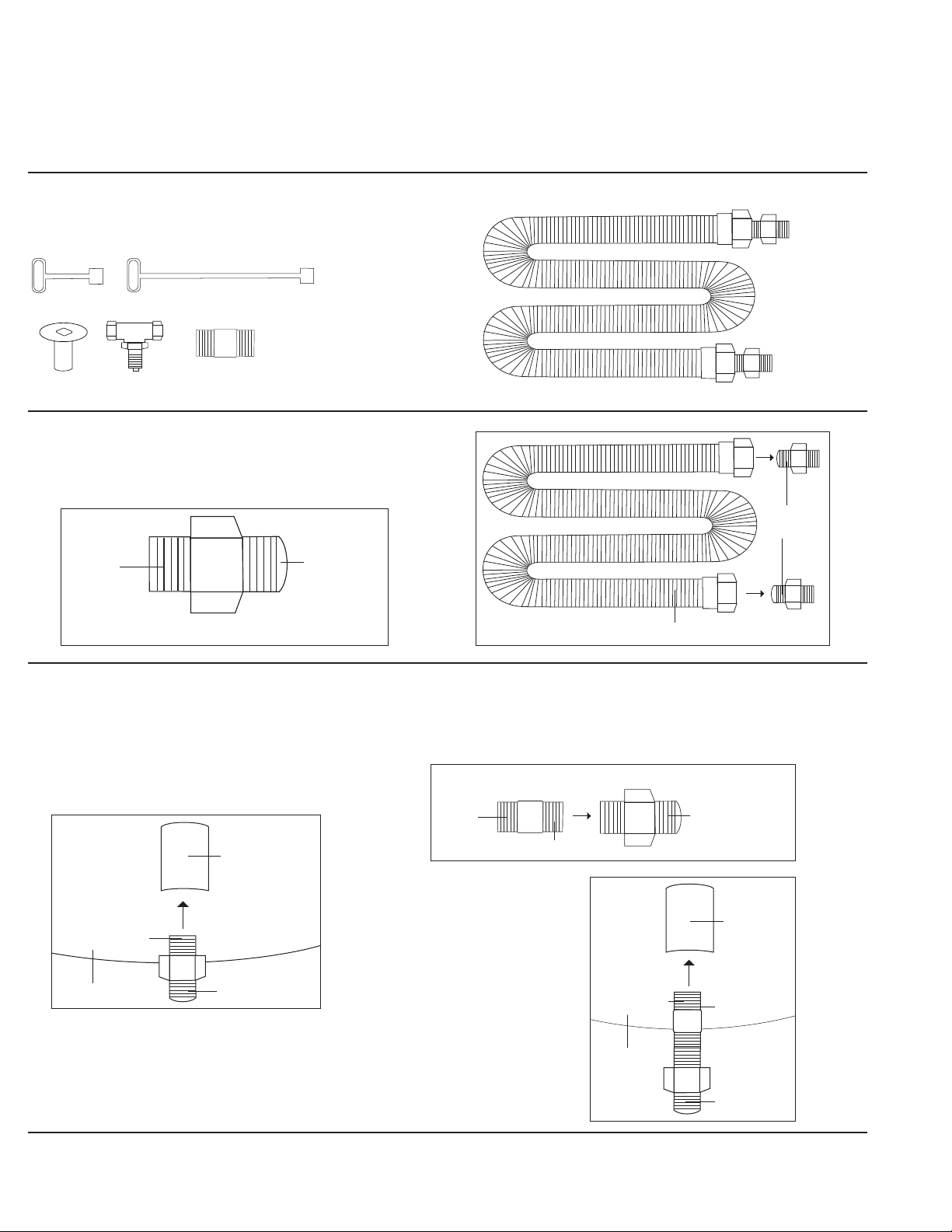
General Burner System Installation ......................................................................... 8
Match Lit System Connection Diagrams... .................................................... .........10
(60K - 120K w/ FLKV12 and 121K - 249K w/ FLKV34FIT180)
Match Lit System Connection Diagrams ....................................................... .........12
(250K - 299K w/ DFLKV34FIT250 and 250K - 299K w/ DFLKV34FIT300)
24 Volt Electronic Ignition System Connection Diagrams .......................... .........14
(60K - 120K w/ FLKV12 and 121K - 249K w/ FLKV34FIT180)
24 Volt Electronic Ignition System Connection Diagrams .......................... .........16
(250K - 299K w/ DFLKV34FIT250 and 250K - 299K w/ DFLKV34FIT300)
Push Button Ignition System Connection Diagrams ............................................. 19
Media Installation ..................................................................................................... 20
Operating Instructions ............................................................................................. 20
FireStorm Steel Gas Log Owner Information and Installation ............................. 21
General Maintenance ............................................................................................... 22
Troubleshooting ........................................................................................................ 23
Warranty ..................................................................................................................... 24
Prop 65 Warning ....................................................................................................... 25
Replacement Parts .................................................................................................... 26
Compliance with the following codes:
1. 2021, 2018, 2015, 2012, and 2009 International Fire Code® (IFC)
2. 2021, 2018, 2015, 2012, and 2009 International Fuel Gas Code® (IFGC)
3. 2018, 2015, 2012 and 2009 Uniform Mechanical Code® (UMC)*
4. 2020, 2015 and 2010 Natural Gas and Propane Installation Code**
**Copyrighted publication of Canadian Standard Association
Compliance with the following standards:
1. ANSI Z21.97/CSA 2.41-2017 Outdoor Decorative Gas Appliances
Product: Outdoor Decorative Gas Fire Pit and Fireplaces
ICC-ES Report PMG-1213
MATCH LIT:
Model # CFB60 NG/LP as match lit
Model # CFB120 NG/LP as match lit
Model # CFB180 NG/LP as match lit
Model # CFB240 NG/LP as match lit
Model # CFB290 NG/LP as match lit
Model # CFBL90 NG/LP as match lit
Model # CFBL110 NG/LP as match lit
Model # CFBL130 NG/LP as match lit
Model # CFBL150 NG/LP as match lit
Model # CFBL190 NG/LP as match lit
Model # CFBL210 NG/LP as match lit
Model # CFBL250 NG/LP as match lit
Model # CFBL270 NG/LP as match lit
Model # CFBL320 NG/LP as matchlit
Model # CFB60 2XL NG/LP as match lit
Model # CFBH120 NG/LP as match lit
Model # CFBH160 NG/LP as match lit
Model # CFBH200 NG/LP as match lit
Model # CFBH240 NG/LP as match lit
Model # CFBH260 NG/LP as match lit
Model # CFBH300 NG/LP as match lit
Model # CFBH340 NG/LP as match lit
Model # CFBH420 NG/LP as match lit
Model # CFBT110 NG/LP as match lit
Model # CFBT170 NG/LP as match lit
Model # CFBT230 NG/LP as match lit
Model # CFBT290 NG/LP as match lit
Model # CFBT350 NG/LP as match lit
Model # CFBT410 NG/LP as match lit
Model # CFBT470 NG/LP as match lit
Model # CFBO180 NG/LP as match lit
Model # CFBO280 NG/LP as match lit
Model # CFBO360 NG/LP as match lit
Model # WTV40 NG/LP as matchlit
Model # WTV60 NG/LP as matchlit
Model # WTV120 NG/LP as matchlit
Model # WTV180 NG/LP as matchlit
24 VOLT PREMIUM ELECTRONIC
IGNITION SYSTEMS - Standard Capacity
Model # CFB60 NG/LP with P24VIKSC
Model # CFB120 NG/LP with P24VIKSC
Model # CFB180 NG/LP with P24VIKSC
Model #CFB240 NG/LP with P24VIKSC
Model # CFB290 NG/LP with P24VIKSC
Model # CFBL90 NG/LP with P24VIKSC
Model # CFBL110 NG/LP with P24VIKSC
Model # CFBL130 NG/LP with P24VIKSC
Model # CFBL150 NG/LP with P24VIKSC
Model # CFBL190 NG/LP with P24VIKSC
Model # CFBL210 NG/LP with P24VIKSC
Model # CFBL250 NG/LP with P24VIKSC
Model # CFBL270 NG/LP with P24VIKSC
Model # CFB60 2XL NG/LP with P24VIKSC
Model # CFBH120 NG/LP with P24VIKSC
Model # CFBH160 NG/LP with P24VIKSC
Model # CFBH200 NG/LP with P24VIKSC
Model # CFBH240 NG/LP with P24VIKSC
Model # CFBH260 NG/LP with P24VIKSC
Model # CFBT110 NG/LP with P24VIKSC
Model # CFBT170 NG/LP with P24VIKSC
Model # CFBT230 NG/LP with P24VIKSC
Model # CFBT290 NG/LP with P24VIKSC
Model #CFBO180 NG/LP with P24VIKSC
Model #CFBO280 NG/LP with P24VIKSC
Model # WTV60 NG/LP with P24VIKSC
Model # WTV120 NG/LP with P24VIKSC
Model # WTV180 NG/LP with P24VIKSC
24 VOLT STANDARD ELECTRONIC
IGNITION SYSTEMS - High Capacity
Model # CFB240 NG/LP with 24VIKHC
Model # CFB290 NG/LP with 24VIKHC
Model # CFB300 NG/LP with 24VIKHC
Model # CFBL210 NG/LP with 24VIKHC
Model # CFBL250 NG/LP with 24VIKHC
Model # CFBL270 NG/LP with 24VIKHC
Model # CFBL320 NG/LP with 24VIKHC
Model # CFBH240 NG/LP with 24VIKHC
Model # CFBH260 NG/LP with 24VIKHC
Model # CFBH300 NG/LP with 24VIKHC
Model # CFBH340 NG/LP with 24VIKHC
Model # CFBH420 NG/LP with 24VIKHC
Model # CFBT230 NG/LP with 24VIKHC
Model # CFBT290 NG/LP with 24VIKHC
24 VOLT STANDARD ELECTRONIC
IGNITION SYSTEMS - Standard Capacity
Model # CFB60 NG/LP with 24VIKSC
Model # CFB120 NG/LP with 24VIKSC
Model # CFB180 NG/LP with 24VIKSC
Model # CFB240 NG/LP with 24VIKSC
Model # CFBL90 NG/LP with 24VIKSC
Model # CFBL110 NG/LP with 24VIKSC
Model # CFBL130 NG/LP with 24VIKSC
Model # CFBL150 NG/LP with 24VIKSC
Model # CFBL190 NG/LP with 24VIKSC
Model # CFB60 2XL NG/LP with 24VIKSC
Model # CFBH120 NG/LP with 24VIKSC
Model # CFBH160 NG/LP with 24VIKSC
Model # CFBH200 NG/LP with 24VIKSC
Model # CFBT110 NG/LP with 24VIKSC
Model # CFBT170 NG/LP with 24VIKSC
Model # CFBO180 NG/LP with 24VIKSC
Model # CFBO280 NG/LP with 24VIKSC
Model # WTV60 NG/LP with 24VIKSC
Model # WTV120 NG/LP with 24VIKSC
Model # WTV180 NG/LP with 24VIKSC
3V BATTERY OPERATED UNITS
Model # CFB60 NG/LP with 3VIK
Model # CFB120 NG/LP with 3VIK
Model # CFB240 NG/LP with 3VIK
Model # CFBL90LP NG/LP with 3VIK
Model # CFBL110LP NG/LP with 3VIK
Model # CFBL130LP NG/LP with 3VIK
Model # CFBL150LP NG/LP with 3VIK
Model # CFBL190LP NG/LP with 3VIK
Model # CFBL210LP NG/LP with 3VIK
Model # CFBL250LP NG/LP with 3VIK
Model # CFB60 2XL NG/LP with 3VIK
Model # CFBH120LP NG/LP with 3VIK
Model # CFBH160LP NG/LP with 3VIK
Model # CFBH200LP NG/LP with 3VIK
Model # CFBH240LP NG/LP with 3VIK
Model # CFBH260LP NG/LP with 3VIK
Model # CFBH300LP NG/LP with 3VIK
Model # CFBH340LP NG/LP with 3VIK
Model # CFBT110LP NG/LP with 3VIK
Model # CFBT170LP NG/LP with 3VIK
Model # CFBT230LP NG/LP with 3VIK
Model # CFBT290LP NG/LP with 3VIK
Model # CFBT350LP NG/LP with 3VIK
Model # CFBT410LP NG/LP with 3VIK
Model # CFBT470LP NG/LP with 3VIK
Model # CFBO180 NG/LP with 3VIK
Model # CFBO280 NG/LP with 3VIK
Model # CFBO360 NG/LP with 3VIK
Model # WTV60 NG/LP with 3VIK
Model # WTV120 NG/LP with 3VIK
Model # WTV180 NG/LP with 3VIK
Model # WTVES120 NG/LP as matchlit
Model # WTVES180 NG/LP as matchlit
Model # WT230 NG/LP as matchlit
Model # WTV350 NG/LP as matchlit
Model # CFBT350 NG/LP with 24VIKHC
Model # CFBT410 NG/LP with 24VIKHC
Model # CFBT470 NG/LP with 24VIKHC
Model # CFBO180 NG/LP with 24VIKHC
Model # CFBO280 NG/LP with 24VIKHC
Model # CFBO360 NG/LP with 24VIKHC
Model # WTV60 NG/LP with 24VIKHC
Model # WTV120 NG/LP with 24VIKHC
Model # WTV180 NG/LP with 24VIKHC

www.Warming-Trends.com | 303 346 2224 | orders@warming-trends.com 5
GENERAL INFORMATION
This Owner’s Guide and Instruction Manual contains critical information for the safe installation and operation of your
You must read this manual in its entirety prior to installation and/or operation.
Failure to follow these instructions may result in property damage, personal injury, or death.
High Capacity (HC) ignitions may be substituted for Standard Capacity (SC) ignitions.
WARRANTY REQUIREMENT:
will void the warranty.
WARNING:
HOT! DO NOT TOUCH.
SEVERE BURNS MAY RESULT.
CLOTHING IGNITION MAY RESULT.
• You ng chil dren should be carefully s upervised when the y are in the a rea of the appliance.
•
on or near the appliance.
• Children and adults should be alerted to the hazards of high surface temperatures and
should stay away to avoid burns or clothing ignition.
WARNING:
technician to inspect the appliance and to replace any part of the control system and any
gas control that has been under water.
WARNING:
DO NOT USE OXYGEN MIXERS WITH YOUR WARMING TRENDS®
property damage, personal injury, or death.
WARNING:
Product is not intended to be used to burn wood or other combustibles. Solid fuels shall
not be burned in the appliance.
WARNING:
or burner. Do not use an alternative fuel.
We strongly recommend our products be installed and serviced by locally licensed professionals. It is the installer’s
responsibility to read the Installation Manual thoroughly before installing or servicing this equipment to ensure a safe
installation and to educate the end user as to proper operation. Warming Trends™ is not responsible for damage
due to improperly installed or operated units. Installers must leave this manual with the end user. Instructions are
updated as needed, and it is the installer or owners’ responsibility to periodically review Warming Trends® website for
applicable updates (www.Warming-Trends.com.) Please keep this manual with your important papers.
24 VOLT PREMIUM ELECTRONIC
IGNITION SYSTEMS - High Capacity
Model # CFB300 NG/LP with P24VIKHC
Model # CFBL320 NG/LP with P24VIKHC
Model # CFBH300 NG/LP with P24VIKHC
Model # CFBH340 NG/LP with P24VIKHC
Model # CFBH420 NG/LP with P24VIKHC
Model # CFBT350 NG/LP with P24VIKHC
Model # CFBT410 NG/LP with P24VIKHC
Model # CFBT470 NG/LP with P24VIKHC
Model # CFBO360 NG/LP with P24VIKHC
Model # WTV120 NG/LP with P24VIKHC
High Capacity (HC) ignitions may be substituted for Standard
Capacity (SC) ignitions.

www.Warming-Trends.com | 303 346 2224 | orders@warming-trends.com
6
CODE REQUIREMENTS
It is the responsibility of the installer to consult with the
local municipality and to FOLLOW ALL LOCAL CODES
When the appliance is for connection to a
conform with local codes, or in the absence
of local codes with the National Fuel Gas
Code, ANSI Z223.1·NFPA54; National Fuel
Gas and Propane Installation Code, CSA
B149.1; or Propane Storage and Handling
Code, CSAB149.2, as applicable.
The appliance when installed, must be
electrically grounded in accordance with
local codes, or in the absense of local
codes, with the National Electrical Code,
ANSI/NFPA 70; or the Canadian Electrical
Code, CSA C22.1, if applicable.
MATCH LIGHT Minimum
Natural Gas 3.5” W.C.
(.8718 Kpa)
7.0” W.C.
(1.7436 Kpa)
Liquid Propane 11.0” W.C.
(2.7399 Kpa)
13.0” W.C.
(3.2381 Kpa)
3V - 3VIK Minimum
Natural Gas 4.5” W.C.
(1.1209 Kpa)
10.0” W.C.
(2.4908 Kpa)
Liquid Propane 11.0” W.C.
(2.7399 Kpa)
13.0” W.C.
(3.2381 Kpa)
STANDARD - 24VIKHC Minimum
Natural Gas 3.0” W.C.
(.7472 Kpa)
5.0” W.C.
(1.2454 Kpa)
Liquid Propane 8.0” W.C.
(1.9927 Kpa)
12.0” W.C
(2.989 (Kpa)
PREMIUM - P24VIKSC,
P24VIKHC
Minimum
Natural Gas 3.5” W.C.
(.8718 Kpa)
14.0” W.C.
(3.4872 Kpa)
Liquid Propane 8.0” W.C.
(1.9927 Kpa)
14.0” W.C.
(3.4872 Kpa)
Gas Inlet Pressures
LOCATION CONSIDERATIONS
All appliances, match lit kits, spark ignition, and electronic
ignition systems are designed and intended for outdoor use
only.
For electronic ignition models, there must be an electrical
shutoff (wall switch or breaker) on the exterior of the appli-
ance or on adjacent structure to allow for emergency shut-
down and maintenance. Distance may be determined by
local code.
All appliances must have a gas shutoff located outside of the
appliance to allow for emergency shutoff and maintenance.
Select a location where the appliance can be attended during
operation. Never leave an operating appliance unattended
or by someone not familiar with its operation or emergency
shutoff locations.
Appliances may create very high temperatures - combusti-
bles must be located far enough away that there is no risk of
ignition.
IMPORTANT: It is recommended that material such as
granite, marble or other dense stone be kept an appropriate
-
er is not responsible for damage to any enclosure material for
any reason.
FIRE PIT CLEARANCES
• 36” horizontally from any combustible structure or
materials.
• Overhead clearance should be a minimum of 120”
from combustible structures or materials.
• Choose a location that allows easy access for installa-
•
to enjoy the appliance while allowing a safe distance
• Always consult with local municipality regarding any
local code requirements.
• See Clearance Diagram on page 8.
The enclosure must be constructed on a stable surface and
must be level.
For models with electronic ignitions, the control/valve box
must be above grade with adequate drainage to prevent
water exposure to the controls inside the box. Additionally,
the weight of the burner system must not be supported by or
rest upon the control valve/box. A plate, pan or other surface
should be used to support the weight of the burner system.
Blocks, bricks, L-brackets, or metal collars can be used to
build a support ledge for the system plate or pan.
A center support (using blocks, bricks or other non-com-
plates and pans over 30” and for rectangular plates or
pans over 40”.
Warming Trends Burners, Ignitions, Media and other Acces-
sories may be installed in Outdoor Fireplaces. The clearances,
materials, venting and construction standards for Outdoor
Fireplaces may be determined by Local or National Codes.
Such Codes may incorporate or defer to the recommenda-
tions or requirements of the Outdoor Fireplace Manufacturer
or the party designing the Fire Place. It is the installer’s respon-
sibility to ensure conformance to applicable local standards.
Gas Inlet Pressures
The installer is responsible for using the correct fuel lines
For systems with electronic ignitions:

www.Warming-Trends.com | 303 346 2224 | orders@warming-trends.com 7
For electronic ignition models requiring power supply – a
The unit may be hardwired or an outdoor NEMA rated
GFCI Receptacle outlet can be installed on the interior of
the enclosure above grade to supply power to system.
Minimum ventilation requirement: Incorporate 1 vent
on at least two opposing sides (2 vents total) at a
minimum size of 18 sq. inches each (Example: 3”x 6” or
larger). Installation of the vents in the mid to lower area
of the enclosure is recommended. Ventilation allows for
heat and/or residual fuel to escape. Failure to properly
vent enclosure may result in the appliance overheating
or explosion. Overheating could lead to heat damage
to internal components. Some enclosures may require
more ventilation based on material, size, and extended
use. Always consult with local municipality regarding
any code requirements.
Ready-to-Finish
Kits come with Fire
Pit Vent Kit (FPVK).
Vents do not come
pre-installed on
Ready-to-Finish Kit
as placement and
installation depends
on veneer. Vents
to be installed by
contractor on site.
any material (gravel, crushed rock, concrete, etc.).
The appliance assembly should be recessed 4”- 6” from the
CONSTRUCTION OF
ENCLOSURE
WARNING:
All appliances must have a gas shutoff
emergency shut off and maintenance.
WARNING:
For electronic ignition models, there must
be an electrical shutoff (wall switch or
or on adjacent structure to allow for
emergency shutdown and maintenance.
Verify correct power supply.
If located on the vessel, key valve should be mounted
below the plate and through the side wall of the vessel. Key
valves may be mounted remotely or on adjacent surfaces.
Always use proper materials and construction for gas sup-
ply, power and enclosure. Materials must be non-combusti-
ble in both initial installations as well as over time.
Some conditions may require deeper recession.
It is the responsibility of the installer to provide proper in-
stallation to allow for easy accessibility for service and/or
repairs. Installer must not build capstone inner ledge over
outer lip of plates or pans (unless access panel door or
alternate access is incorporated). Building capstone inner
ledge over outer edge of plates or pans will impede ac-
cess to system and result in the need to crack or remove
capstones to gain access. Warming Trends is not responsi-
ble for damage to enclosure for any reason whatsoever.
WARNING: These instructions do not
apply to vessels or appliances with self
contained propane gas supply systems.
Appliances or vessels with self contained
propane gas supply systems have
installer or manufacturer. Please consult

www.Warming-Trends.com | 303 346 2224 | orders@warming-trends.com
8
(G)
(D)
(E)
(F)
4"
120"
(A)
- Burner and jets should be
covered by up to 1/2” of media
above jets.
- 12 - 13" Minimum clearance
below plate required for
electronic ignition
(H)
36"
(C)
(B)
10"
(I)
CROSSFIRE™
Brass Burner Aluminum
Plate/Pan
Fire Pit Cavity Components
(A) GFCI Outlet
(B) Location for remote receiver (optional)
(C) Pigtail plug included for easy installation
(D) Electronics Box (Houses 120V - 24V Transformer)
(E) 24V Power from Transformer to Gas Valve
(F) Gas Valve / Control Box
(G) Pilot Assembly
(H) Gas Valve Supply IN
(I) Gas Stub from source
110V\120V
Power Line
Required 18 sq.
inches of venting, or
equivalent, on
OPPOSING sides of
fire pit. (36 inches total.)
Enclosure constructed
of all non-combustible
materials
CapstoneCapstone
Plate/Pan
Plate/Pan
EMERGENCY
STOP
PUSH
Emergency
Stop Push
Button
(Optional)
2 hr or 12 hr
Dial Timer
(Optional)
External power switch
required for all
electronic ignitions
(other than battery
operated ignitions)
Clearances
from combustible
structure or
materials
GENERAL INSTALLATION INSTRUCTIONS
FIRE PIT CLEARANCES DIAGRAM
1. Verify gas supply matches burner type.
2.
imum and maximum pressures. Consult Gas Inlet
Pressures on page 6.
3. Purge gas lines of air, water and debris.
4. Perform all leak tests with leak detector or leak reactant
on main gas supply and repair leaks as necessary. Turn
off gas supply.
5. For models that include electronic ignitions, be sure to
following all local codes.
6.
7. Make sure the key turns in the key valve before in-
stalling. Use only your hand to turn the gas key valve.
Never use tools. If the key valve will not turn by hand,
don’t try to repair it. Force or attempted repair may
8. Refer to Connection Diagrams starting on page 10
for applicable gas connections.
9. Position burner safely with access to all gas connec-
avoide damage.
10. Turn on gas supply to perform repeat leak tests on
main gas supply and all connections to appliance and
repair as needed.
11. Do not use appliance if there is evidence of leaking gas. If
leak is suspected, turn off main gas supply immediately.
to gas use that is resistant to all gases. Apply joint
only and DO NOT USE ON FLARED END OF FLARED
FITTINGS. Be sure to tighten every joint securely.
Ignition systems are recommended on any burner
over 300K BTUs. If you are lighting manually be sure
to maintain a minimum safe distance to avoid property
damage, personal injury, or death. Please refer to match
lit instructions.
Vertical clearance of 120” from burner to combustible structure or materials is
required. Horizontal or lateral clearance of 36” between edge of burner and
combustible structure or materials is required.

www.Warming-Trends.com | 303 346 2224 | orders@warming-trends.com 9
equipped with an appliance gas pressure regulator, the
appliance and its individual shutoff valve must be discon-
nected from the gas supply piping system during any
pressure testing of that system at test pressure in excess
of ½ psi (3.5kPa).
The appliance must be isolated from the gas supply pip-
ing system by closing its individual manual shutoff valve
during any pressure testing of the gas supply piping sys-
tem at test pressures equal to or less than ½ psi (3.5 kPa).
12. Ignite burner. See applicable ignition instructions
within Operating Instructions, page 20.
13. Electronic ignitions can either be hard wired into main
-
let/receptacle per local codes. The electrical supply
-
ternal to the pit. Remote controls, emergency stops,
and dial timers are optional add-ons.
14. Once appliance is lit, perform leak test on all gas con-
nections and repair as needed.
15. Turn off appliance and allow to cool.
16. Set appliance into properly constructed, level, non-com-
bustible enclosure. The enclosure must be on a stable
surface. The weight of the appliance must be supported
by the plate or pan and not by any control box or gas
valve. Blocks, bricks, metal collars or L-brackets can be
used to build a support ledge for the system plate or
pan. Control boxes and gas valves must be above grade
with adequate drainage to prevent water damage.
Installer is responsible for making sure there is enough
space in the cavity for any electronics and piping. The
any material (i.e. gravel, crushed rock, concrete, etc).
wind and to allow coverage of burner. See Clearances
Diagram on previous page.
17. To allow for regular maintenance, any capstone
materials should not overhang the interior edge of
Clearances Diagram on page 8 for
placement. Warming Trends® is not responsible for
any damages to the capstone.
18. Venting is required to avoid heat damage to inter-
pooling. Incorporate 1 vent on at least two opposing
sides (2 vents total) at a minimum size of 18 sq. inches
each for 36” total (example: 3”x 6”). Installation of
the vents in the mid to lower area of the enclosure is
recommended. Some enclosures may require more
ventilation based on material, size, and extended use.
Ready-to-Finish Kits come with Fire Pit Vent Kit (FPVK).
Vents do not come pre-installed on Ready-to-Finish.
Fire Pit Vent Kits must be installed on site.
19.
etc.) approved for use with high temperatures that
-
tures. Never use any material for media that is non-po-
rous and holds moisture such as gravel, pebbles, river
rock, etc. Such material, when heated, may cause the
trapped moisture to boil, fracture unexpectedly and/
or explode and which could cause personal injury,
damage or death.
20. To avoid dust and clogs getting into the system, do not
dump the media over the burner. Place the media onto
the plate or pan. Burner should be covered by ap-
proved media up to ½” above the jets. Media may be
-
sive media coverage may cause back pressure and
-
sion which could cause property damage, personal
injury, or death.
21. Do not cover the ignition pilot assembly or wind cage
more than halfway with any form of media. Do not
place ceramic logs too close to the pilot assembly as
this may cause excessive heat and system failure that
is not covered by warranty.
22. Ceramic log sets must be pre-treated before use to
avoid breaking or crumbling. Burn logs for 15 minutes,
then leave untouched to cool for at least one hour before
moving them again, or they could break or crumble.
23.
24. Review instruction manual with end user and instruct end
WARNING: Improper installation, adjustment
alteration, service or maintenance can cause
property damage, personal injury or loss of
life. Refer to the owner’s information manual provided
with this appliance. Installation and service must be
gas supplier.
WARNING: Do not store or use gasoline, or
of this or any other appliances.
An LP-cylinder not connected for use shall not be stored
in the vicinity of this or any other appliance.
AVERTISSEMENT: Une installation, un
cause de blessures ou de dommages. Veuillez lire
attentivement les instructions d’installation, d’utilisation
AVERTISSEMENT: Ne pas entreposer ni
utiliser de l’essence ni d’autres vapeurs ou
de tout autre appareil.
voisinage de cet appareil ou de tout autre appareil.
The following label has been provided with the appliance.
appliance.

www.Warming-Trends.com | 303 346 2224 | orders@warming-trends.com
10
MATCH LIT SYSTEM CONNECTION DIAGRAMS
60K - 249K BTU Systems
60K - 120K FLKV12 (Follow steps 1 - 6)
121K - 249K FLKV34FIT180 (Follow steps 1 - 6, including 3A)
1. Locate FLKV12 (or FLKV34FIT180)
Parts include Whistle-Free Flex Line, key valve, escutcheon
plate, keys, and FIT180 (FLKV34FIT180 ONLY)
(FLKV12 and FLKV34FIT180)
3. Connect to Coupling
(FLKV12) Connect one of your ½”
Flared Fittings removed in Step 2
to the ½” coupling located on the
bottom of the aluminum plate with
3A. Connect to FIT180, then to Coupling
(FLKV34FIT180) Connect one ¾” Flared Fitting removed
Then, connect
into the coupling
located on the
bottom of the
aluminum plate.
Tighten.
3” Key
Escutcheon Key Valve
FIT180 Kit: ½” x 2” Nipple
Included with FLKV34FIT180 ONLY
12” Key
STEP 1 - FIT180
Whistle-Free Flex Line
Flared
Fitting
Whistle-Free Flex Line
Plate
Plate
Coupling
Coupling
½” Flared Fitting
Apply thread
sealant here
Apply thread
sealant here
STEP 3
Use inside threads
of Flared Fitting
FIT180 ¾” Flared Fitting
Apply thread sealant here
¾” Flared
Fitting
FIT180
Leave this Connection Diagram with end user.
STEP 3
Flared Fitting
Flared End
Thread
sealant is
applied
to this
end only
throughout
instructions

www.Warming-Trends.com | 303 346 2224 | orders@warming-trends.com 11
MATCH LIT SYSTEM INSTALLTION 60K - 249K BTU Systems CONTINUED
(FLKV12 and FLKV34FIT180) Connect
the Whistle-Free Flex Line to the
Flared Fitting previously attached to
the coupling on the bottom of the
aluminum plate.
(FLKV12 and FLKV34FIT180)
Connect the Whistle-Free Flex Line
to the Flared Fitting that is now
connected to the Key Valve.
Connect Escutcheon Plate to Key
Valve through vessel wall. Tighten.
Flared Fitting
Coupling
Flared Fitting
Whistle-Free Flex Line
Key
WALL
GAS LINE IN FLKV12 SHOWN
Escutcheon
Plate
Plate
Coupling
Flared Fitting
Whistle-Free
Flex Line
5. Locate 2nd Flared Fitting and Connect to Key Valve
(FLKV12 and FLKV34FIT180) Locate the second Flared
Fitting removed in Step 2 and connect into the Key
Tighten.
STEP 5
Key ValveFlared Fitting
Apply thread
sealant here
Key Valve
Shown
with
FIT180

www.Warming-Trends.com | 303 346 2224 | orders@warming-trends.com
12
MATCH LIT SYSTEM CONNECTION DIAGRAMS
250K - 299K BTU Systems
250K - 299K FLKV34FIT250 (Follow steps 1 - 6)
250K - 299K FLKV34FIT300 (Follow steps 1 - 6, including 3A)
1. Locate DFLKV34 and FIT250 OR DFLKV34 and FIT300
Parts include two Whistle-Free Flex Lines, key valve,
escutcheon plate, keys, and FIT250 Kit (DFLKV34FIT250
ONLY) or FIT300 Kit (DFLKV34FIT300 ONLY)
3” Key
Escutcheon Key Valve
FIT250 Kit: (1) ¾” x 3” Nipple
(1) ¾” x ½” MM Reducer Fitting
(2) ¾” Tees
Included with DFLKV34FIT250 ONLY
FIT300 Kit: (2) ¾” x 3” Nipple
(2) ¾” Tees
Included with DFLKV34FIT300 ONLY
12” Key
Whistle-Free Flex Lines
STEP 1- FIT250
STEP 1- FIT250
STEP 1- FIT250
3. Connect FIT250 to
Coupling
(DFLKV34FIT250)
Connect ½” x ¾”
Reducing Fitting to
½” Coupling located
on the bottom of the
aluminum plate.
Then connect ¾” Tee
to ½” x ¾” Reducing
Fitting.
3A. Connect FIT300 to
Coupling
(DFLKV34FIT300)
Connect ¾” x 3”
Nipple to ¾” Coupling
located on the bottom
of the aluminum plate.
Then connect ¾” Tee
to ¾” x 3” Nipple.
Flared
Fitting
Whistle-Free Flex Line
Plate
FIT300 (¾” x 3”
Nipple)
FIT300 (¾” Tee)
Coupling
Plate
FIT250 (½” x ¾”
Reducing Fitting)
FIT250 (¾” Tee)
Coupling
Apply thread
sealant here
Apply thread
sealant here
Apply thread
sealant here
Apply thread
sealant here
STEP 3
Flared Fitting
Flared End
Thread
sealant is
applied
to this
end only
throughout
instructions

www.Warming-Trends.com | 303 346 2224 | orders@warming-trends.com 13
MATCH LIT SYSTEM INSTALLTION 250K - 299K BTU SYSTEMS CONTINUED
4. Connect Flared Fittings to ¾” Tee
(DFLKV34FIT250 and DFLKV34FIT300)
Connect Flared Fittings to ¾” Tee.
5. Connect FIT Kit to Key Valve and
Flared Fittings
(DFLKV34FIT250 and DFLKV34FIT300)
Connect ¾” x 3” Nipple (FIT250 or
FIT300) to Key Valve.
Then connect the ¾” Tee (FIT250 and
FIT300) to the connection just made.
Connect ¾” Flared Fittings to the ¾” Tee.
Key Valve Connection
(DFLKV34FIT250 and DFLKV34FIT300)
Connect ends of ¾” Whistle-Free Flex
Lines to Flared Fittings connected to
the aluminum plate and Coupling.
Then connect available ends of the
Whistle-Free Flex Lines to the Key
Valve Connection.
Connect Escutcheon Plate to Key Valve
through vessel wall. Tighten.
STEP 5
Plate
Coupling
FIT250 (½” x ¾” Reducing Fitting)
or FIT300 (¾” x 3” Nipple)
FIT250 or FIT300
(¾” Tee)
Flared FittingFlared Fitting
Apply thread
sealant here
Apply thread
sealant here
Key Valve
FIT250 or
FIT300
(¾” Tee)
FIT250 or FIT300
(¾” x 3” Nipple)
Apply thread
sealant here
Apply thread
sealant here
Apply thread
sealant here
Whistle-Free Flex Line Whistle-Free Flex Line
Plate
GAS LINE IN
Key Escutcheon
Coupling
FIT250 (½” x ¾” Reducing Fitting)
or FIT300 (¾” x 3” Nipple)
FIT250 or FIT300
(¾” x 3” Nipple)
Key Valve
FIT250 or
FIT300
(¾” Tee)
Flared
Fitting
Flared
Fitting
WALL
Flared Fitting
Flared Fitting

www.Warming-Trends.com | 303 346 2224 | orders@warming-trends.com
14
24 VOLT ELECTRONIC IGNITION SYSTEM
CONNECTION DIAGRAMS
60K - 249K BTU Systems
60K - 120K 12 (Follow steps 1 - 6)
121K - 249K FLKV34FIT180 (Follow steps 1 - 6, including 3A)
(FLKVFIT180) easier.
Flared
Fitting
Whistle-Free Flex Line
1. Locate FLKV12
Parts include Whistle-Free Flex Line, key valve, escutcheon
plate, keys, and FIT180 (FLKV34FIT180 ONLY)
3” Key
Escutcheon Key Valve
FIT180 Kit: ½” x 2” Nipple
Included with FLKV34FIT180 ONLY
12” Key
STEP 1 - FIT180
Whistle-Free Flex Line
3. Connect to Coupling
(FLKV12) Connect one ½” Flared Fittings
removed in Step 2 to Gas Valve.
Plate
3A. Connect to FIT180, then to Coupling
(FLKV34FIT180) Connect one ½” Flared
STEP 3
Use inside threads
of Flared Fitting
FIT180 ¾” Flared Fitting
Apply thread sealant here
STEP 3D
Plate
Coupling
Apply thread
sealant here
Flared
Fitting
24 Volt IgnitionDrip
Leg
STEP 4D
Coupling
Apply thread
sealant here
Flared Fitting
24 Volt IgnitionDrip
Leg
STEP 3
Flared Fitting
Flared End
Thread
sealant is
applied
to this
end only
throughout
instructions

www.Warming-Trends.com | 303 346 2224 | orders@warming-trends.com 15
24 VOLT ELECTRONIC IGNITION SYSTEM INSTALLATION 60K - 249K BTU SYSTEMS CONTINUED
4. Locate 2nd Flared Fitting and Connect to Key Valve
(FLKV12 and FLKV34FIT180) Locate the other Flared
Fitting removed in Step 2 and connect into the Key
Tighten.
5. CONNECT FLEX LINE TO
IGNITION AND KEY VALVE
(FLKV12 and FLKV34FIT180)
Connect Whistle-Free Flex Line
to Flared Fitting connection at
ignition and then to Key Valve/
FIT180 connection in Step 5.
Connect Escutcheon Plate to
Key Valve through vessel wall.
Tighten.
6. CONNECT ELECTRICITY
(FLKV12 and FLKV34FIT180)
Plug ignition into
three prong, above
grade, NEMA Rated,
GFCI electrical outlet
or have electrician
hardware ignition
into transformer.
STEP 5
Key ValveFlared Fitting
Apply thread
sealant here
STEP 6D
Plate
Coupling
24 Volt Ignition
Whistle-Free
Flex Line
Drip
Leg
Flared
Fitting
Flared Fitting
GAS LINE IN
Key Escutcheon
Key Valve
WALL

www.Warming-Trends.com | 303 346 2224 | orders@warming-trends.com
16
1. Locate DFLKV34 and FIT250 OR DFLKV34 and FIT300
Parts include two Whistle-Free Flex Lines, key valve,
escutcheon plate, keys, and FIT250 Kit (DFLKV34FIT250
ONLY) or FIT300 Kit (DFLKVFIT300 ONLY)
3” Key
Escutcheon Key Valve
FIT250 Kit: (1) ¾” x 3” Nipple,
(1) ¾” x ½” MM Reducer Fitting,
(2) ¾” Tees
Included with DFLKV34FIT250 ONLY
FIT300 Kit: (2) ¾” x 3” Nipple,
(2) ¾” Tees
Included with DFLKV34FIT300 ONLY
12” Key
Whistle-Free Flex Lines
STEP 1- FIT250
STEP 1- FIT250
STEP 1- FIT250
Flared
Fitting
Whistle-Free Flex Line
24 VOLT ELECTRONIC IGNITION SYSTEM
CONNECTION DIAGRAMS
250K - 300K+ BTU Systems
250K - 299K 250 (Follow steps 1 - 8)
300K+ 300 (Follow steps 1 - 8, including 3A)
3. Connect to Coupling
(DFLKV34FIT250) Connect ½” x ¾” Reducing Fitting
to Gas Valve
3A. Connect to Coupling
(DFLKV34FIT300) Connect ¾” x 3” Nipple to
Gas Valve
Plate
Coupling
Apply thread
sealant here
FIT300 (¾” x 3” Nipple)
24 Volt Ignition
STEP 3c
Plate
Coupling
Apply thread
sealant here
FIT250 (½” x ¾”
Reducing Fitting)
24 Volt IgnitionDrip
Leg
Drip
Leg
STEP 3
Flared Fitting
Flared End
Thread
sealant is
applied
to this
end only
throughout
instructions

www.Warming-Trends.com | 303 346 2224 | orders@warming-trends.com 17
4. Connect Flared Fittings to ¾” Tee
(DFLKV34FIT250 and
DFLKV34FIT300) Connect ¾” Tee
to ½” x ¾” Reducing Fitting (FIT250)
or ¾” x 3” Nipple (FIT300).
Then connect Flared Fittings to
¾” Tee.
(DFLKV34FIT250 and
DFLKV34FIT300)
24 VOLT ELECTRONIC IGNITION SYSTEM INSTALLATION 250K - 290K BTU SYSTEMS CONTINUED
Plate
Coupling
3/4” Tee
(FIT250 or
FIT300)
Flared Fitting
Flared Fitting
Apply thread
sealant here
Apply thread
sealant here
FIT250 (½” x ¾”
Reducing Fitting) or
FIT300 (¾” x 3” Nipple)
24 Volt IgnitionDrip
Leg
Plate
Coupling
3/4” Tee
(FIT250 or
FIT300)
Flared Fitting
Whistle-Free
Flex Line
Flared Fitting
FIT250 (½” x ¾”
Reducing Fitting) or
FIT300 (¾” x 3” Nipple)
24 Volt IgnitionDrip
Leg
Whistle-Free
Flex Line
Apply thread
sealant here

www.Warming-Trends.com | 303 346 2224 | orders@warming-trends.com
18
24 VOLT ELECTRONIC IGNITION SYSTEM INSTALLATION 250K - 290K BTU SYSTEMS CONTINUED
6. Connect FIT Kit to Key Valve and
Flared Fittings
(DFLKV34FIT250 and DFLKV34FIT300)
Connect ¾ ” x 3” Nipple (FIT250 and
FIT300) to Key Valve.
Then connect the ¾ ” Tee (FIT250 or
FIT300) to the connection just made.
Connect ¾ ” Flared Fittings to the ¾ ” Tee.
Key Valve
FIT250 or
FIT300
(¾ ” Tee)
FIT250 or FIT300
(¾ ” x 3” Nipple)
Apply thread
sealant here
Apply thread
sealant here
Apply thread
sealant here
Coupling and
Key Valve
Connection
(DFLKV34FIT250 and
DFLKV34FIT300)
Connect ends of 3/4”
Whistle-Free Flex
Lines to Flared Fittings
connected to the 24
Volt Ignition. Then
connect available
ends of the Whistle-
Free Flex Lines to the
Key Valve Connection.
Connect Escutcheon
Plate to Key Valve
through vessel wall.
Tighten.
Whistle-Free Flex Line
Plate
GAS
LINE
IN
Key
Escutcheon
Coupling
FIT250 (½ ” x ¾ ”
Reducing Fitting)
or FIT300 (¾ ” x 3”
Nipple)
FIT250 or FIT300
(¾ ” x 3” Nipple)
Key Valve
FIT250 or
FIT300
(¾ ” Tee)
Flared
Fitting
Flared
Fitting
Flared
Fitting
Flared
Fitting
24 Volt IgnitionDrip Leg
8. CONNECT
ELECTRICITY
(FLKV12 and
FLKV34FIT180)
Plug ignition into
three prong, above
grade, NEMA Rated,
GFCI electrical outlet
or have electrician
hardware ignition
into transformer.
WALL
Flared Fitting
Flared Fitting

www.Warming-Trends.com | 303 346 2224 | orders@warming-trends.com 19
4. Test without Gas
Test Spark Igniter and Push
Button Module WITHOUT gas,
making sure spark arcs from
electricity to jet.
5. Test with Gas
Burner should light within 5
seconds or a few clicks.
2. Install Push Button Module
into Mounting Bracket
Unscrew Button Cover.
Remove plastic Nut.
Insert Washer #1 onto the
button stem.
Insert Push Button Stem
through mounting bracket
hole.
Insert Washer #2.
Put on plastic Nut and turn
until Push Button Control has
been secured to mounting
bracket.
Insert AAA Battery into Button
Stem.
Screw on Button Cover.
Push Button
Module
Key Valve
Button Stem
Washer #1
Washer #2
Nut
AAA Battery
Button Cover
Mounting Bracket
3. Connect Spark Igniter Wires
Crimp Spark Igniter Wires,
then slide crimped wires on
to connections using needle
nose pliers. Be careful not to
break connectors. Wires can
go in either connection.
Push Button
Module
Spark Igniter
Wires
Key Valve
Mounting Bracket
Jet
Drill
Here
Spark
Igniter
Stem
.125”
Plate
CROSSFIRE
Brass Burner
PUSH BUTTON IGNITION SYSTEM
CONNECTION DIAGRAMS Up to 300K BTU Systems
1. To place the Spark Igniter in the
proper position, installer will
need to drill a hole in the plate.
Measure where to drill hole by
holding tip of Spark Igniter no further
than .125” away from inside edge
of jet. Drill hole where base of spark
igniter sits. Thread wires through
drilled hole and pull until Spark
Igniter bracket is in place on plate.
Screw Spark Igniter to plate.
If the distance to the jet is greater than .125”, you can adjust the position by gently bending the spark ignitor by the stem.
far away or too close to the jet, you will not get a strong enough spark to light the burner.

www.Warming-Trends.com | 303 346 2224 | orders@warming-trends.com
20
MEDIA INSTALLATION
Only use approved decorative media (glass, lava rock,
ceramic log sets, etc.) that have been manufactured for
Media must be ½” or larger in size to prevent media from
jets. Use approved media only. To avoid dust and clogs get-
ting into the system, do not dump the media over the burner.
Place the media onto the plate or pan.
Burner should be covered by approved media up to ½”
above the jets. Media may be positioned so that jet tips or
barrels are visible. PLEASE NOTE - covering jets by more
than ½” of media may create back pressure and gas
-
ty damage, personal injury, or death.
pattern will be affected by any media coverage over gas
When using electronic ignition systems please pay par-
ticular attention to keeping media away from the pilot
assembly area and/or away from wind screen of pilot
assembly. Incorrect media installation that blocks pilot
thermal sensor and/or a delay in main burner ignition.
The appliance is designed to use approved media that is
correctly installed over the burner to achieve proper com-
bustion. Use of any media outside of the approved media
may void warranty and affect proper operations.
feature per instructions
provided by manufacturer.
DO NOT DUMP MEDIA
ON THE JETS. Apply media
by pouring media around
media towards the gas jet
does not fall into the gas jet
For All Electronic Ignition Systems: Keep pilot assembly
screen free and clear of all media. Media should be piled no
more than halfway up screen only (not over full amount of
-
For Ceramic Log Sets:
Place logs on top of lava
rock or media base ac-
cording to preference and
electronic ignition systems
- do not block, cover or
obstruct pilot assembly.
Blocking, covering or placing ceramic logs too close to
pilot may cause excessive heat on pilot causing system to
fail. This is not covered under warranty.
OPERATING INSTRUCTIONS
Keep the area clear and free from combustible materials,
wood, paper, clothing, food material, should be kept away
interfere with safe operation. If there are any questions as
to clearances, refer to CLEARANCES DIAGRAM in your
-
have in an unpredictable manner. If conditions exist, turn
the potential of thermal spalling. This process may occur
when media is wet and moisture gets trapped inside of
the material due to rapid temperature differences. When
this happens the media has the potential to crack or pop
when lighting in high humidity or moisture. After igniting,
allow 30 minutes to dry out the media, and monitor from
a distance until all popping has ceased before fully enjoy-
TURNING ON YOUR MATCH LIT SYSTEM
1. STOP! Read all the safety information.
2. Any cover must be removed prior to operation of burn-
er or appliance and must remain off during operation.
-
ately. After leaving the area, call your gas supplier
-
cause property damage, personal injury or death.
3.
supply to the appliance is open. Do not open your
key valve or gas control valve at this time.
4.
any accumulated leaves or other combustible debris.
5. Locate key valve or gas control valve controlling gas
supply to your appliance.
6. Locate the closest jet tip on the exterior of the burner
that can be easily accessed while operating key valve
or gas control valve without reaching across other jets
Other manuals for CROSSFIRE CFB60 NG
1
This manual suits for next models
81
Table of contents
Other Warming Trends Outdoor Fireplace manuals
Popular Outdoor Fireplace manuals by other brands

Target
Target GAD15300T Assembly instructions

Endless Summer
Endless Summer GAD1499M owner's manual

Landmann
Landmann Ball o fire 28923 Assembly and use instructions

Landmann
Landmann Hartford 25805 Assembly and use instructions

Necessories
Necessories GRAND FIREPLACE Assembly instructions

Bond
Bond 50481 manual

Endless Summer
Endless Summer GAD1393SP owner's manual

Charmate
Charmate CM140-031 manual

BlueRhino
BlueRhino Home WAD613T owner's manual

StoneAge
StoneAge Square Fire Pits Installation and operating instructions

HAMPTON BAY
HAMPTON BAY OFW994FRA-HD Use and care guide

BlueRhino
BlueRhino UniFlame WAD794SP owner's manual