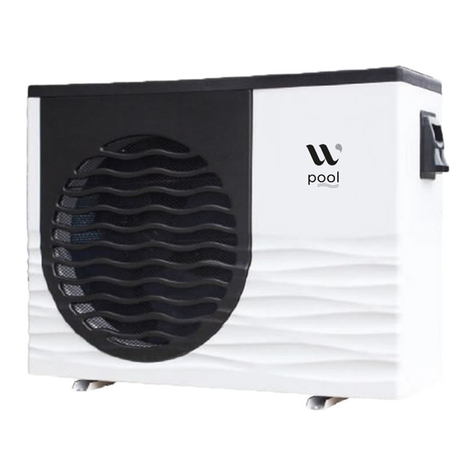
WarmPool WP120 User manual

~ 1 ~
Installation and operation manual WP

~ 2 ~
Installation and operation manual WP
1. Warning
First and foremost, check the condition of your heat pump as soon as you receive it,
write any reservations you have about its state on the delivery note if you have any
doubts or a problem and send a registered letter to your installer or directly to the
manufacturer within 48 hours. After this period, no claim will be accepted.
1.1 Important information
To properly install your heat pump, read this manual carefully. We will not be liable
for any injury to persons or damage to the machine due to any errors that might occur
during installation.
-
The installation of this heat pump must be carried out by qualified personnel,
-
This heat pump meets the manufacturing and communication standards defined by
FPP's DTP10 and NFPAC,
-
The maintenance of this heat pump must be carried out as set out in this manual,
-
Only use original spare parts supplied by the manufacturer,
-
Failure to follow these instructions or the information in this manual will void the
heat pump's guarantee.
2. Your heat pump
2.1 Main features
Your heat pump must not be used for any purpose other than to HEAT your pool. Its
choice was determined following a personalized heat budget and it cannot be used for
other pools until a new heat budget has been carried out.
Your heat pump is one of the most efficient and environmentally friendly heaters,
using R32 gas.

~ 3 ~
Installation and operation manual WP
* Test carried out at an air temperature of 27°C, with the same temperature difference and water
as at 15°C.
** Test carried out at an air temperature of 15°C, with an inlet water temperature of 26°C and an
outlet water temperature of 28°C to define the water flow, heating capacity and power
consumption, according to FPP standards.
*** Test carried out at an air temperature of 35°C, with an inlet water temperature of 30°C and
an outlet water temperature of 29°C.
2.2 Technical characteristics
MODEL
WP120 Inverter
WP120 Inverter Tri
WP140 Inverter
WP140 Inverter Tri
Pool size
Maxi
120m³
120m³
140m³
140m³
Heating capacity *
kW
4.6~19.5
4.6~19.5
5.7~24.2
5.7~24.2
Power consumption *
kW
0.37~3.94
0.37~3.94
0.46~4.8
0.46~4.8
COP *
12.43~4.95
12.43~4.95
12.39~5.04
12.39~5.04
Rated current
A
3.5~15.9
1.3~5.8
3.8~18.4
1.5~6.9
Heating capacity **
kW
3.84~15.4
3.84~15.4
4.68~19.9
4.68~19.9
Power consumption **
kW
0.6~3.81
0.6~3.81
0.72~4.74
0.72~4.74
Cooling capacity ***
kW
0.62~6.87
0.62~6.87
0.74~8.3
0.74~8.3
Cooling power
consumption ***
kW
0.45~4.15
0.45~4.15
0.52~5.1
0.52~5.1
EER ***
1.33~1.65
1.33~1.65
1.42~1.63
1.42~1.63
Casing material
ASA
ASA
ASA
ASA
Controller
Touch screen display, remote control + WIFI module
Gas
R32
R32
R32
R32
Heat exchanger
Titanium twist
Titanium twist
Titanium twist
Titanium twist
Compressor
Rotary Mitsubishi
Rotary Mitsubishi
Rotary Mitsubishi
Rotary Mitsubishi
Number of fans
1
1
2
2
Fan rotation speed (PRM)
T/mn
600-900
600-900
400-800
400-800
Mode
Cooling / Heating /
Auto
Cooling / Heating /
Auto
Cooling / Heating /
Auto
Cooling / Heating /
Auto
Operating range
-15℃~ 43℃
-15℃~ 43℃
-15℃~ 43℃
-15℃~ 43℃
Noise level at 1 m
dB(A)
45~56
45~56
46~57
46~57
Power supply
Mono 220-
240V/50HZ
Tri 380-400V/50HZ
Mono 220-
240V/50HZ
Tri 380-400V/50HZ
Throttling
EEV
EEV
EEV
EEV
Water volume
m3/H
6.6
6.6
8.6
8.6
Unit dimension
mm
1161/490/868
1161/490/868
1161/470/1274
1161/470/1274
Carton dimension (l/L/h)
mm
1210/510/880
1210/510/880
1070×459×1300
1070×459×1300
Net weight / Gross weight
kg
93 / 108
93 / 108
114 / 130
114 / 130
All parts guarantee
5 ans
5 ans
5 ans
5 ans

~ 4 ~
Installation and operation manual WP
2.3 Dimension of swimming pool heat pump WP120
Inverter / WP120Tri Inverter
2.4 Dimension of swimming pool heat pump WP140
Inverter / WP140Tri Inverter

~ 5 ~
Installation and operation manual WP
3. Installation et connections
3.1 Installation
Your heat pump and your pool pump must be installed close to each other.
Your heat pump must be placed outdoors and must follow the minimum spacings
shown on the connection diagram.
Your heat pump should be level and at least 15 cm above the ground. We recommend
you use blocks and drain the condensation into a sump (which can be covered with
gravel).
If any of these recommendations are not followed or are not applicable, please contact
the manufacturer to make sure that the installation performed or to be performed will
not affect the proper functioning of your heat pump.
Using your heat pump will necessarily create condensation (up to several liters of
water per hour). This is not a leak.

~ 6 ~
Installation and operation manual WP
3.2 Hydraulic connection
Before carrying out any work, remember it is vital that all the valves are closed.
As you can see from the connection diagram, you need to install a BYPASS valve (if you
do not already have one) between the filtration system and the water treatment system
(or discharge).
Upstream of this BYPASS, an OUT pipe with a shut-off valve will be connected to the
water inlet of the heat pump and a RETURN pipe with a shut-off valve will be connected
to the water outlet of the heat pump.
Use the PVC connectors provided in the accessory kit to connect the hoses to the heat
pump. On the pump side, fasten the supplied fittings using Teflon tape to ensure a good
seal.
Important: Before filling the pump with water, we recommend washing/rinsing
the filter.
3.3 Electrical connection
Important: The electrical connection of your heat pump must be carried out by
someone qualified to do it. Check that the cable supplying the machine room is
rated for the additional current required by the pump.
The heat pump must be powered from a separate D-curve circuit breaker which may be
either on the main electrical panel fitted with a differential circuit breaker or on an
independent panel connected to the main switchboard, with a differential circuit
breaker. If this is not the case add a differential circuit breaker to the heat pump's
independent panel.
Model
Supply
Circuit breaker rating
D-curve
Cable cross-section as a function of
the distance between the circuit-
breaker and the heat pump
< 10m 10 to 15m > 15m
WP120 Inv.
Single phase 230V
20 Amps
3G2.5
mm2
3G2.5
mm2
3G6
mm2
WP140 Inv.
Single phase 230V
25 Amps
3G2.5
mm2
3G2.5
mm2
3G6
mm2
WP120 Tri
Inv.
Three-phase 380-
400V
20 Amps
5G2.5
mm2
5G2.5
mm2
5G6
mm2
WP140 Tri
Inv.
Three-phase 380-
400V
25 Amps
5G2.5
mm2
5G2.5
mm2
5G6
mm2
Unscrew the knob to access the electrical connection.

~ 7 ~
Installation and operation manual WP
4. Start-up
a) Checking the valves
The BYPASS valve must be fully open.
The inlet and outlet water valves must be closed.
b) Clean the filter
c) Valve settings
Open your valves following the order and setting recommended below, and check for
water leaks.
-
Set the BYPASS valve to half open,
-
Fully open the water inlet valve of the heat pump,
-
Set the water outlet valve of the heat pump to 1/3.
At the end of these adjustments, check your sand filter pressure gauge, the
pressure should not increase beyond 0.2 bar (the pressure should stay in the
green zone).
Press the ON/OFF button to start the heat pump.
Single-phase power
connection heat pump
Inverter
Three-phase power
connection heat pump
Inverter

~ 8 ~
Installation and operation manual WP
Important: Leave the machine running for at least 10 minutes before changing the
initial valve settings to get a difference between the inlet and outlet water
temperatures of between 1°C and 3°C
Remember to clean your filter every week to ensure the proper operation of not
only the filter but also the heat pump.
5. Using the heat pump
Wireless remote-control operation and use instructions
5.1 Interface screen

~ 9 ~
Installation and operation manual WP
5.2 Instruction and functions of the icons
Booting and shutdown
In shutdown status, click then the unit will be booted
In booting status, click then the unit will be shut down.
NO.
Name
The buttonfunction
ON/OFF
Press to start /shutoff the unit
Parameter
Click this buttonto view theunit state andthe
parameter
CLOCK
Press to set theclock, thetimeron or timeroff.
When the timerwasstarting,the button isgreen
Fault display
Click to viewfault history
Silentsetting
Click to turn on/offsilentfunctionand to set
timing Lowspeedfunction.
MODE
Click to entermode settingand the targettemp.
Settinginterface
Temp.curve
Click to viewthe temp. and powercurve
Water
InletTemp.
Click to entermode settingand the targettemp.
Settinginterface
LOCK
Click to lock the screen Input "22" tounlock
the screen by press the "lockbutton"

~ 10 ~
Installation and operation manual WP
Mode switch and target temperature setting
a. Mode switch
In the main interface, click mode button or inlet water temperature setting button,
interface displays as follows:
Click the refrigeration mode button , automatic mode or heating mode button
then you can select the corresponding mode.
Note: when the unit is designed for single automatic mode or single thermal mode, the
mode can not be switched.
b. Target temp. setting
Click the temperature set button , you can set the target temperature.
Clock setting
In the main interface, click on the clock Settings button, interface displays as follows:

~ 11 ~
Installation and operation manual WP
a. The operation of time setting
Click on the time Settings button , interface displays as follows:
Click the value to set time directly, the click confirm button to save the Settings.
For example: setup time: the 30-11-2016 16:00:00, input 30 11 16 16 00 00, the time
change then click confirm button.
Note: if the input format is not correct, the wrong time will be saved by clicking confirm
button.
b. The operation of timing setting
Click the timing set button timing set interface.

~ 12 ~
Installation and operation manual WP
No
Name
Button
color
Button function
Timing
Start: green
End: gray
Click this button to start or end
timing start setting function
Timing on setting
Click to set start time of the timing
Timing end button
Open: red
End: gray
Click this button to start or end
timing end setting function
Timing off setting
Click to set end time of the timing
When the timer was starting, the clock button is green in the main interface.
Silent setting and silent timing setting
Click the silent setting button, and the interface displays as follows:

~ 13 ~
Installation and operation manual WP
a. The silent button
Click the silent button , the unit will enter the silent mode, and interface displays as
follows:
Click the silent button again, to exit the silent mode.
b. Timing silent function setting
Click timing silent button , and interface displays as follows:

~ 14 ~
Installation and operation manual WP
NO.
Name
Colur
Function
Timing silent off
Used: red
Unused: gray
Click to use or unuse timing off
function
Timing silent on
Use: green
Unused: gray
Click to use or unuse timing on
function
Timing silent start
time
Click this button to set the timing
silent start time
Timing silent end
time
Click this button to set the timing
silent end time
Start time and end time setting value must be among the range of 0:00-23:00, and
setting value can be precise to hour digit.
For example above, click "ON" to use timing silent, the unit will start the silent at 0:00
points and end at 4:00; click "OFF" to unuse the timing silent, but if the unit is in timing
silent mode, it will exit silent timing immediately.
History of the fault
In the main interface click fault display key, interface displays as follows:
The fault name
Fault code
Fault time
day - month - year hour:min

~ 15 ~
Installation and operation manual WP
If no failure, main interface displays static " ".
When fault occurs, the fault icon will flash between the " " " ", the failure interface
will record time, code, name of the fault.
After troubleshooting, if you do not check the failure record, the main interface will
display static " "; if you check the failure record, the main interface will displays
static " ".
Failure record is in reverse order, according to the happening time. Press the "Clean"
key, you can delete the fault record.
Temperature curve
In the main interface, click the curve display button, interface displays as follows:
a. Temperature recording curve
b. The average power curve

~ 16 ~
Installation and operation manual WP
Temperature curve automatically updates every one hour, and the curve record can be
stored for 60 days.
Start from the latest curve saved time, if power is off and curve data collecting time is
less than one hour, the data in this period will not be saved.
5.3 Error code
When the unit detects a failure, an error code is shown on the controller. The following
table gives the description of the error and the action to take.
ERROR CODE
DESCRIPTION
E01
The HP pressure switch has detected an abnormality in the refrigerant
regulation. The sensor signals an excessive refrigerant pressure during
heat pump operation.
Contact the after-sales service.
E02
The LP pressure switch has detected an abnormality in the refrigerant
regulation. The sensor signals a low refrigerant pressure during heat pump
operation.
Contact the after-sales service.
E03
Faulty contact in the flow sensor.
Solution:
-Check the calibration of the water inlet and outlet valves and the water
pressure in your system must be greater than 0.9 bar
-Make sure the flow sensor wires are connected to the electronic board, to
test it, disconnect the wires and then reconnect them.
-Close the hydraulic valves, remove the flow switch, clean the inside of the
flow switch if it is dirty or has any limescale in it
Apply pressure to the detector vane to trigger the contact manually and
simulate the flow of water, if the error code disappears after one minute of
maintained pressure, it means the flow sensor is working, otherwise, if the
error code remains set, replace the flow sensor
E04
The LP&HP pressure switches have detected an abnormality in the
refrigerant regulation. The sensors are malfunctioning due to not enough
refrigerant in the heat pump.
Contact the after-sales service.
E08
The connection between the control box and the heat pump is not working.
Solution:
-Make sure the control wires are connected to the electronic board in
place: "12V brown wire - NET blue wire - GND green & yellow wire"
-Check the connection of the remote command wire connection
If this does not resolve the fault, replace the control box
P01
Fault in the water inlet temperature sensor.
Solution:
-Check the calibration of the water inlet and outlet valves
-Make sure the sensor wires are connected to the electronic board
-Check that the sensor is correctly installed on the hydraulic heat
exchanger
-Check the condition of the sensor, make sure that the cable is not damaged
or cut after the checks, if the error code remains set, replace the sensor

~ 17 ~
Installation and operation manual WP
P02
Fault in the water outlet temperature sensor.
Solution:
-Check the calibration of the water inlet and outlet valves
-Make sure the sensor wires are connected to the electronic board
-Check that the sensor is correctly installed on the hydraulic heat
exchanger
-Check the condition of the sensor, make sure that the cable is not damaged
or cut
after the checks, if the error code remains set, replace the sensor
P03/P04
Fault in the ambient air temperature sensor.
Solution:
-Make sure the wires are properly connected to the electronic board
-Check that the sensor is correctly fitted on the machine's rear grill
-Check the condition of the sensor, make sure that the cable is not damaged
or cut
after the checks, if the error code remains set, replace the sensor
P05
Fault in the refrigerant evaporation temperature sensor in the copper lug
at the bottom of the evaporator.
Solution:
-Make sure the wires are properly connected to the electronic board
-Check that the probe is well installed on the terminal at the bottom of the
evaporator
-Check the condition of the sensor, make sure that the cable is not damaged
or cut
after the checks, if the error code remains set, replace the sensor
P06
Significant temperature difference between the water inlet and the water
outlet or fault in the electronic board PCB
Solution:
-Check the setting of your water inlet and outlet valves
-Check the water inlet and outlet sensors
(see error codes P01/P02)
-Water flow rate too low or flow switch is stuck in the closed position. (see
error code E03)
After the checks, if the error code remains set, replace electronic board PCB
P07
Fault in the air intake temperature sensor.
Solution:
-Make sure the wires are connected to the electronic board
-Check the condition of the sensor, make sure that the cable is not damaged
or cut
-After the checks, if the error code remains set, replace the temperature
sensor
-If there is no sensor in this location and the error code remains set, install
a 6.8 kΩ resistor
If you encounter a fault with an F code, please contact our technical service.

~ 18 ~
Installation and operation manual WP
5.4 Integrated Wifi Kit
You can independently connect the Wifi module and the remote control thanks to the
double-link cable.
Take control of your remote pool heat pump via the InverterTemp app to download
from your Smartphone.
Thanks to this option you can start, modify the operating parameters or stop your
remote heat pump.
Downloading the application (only available on smartphone).
The InverterTemp app is available on your Apple store or Google play download
platform.

~ 19 ~
Installation and operation manual WP
Mobile InverterTemp App Heat pump
Set up your Wifi module from your smartphone.
After downloading the application, check that your phone is connected to the Wifi
network.
Open the application and press "+" to add a network connection. Select your Wifi and
enter your password then press the arrow at the top right.
Then press the activation key of your Wifi module (see photo 2) and press the arrow at
the top right.
1 2
After loading, which can take a few minutes, the module registers on the application.
The green LED on the Wifi module lights up.
Press the module reference to access the control of your heat pump.

~ 20 ~
Installation and operation manual WP
How the application works
Number
Symbol
Symbol Name
Main Functions
1
Parameters
Enter the setting interface.
2
Temperature
Display of the water temperature
of your pool.
3
Menu
Press to scroll down the menu.
4
List of devices
Return to the list of devices.
5
Variation of the set temperature
Press and move the palette to
change your set temperature.
6
Temperature curve
Check the temperature curve.
7
Timer
Press to turn on and set the timer.
8
On / Off
Press to turn on or off the heat
pump.
9
Mode choice
Press to change modes.
10
Weather and Day
Display of the weather.
11
Sound system
Press to mute.
This manual suits for next models
3
Table of contents
Other WarmPool Heat Pump manuals
Popular Heat Pump manuals by other brands

Hayward
Hayward 14 Kw Mono R407C user guide

Daikin
Daikin RKS20LVMA Service Manual Removal Procedure

Lamborghini Caloreclima
Lamborghini Caloreclima RUBINO PLUS Use and maintenance manual

OSCAR
OSCAR C-S Series TECHNICAL MANUAL AND USER'S INSTRUCTIONS

Dimplex
Dimplex LA 8AS Installation and operating instructions

American Standard
American Standard 4A7B3018-060A1000A Installer's guide