Warner Electric CBC-200 Series Manual

CBC-200 Series & CBC-200C Series Single
Channel Adjust Clutch/Brake Controls
Installation & Operating Instructions
P-269
819-0407
An Altra Industrial Motion Company

2Warner Electric • 800-825-9050 P-269
Contents
Introduction . . . . . . . . . . . . . . . . . . . . . . . . . . . 2
Specifications . . . . . . . . . . . . . . . . . . . . . . . . . 3
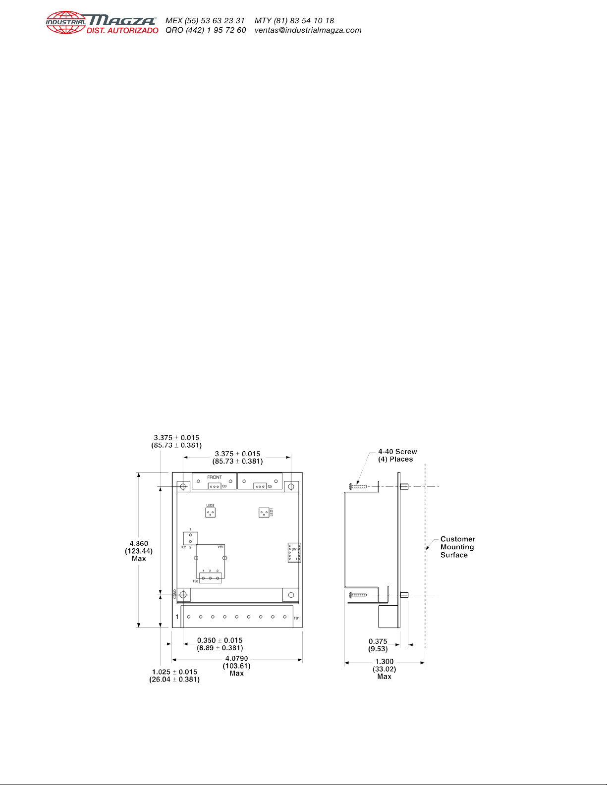
Mounting . . . . . . . . . . . . . . . . . . . . . . . . . . . . . 4
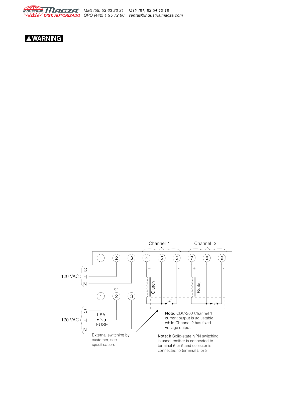
Electrical Connections. . . . . . . . . . . . . . . . . . . 6
Internal Adjustments . . . . . . . . . . . . . . . . . . . 11
Troubleshooting Checklist . . . . . . . . . . . . . . . 12
Warranty . . . . . . . . . . . . . . . . . . . . . . Back Page
or control panel. The standard version is offered
the same as before, but with the chassis version
added. The CBC-200-1 and CBC-200-C1
version is being offered where an external limit
adjustment potentiometer is required. The
CBC-200-2 and CBC-200-C2 version maintains
the limit adjust potentiometer on the PC board
but allows for an external potentiometer for level
adjustment of the output. This allows the output
to be controlled from zero to maximum level on
both the current adjust channel and steady state
output channel. The CBC-200-3 and
CBC-200-C3 allow for both the current limit and
level adjustment potentiometers to be mounted
remotely.
Operations of all units are identical except for
the method of the control potentiometer
mounting. All units that have external poten-
tiometer options have terminal blocks mounted
on the PC boards for connection of the poten-
tiometers.
The potentiometers used can be supplied either
as optional accessory items or be obtained from
a local electronic supply house.
A short circuit protection scheme is integral
which trips on occurrence of line to line shorts
on the output. No protection is provided for line
to ground shorts because the unit is not
isolated.
Two LED indicators are provided on the front
panel of the control for “POWER” and “SHORT”
indications. The green indicator marked
“POWER” is illuminated whenever the AC input
power is applied to the control. A red indicator
marked “SHORT” is illuminated whenever a
short circuit condition occurs in either of the
outputs. To reset, power must be removed, the
shorted condition cleared, and the AC input
power reapplied to the control.
The enclosed version may be used with or
without the cover. Removal of the plastic cover
when the control is used in an enclosure will
increase the operating temperature range of the
control.
The chassis mount version does not have a
cover and must be mounted in an enclosure or
control panel.
Failure to follow these
instructions may result in product dam-
age, equipment damage, and serious or
fatal injury to personnel.
Introduction
Warner Electric’s CBC-200 series Constant
Current Clutch Brake Controls are solid-state
electronic power supplies designed to operate
any of the Warner Electric 90 Volt clutches and
brakes, including fail safe designs. They can
operate a single clutch or brake, two clutches,
two brakes, a combination clutch and brake, or
a combination clutch and fail safe brake,
depending on the switching arrangement used
and the application requirements.
The CBC-200 series controls operate from 120
VAC single-phase input power. They provide
constant current output as set by the torque
adjustment potentiometers on the front panel or
remote potentiometer. Additionally, on some
versions a level adjust can be used to set the
operating level with the torque adjustment
setting the maximum current level. On the
CBC-200 series Channel 2 is a fixed output level
and an adjustable output on Channel 1. Output
current ranges are selectable for the adjustable
output channels in one of five ranges by the DIP
switches located on the control’s printed circuit
board.
Several versions of the CBC-200 are provided to
handle a wide range of applications. These
include both enclosed and chassis mount
versions for mounting in an external enclosure

Specifications
Input Power: 120 VAC, +10%, -15%, 50/60 Hz,
single phase, 215 VA maximum.
Output: Pulse-width modulated full wave rectified
DC. Constant current, switch selectable
ranges, for one channel and fixed 90VDC
second channel, designed for 90 volt DC
clutches and brakes.
Ambient Temperature: -32˚ F to + 113˚F (0˚C to + 45˚)
with plastic cover installed. -32˚F to +150˚F
(0˚C to +66˚C) with plastic cover removed, or
board assembly only.
Circuit Protection: Internal short circuit protection
on outputs, but no circuit protection for AC
ground faults. Optional customer supplied
fusing on AC line, 1.5 amps, 250 VAC
Fast-Acting type fuse recommended.
Control Adjust: CBC-200 and CBC-200-C via front
panel potentiometer for current adjustment.
CBC-200-1 and CBC-200-C1 via external
mounted potentiometer for current adjustment.
CBC-200-2 and CBC-200-C2 current
adjustment via front panel potentiometer and
output level adjust via external potentiometer.
CBC-200-3 and CBC-200-C3 both current
adjust and limit adjustment are via external
potentiometers.
Status Indicators: “POWER” – green LED indicating
AC power is applied to the control.
“SHORT” – red LED indicating that a short
circuit condition exists on one or both of
the outputs.
Internal Adjustments: Current Range Selection via
DIP switch, SW1
Current Ranges:
Switch Setting 1 2 3 4 5
Max Output, ma 60 175 245 305 533
3
Warner Electric • 800-825-9050 P-269
External Switching: Mechanical or electromechanical
Electromechanical
Customer supplied; 1 amp, 125 V minimum
rating.
Solid-state NPN isolated transistor
Customer supplied; 2 amp, 250V minimum rat-
ing. Maximum off state leakage current < 1 ma.
External Pots:
Remote current adjust pot
customer supplied; 10,000 ohm, 2 watt, linear,
maximum distance from control to potentiome-
ter not to exceed 10 feet.
Optional Accessory Pot Kit;
part number, 6011-101-002
Remote Level adjust pot
Customer supplied; 5,000 ohm, 2 watt, linear,
maximum distance from control to potentiome-
ter not to exceed 10 feet.
Optional Accessory Pot Kit;
part number, 6011-101-001.
Wiring Entrance: Two 7/8” diameter entrance holes
located on the bottom of the control chassis on
enclosed units. No conduit entrances are on
chassis mount versions.
Enclosure: Rated NEMA 1 only – Control must be
kept clear of foreign materials, dust, grease and
oil which might affect its operation.
Part Numbers:
Enclosed Versions
CBC-200 6011-448-001
CBC-200-1 6011-448-002
CBC-200-2 6011-448-003
CBC-200-3 6011-448-004
Chassis Versions
CBC-200-C 6011-448-005
CBC-200-C1 6011-448-006
CBC-200-C2 6011-448-007
CBC-200-C3 6011-448-008

4Warner Electric • 800-825-9050 P-269
Mounting
Enclosed Units
Any vertical, horizontal, or angled surface is suit-
able for mounting the CBC-200, CBC-200-1,
CBC-200-2, CBC-200-3 control.
Follow these procedures to mount your control.
❑1. Remove the front cover by removing the
top and bottom retaining screws.
❑2. Set the control on the mounting surface
and mark for the three mounting holes in
accordance with “Dimensions.” (See Figure 1)
❑3. Install the top two mounting bolts or
screws until they are nearly flush, set the
control over the larger top mounting holes
and pull down to position the control.
❑4. Tighten the top bolts or screws and install
the bottom bolt or screw and tighten.
This completes the mounting of the control. The
control is now ready for final wiring. Refer to the
wiring section for final wiring.
If the CBC-200-1, CBC-200-2, or the
CBC-200-3 control is used, the following
additional procedure must be followed.
❑1. For the CBC-200-2 remove the knob from
the control.
❑2. On the CBC-200-1, CBC-200-2 or
CBC-200-3 remove the four screws that hold
the faceplate bracket and PC board to the
chassis plate.
❑3. Bring the external potentiometer wires
through the conduit entrance hole and wire
the potentiometers to the appropriate
terminals blocks as shown in (Figure 5)
CBC-200-2, (Figure 6) CBC-200-1, or
(Figure 7) CBC-200-3.
❑4. After wiring the external potentiometers,
mount the PC board assembly and faceplate
assembly to the chassis with the four screws
previously removed. Replace the knob if the
CBC-200-2 was installed.
This completes the preliminary wiring of the
remote potentiometers. The control is now ready
for final wiring. Refer to the wiring section for
final wiring.
Note: Be careful not to pinch or crimp the pot
wiring to prevent shorting to the housing or
components.
Figure 1

5
Warner Electric • 800-825-9050 P-269
Chassis Mount PC Board Assemblies
Any vertical, horizontal, or angled surface is
suitable for mounting the CBC-200-C,
CBC-200-C1, CBC-200-C2, or CBC-200-C3
control.
Follow these procedures to mount your control:
❑1. Determine the mounting location where the
control will be placed.
❑2. Layout the mounting hole dimensions and
drill holes and taps using a 4-40 tap. (Figure 2)
❑3. If the CBC-200-C1, CBC-200-C2 or
CBC-200-C3 controls are used, wire the
external potentiometers to the appropriate
terminal blocks. (See Figure 2)
❑4. Place the faceplate over the PC board
assembly aligning the holes on the faceplate
with the holes on the PC board.
❑5. Using the 4-40 screws supplied, mount the
PC board and faceplate assembly to the
panel. Insure that the faceplate aligns cor-
rectly and does not contact any of the
components on the PC board.
❑6. Tighten all four mounting screws securely.
❑7. If the CBC-200-C or CBC-200-C2 was
used, insert the knob on the internal poten-
tiometer shaft.
❑8. Attach the switch setting label next to the
control as a reference for switch set up.
Note: Be careful not to pinch or crimp the
potentiometer wiring to prevent shorting to the
chassis or control components.
This completes the mounting of the control. The
unit is now ready for final wiring. Refer to the
wiring section for final wiring.
Figure 2

6Warner Electric • 800-825-9050 P-269
Electrical Connections
All electrical current must be
off when making electrical connections to
prevent injury or death which can result from
contact with live wires.
AC Input Power Connections
❑1. Connect Earth Ground wire to Terminal 1
and tighten securely.
❑2. Connect the Hot side of the 120 VAC line
to Terminal 2 and tighten securely.
Note: Customer supplied fuse is desirable.
See diagram for connection and sizing.
❑3. Connect the neutral side of the 120 VAC
line to Terminal 3 and tighten securely.
❑4. For power applied clutch/brake
arrangement proceed to the wiring
diagram and section below.
Normal Clutch/Brake Wiring
(Power applied clutches or brakes)
Figure 3
❑1. Connect either the clutch or brake magnet to
Terminals 4 and 5. Tighten Terminal 4 securely.
❑2. Connect the other magnet, either brake or
clutch to Terminals 7 and 8. Tighten Terminal 7
securely.
❑3. Connect switching for Channel 1 to Terminals
5 and 6. Tighten both terminals securely.
❑4. Connect switching for Channel 2 to Terminals
8 and 9. Tighten both terminals securely.
❑5. Set DIP Switch, SW1 for proper current
setting before applying power to the control.
See INTERNAL SWITCH SETTINGS CHART for
proper DIP Switch settings
❑6. If external potentiometers are being used,
then proceed to the external potentiometer
wiring section. If they are not used, this
completes the wiring of the control.
❑7. Double check all connections before
applying power.
Clutch/Brake and Switch Wiring

7
Warner Electric • 800-825-9050 P-269
Clutch – Electrically Released Brake Wiring
(Power on clutch/power off brake)
All electrical current must be
off when making electrical connections to
prevent injury or death which can result
from contact with live wires.
AC Input Power Connections
❑1. Connect Earth Ground wire to Terminal 1
and tighten securely.
❑2. Connect the Hot side of the 120 VAC line
to Terminal 2 and tighten securely.
Note: Customer supplied fuse is desirable. See
diagram for connection and sizing.
❑3. Connect the neutral side of the 120 VAC
line to Terminal 3 and tighten securely
❑4. For electrically released brake-clutch
arrangement proceed to the wiring section
below.
❑1. Connect the Brake to Terminals 4 and 5.
Observe the polarity when making connec-
tions. Tighten Terminal 4 securely.
❑2. Connect the Clutch to Terminals 7 and 8.
Tighten Terminal 7 securely.
❑3. Connect the switching for Channel 1 to
Terminals 5 and 6. Tighten terminals securely.
❑4. Connect the switching for Channel 2 to
Terminals 8 and 9. Tighten terminals securely.
❑5. Set DIP Switch, SW1 for proper current
setting before applying power to the control
See INTERNAL SWITCH SETTINGS CHART
for proper DIP Switch settings.
❑6. If external potentiometers are being used,
then proceed to the external potentiometer
wiring section. If external potentiometers are
not used, this completes the wiring of the
control.
❑7. Double check all connections before
applying power.
Clutch/Brake and Switch Wiring
Figure 4

8Warner Electric • 800-825-9050 P-269
External Potentiometer wiring for
CBC-200 Series Controls
Enclosed Models
CBC-200-1
CBC-200-2
CBC-200-3
Depending on which control is being used,
options for external potentiometer are available
via terminal blocks on the PC board of the unit.
❑1. For CBC-200-2 only, remove the internal
torque adjust knob.
❑2. Remove the four screws that hold the
bracket assembly and PC Board to the
chassis. This step applies to all versions of
the enclosed models.
❑3. Based on which model used, route the pot
cable through one of the conduit entrance
holes on the bottom of the unit and wire to
the appropriate terminal block on the PC
board. Refer to the wiring diagrams on this
page for the proper connections.
CBC-200-1
External Current Limit Adjustment
❑1. Wire the external current limit potentiome-
ter to Terminal Block TB-3 for
Channel 1 as shown in the diagram.
(See Figure 6)
❑2. If the accessory pot kit is used, then wire
per the colors as shown in the diagram.
❑3. Make sure all terminals are securely
fastened and the wiring cable is secured so
that it can’t pull out of the terminals.
Figure 6
Figure 5
Figure 7

9
Warner Electric • 800-825-9050 P-269
CBC-200-2
External Level Adjust with Internal
Current Limit Adjust
❑1. Wire the external level adjust potentiome-
ter on Terminal Block TB-2 as shown in the
diagram. (See Figure 5)
❑2. If the accessory pot kit is used, wire
according to the colors as shown in the
diagram.
❑3. Make sure all terminals are securely fas-
tened and the wiring cable is secured so that
it can’t pull out of the terminals.
Note: The level adjustment controls both the
current adjustable output, channel 1 as well as
the steady state output, channel 2.
❑4. After the pot(s) has been wired to the
appropriate terminal block, mount the PCB
and bracket assembly and reattach to the
chassis with the four screws removed in step
2 above.
❑5. For the CBC-200-2 reattach the internal
potentiometer knob.
❑6. Double check all wiring for both the poten-
tiometer and the main terminal block to
insure proper connections.
CBC-200-3
External Current Limit and Level Adjust
❑1. Wire the external current limit adjust
potentiometer to Terminal Block TB-3 for
Channel 1 as shown in the diagram.
(See Figure 7)
❑2. If the accessory pot kit is used, wire per
the color codes as shown.
❑3. Make sure all terminals are securely
fastened and the wiring cable is secured so
that it can’t pull out of the terminals.
❑4. Wire the external level adjust potentiome-
ter to Terminal Block TB-2 as shown in the
diagram. (See Figure 7)
❑5. If the accessory pot kit is used, wire per
the color codes as shown.
❑6. Make sure all terminals are securely
fastened and the wiring cable is secured so
that it can’t pull out of the terminals.
Note: The level adjustment controls both the
current adjustable output, channel 1 as well as
the steady state output, channel 2.

10 Warner Electric • 800-825-9050 P-269
CBC-200-C2
External Level Adjust with Internal
Current Limit Adjust
❑1. Wire the external level adjust potentiome-
ter on Terminal Block TB-2 as shown in the
diagram. (See Figure 5)
❑2. If the accessory pot kit is used, then wire
according to the colors as shown in the
diagram
❑3. Make sure all terminals are securely fas-
tened and the wiring cable is secured so that
it can’t pull out of the terminals.
Note: The level adjustment controls both the
current adjustable output, channel 1 as well as
the steady state output, channel 2.
CBC-200-3
External Current Limit and Level Adjust
❑1. Wire the external current limit adjust
potentiometer to Terminal Block TB-3 for
Channel 1 as shown in the diagram. (See
Figure 7)
❑2. If the accessory pot kit is used, wire per
the color codes as shown.
❑3. Make sure all terminals are securely
fastened and the wiring cable is secured so
that it can’t pull out of the terminals.
❑4. Wire the external level adjust potentiome-
ter to Terminal Block TB-2 as shown in the
diagram. (See Figure 7)
❑5. If the accessory pot kit is used, wire per
the color codes as shown.
❑6. Make sure all terminals are securely
fastened and the wiring cable is secured so
that it can’t pull out.
Note: The level adjustment controls both the
current adjustable output, channel 1 as well as
the steady state output, channel 2.
Chassis Mount Models
CBC-200-C1
CBC-200-C2
CBC-200-C3
❑1. The CBC-200-C series chassis mount
version controls are shipped with the face
plate bracket assembly loose.
❑2. Wire the control per the appropriate Wiring
configuration for the type of external poten-
tiometer being used.
❑3. Based on which model used, route the pot
cable accordingly. Make sure to keep the
cable away from components which may get
hot during operation or points where the
cable may become pinched. Refer to the
wiring diagrams for the proper connection.
❑4. After the pot(s) have been wired to the
appropriate terminal blocks, mount the PCB
and bracket assembly and attach to the
mounting surface with the four screws
provided.
CBC-200-C1 External current limit
adjustment
❑1. Wire the external current limit potentiome-
ter to Terminal Block TB-3 for Channel 1 as
shown in the diagram. (See Figure 6)
❑2. If the accessory pot kit is used, wire per
the colors as shown in the diagram.
❑3. Make sure all terminals are securely
fastened and the wiring cable is secured so
that it can’t pull out of the terminals.

11
Warner Electric • 800-825-9050 P-269
Internal Adjustments
The internal DIP Switch on the control circuit board adjusts the control for the proper current range to
the clutch and/or brake coil being used. The chart below indicates the proper setting based on coil
resistance and Warner Electric product. To adjust for products not listed, obtain coil resistance
information and set switches per coil resistance.
Switch DIP No. 1 2 3 4 5
Coil Resistance 1000-1550 350-999 250-349 205-249 100-204
at 20° C (W)
Current Range 0 - 60 ma 0 - 175 ma 0 - 245 ma 0 - 305 ma 0 - 533 ma
Warner Electric SF-120 EC-375 ATC-25 SF-500 ATC-115
Clutch Models SF-170 EC-475 PC-500 SF-650 SF-1525HT
SF-250 EM-50 SF-825 SF-825BM
SF-400 EM-100 PC-1000 PC-825
EM-180 SF-1225 SF-1000
UM-50 PC-1225 SF-1525
UM-100 PC-1525 EC-650
UM-180 EC-1000 EC-825
UM-50C EM-210 EC-1225
UM-180C UM-210 ATC-55
EUM-50 UM-215
EUM-100 UM-210C
EUM-180 EUM-210
EUM-215
Warner Electric PB-120 EB-375 ATB-25 EB-825 EMFB-210
Brake Models PB-170 EB-475 PB-500 EMFB-180 UMFB-210
PB-250 EM-50 PB-650 UMFB-180 ER/FB-650
PB-400 EM-100 PB-1000 ER/FB-475 ATB-115
EM-180 PB-1225 ATB-55 ER-1225
UM-50 PB-1525 ER-825
UM-100 EB-650
UM-180 EB-1000
UM-50C EB-1225
UM-180C EMFB-50
EUM-50 UMFB-50
EUM-100 ER/FB-375
EUM-180 EM-210
UM-210
UM-215
UM-210C
EUM-210
EUM-215
Note: Only one switch number is to be set to the “on” position at any time.

12 Warner Electric • 800-825-9050 P-269
System Troubleshooting
A. Symptom:
Green LED indicator marked “Power” does not come on when power is applied to the CBC-200 Controller.
Probable Cause Solution
No Power is applied to the Control • Check that AC power is applied to the control.
• Incorrect wiring on AC power to the control.
• Check for 120 VAC at Terminals 2 and 3 with an AC Voltmeter.
Optional line fuse is blown • Check for blown fuse – replace.
Indicator LED is defective • Check for 120 VAC at Terminals 2 and 3 of the control.
• Check for output voltage at output terminals for Channel 1 and
Channel 2. If voltage is not present, replace control or board.
B. Symptom: Red LED marked “short” illuminates
Probable Cause Solution
Shorted magnet coil • Check resistance of magnet coil used and replace if necessary.
Wiring between control and magnet shorting • Check for shorted conditions in wiring between the magnets and
the control, and wiring to chassis ground.
Improper magnet coil voltage • Check magnet for proper coil voltage rating.
Transient noise • Check for source of transient noise and suppress. Wire control
using shielded cables. Segregate wiring runs.
C. Symptom: Magnets do not engage when power is applied.
Probable Cause Solution
External switching improperly wired • Check wiring and switch connections and rewire if necessary.
Torque adjust set to zero (0) • Set torque adjustment potentiometer to maximum level.
Current range switch improperly set • Check DIP Switch settings per chart and reset if required.
No power applied to the control • Refer to Symptom A above.
System incorrectly wired • Check wiring per the wiring diagram and rewire if necessary.
Fail Safe brake used in place • Check to insure that a fail safe brake is not being used in place of
of power applied brake a power applied brake. Replace brake with correct brake.
D. Symptom: Magnets do not disengage when power is removed
Probable Cause Solution
External switches incorrectly wired • Check wiring of switching circuits and rewire if necessary.
Fail Safe brake magnet being used • Check to see if fail safe brake is being used in place of power
applied brake.
Faulty control • Replace control and see if problem is resolved.
E. Symptom: Magnets do not appear to have enough torque
Probable Cause Solution
DIP Switch improperly set • Check DIP switch setting per chart and reset if necessary.
Magnets incorrectly wired • Check wiring between control and magnets and rewire if required.
Torque adjust potentiometer set too low • Check setting of torque adjust potentiometer and set to maximum
if required. Check for correct wiring if external pots are used.
Magnets are incorrectly sized • Verify sizing is correct by repeating selection process.

13
Warner Electric • 800-825-9050 P-269
Notes:

Warranty
Warner Electric LLC warrants that it will repair or replace (whichever it deems advisable) any
product manufactured and sold by it which proves to be defective in material or workmanship
within a period of one (1) year from the date of original purchase for consumer, commercial or
industrial use.
This warranty extends only to the original purchaser and is not transferable or assignable without
Warner Electric LLC’s prior consent.
Warranty service can be obtained in the U.S.A. by returning any defective product, transportation
charges prepaid, to the appropriate Warner Electric LLC factory. Additional warranty information
may be obtained by writing the Customer Satisfaction Department, Warner Electric LLC, 449
Gardner Street, South Beloit, Illinois 61080, or by calling 815-389-3771.
A purchase receipt or other proof of original purchase will be required before warranty service is
rendered. If found defective under the terms of this warranty, repair or replacement will be made,
without charge, together with a refund for transportation costs. If found not to be defective, you
will be notified and, with your consent, the item will be repaired or replaced and returned to you
at your expense.
This warranty covers normal use and does not cover damage or defect which results from
alteration, accident, neglect, or improper installation, operation, or maintenance.
Some states do not allow limitation on how long an implied warranty lasts, so the above limitation
may not apply to you.
Warner Electric LLC’s obligation under this warranty is limited to the repair or replacement of the
defective product and in no event shall Warner Electric LLC be liable for consequential, indirect,
or incidental damages of any kind incurred by reason of the manufacture, sale or use of any
defective product. Warner Electric LLC neither assumes nor authorizes any other person to give
any other warranty or to assume any other obligation or liability on its behalf.
WITH RESPECT TO CONSUMER USE OF THE PRODUCT, ANY IMPLIED WARRANTIES WHICH
THE CONSUMER MAY HAVE ARE LIMITED IN DURATION TO ONE YEAR FROM THE DATE OF
ORIGINAL CONSUMER PURCHASE. WITH RESPECT TO COMMERCIAL AND INDUSTRIAL
USES OF THE PRODUCT, THE FOREGOING WARRANTY IS IN LIEU OF AND EXCLUDES ALL
OTHER WARRANTIES, WHETHER EXPRESSED OR IMPLIED BY OPERATION OF LAW OR
OTHERWISE, INCLUDING, BUT NOT LIMITED TO, ANY IMPLIED WARRANTIES OF
MERCHANTABILITY OR FITNESS.
Some states do not allow the exclusion or limitation of incidental or consequential damages, so
the above limitation or exclusion may not apply to you. This warranty gives you specific legal
rights and you may also have other rights which vary from state to state.
Changes in Dimensions and Specifications
All dimensions and specifications shown in Warner Electric catalogs are subject to change without
notice. Weights do not include weight of boxing for shipment. Certified prints will be furnished
without charge on request to Warner Electric.
Warner Electric LLC
449 Gardner Street • South Beloit, IL 61080
815-389-3771 • Fax: 815-389-2582
www.warnerelectric.com
An Altra Industrial Motion Company
P-269 819-0407 9/07 Printed in USA
This manual suits for next models
9
Table of contents
Other Warner Electric Control Unit manuals
Popular Control Unit manuals by other brands

ABB
ABB FCB400 Series Configuration guide

Emerson
Emerson FISHER RSS Series instruction manual

Task Force Tips
Task Force Tips FlipTip Instruction for operation and maintenance

Danfoss
Danfoss GBC 6s installation guide

Moxa Technologies
Moxa Technologies MiiNePort W1 Series Quick installation guide

Primary fluid systems
Primary fluid systems ECO-110 instruction manual