Warner Electric MCS-805-1 User manual

Installation Instructions
P-239-31
MCS-805 Series Clutch/Brake Controls

2Warner Electric • 800-234-3369 P-239-31
Failure to follow these
instructions may result in product damage,
equipment damage, and serious or fatal
injury to personnel.
Contents
Introduction................................2
Specifications...............................3
Installation.................................4
Dimensions ................................5
Connection.................................5
Warranty...........................backcover
Introduction
Warner Electric’s CS-805-1 and CS-805-2
series clutch/brake controls are designed for
operation with Warner Electric electrically
released brakes. The correct brake release volt-
age is a specific point between 35-75VDC. This
point is set by adjusting the control at the time
of brake installation. These controls are factory
set for 60 volts output.
The CS-805-1 and CS-805-2 controls oper-
ate from 120/230VAC single phase input power.
Switching may be provided on either the AC or
DC side of the control.
The CS-805-1 and the CS-805-2 have an
internal adjustment potentiometer that is use for
the release band adjustment. The CS 805-2 is
similar to the CS-805-1 except that it has
torque adjustment capability for soft stop appli-
cations. The CS 805-2 requires two switching
circuits when used for those applications requir-
ing soft engagement.

3
Warner Electric • 800-234-3369 P-239-31
Specifications:
Input power:
• CS-805-1 120/230VAC ± 10%,
50/60Hz, single phase.
• CS-805-2 120/230VAC ± 10%,
50/60Hz, single phase
Output:
CS-805-1 35-75VDC, 0.40 amps
CS-805-2 35-75VDC, 0.40 amps
Switching inputs:
(external to control, supplied y customer)
• DC switching: single pole, single throw.
inimum contact rating 1 amp, 120 VDC.
• AC switching: single pole, single throw.
inimum contact rating 1 amp, 120 VAC.
Am ient temperatures:
-20° to 150°F (-29° to 65°C)
Circuit protection: (fusing)
3/4 Amps, 250V Slow Blow, 3AG
Adjustments:
Release band adjustment (via internal poten-
tiometer)
CS-805-2 only: Torque adjust (via external
potentiometer)
Wiring Entrance:
Two 7/8" diameter conduit entrance holes
located on the bottom and on the top of the
control chassis.
Reorder Information
Model Part No.
CS-805-1 6090-448-006
CS-805-2 6090-448-007
Mounting
Any vertical, horizontal, or angled surface is suit-
able for mounting the CS-805-1 or CS-805-
2. Follow these procedures to mount your con-
trol:
a. Remove the front cover by removing the top
retaining screws.
b. Set the control on the mounting surface and
mark for the four mounting holes in accor-
dance with dimensions.
c. Install and tighten the four screws.
The control is now ready to be wired.
To avoid injury (or even death),
always make certain all power is off efore
attempting to install this control or any elec-
trical equipment. Do not touch the oard if
power is applied.

4Warner Electric • 800-234-3369 P-239-31
Installation
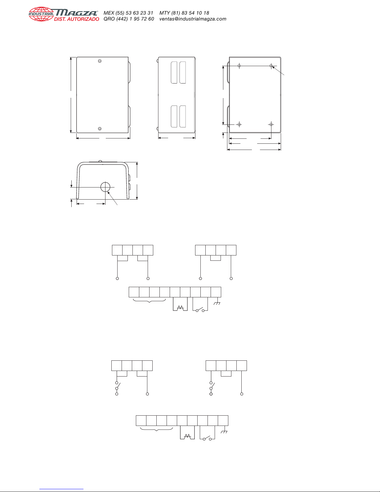
a. For 115VAC: Connect power supply to termi-
nals 1 and 4. Install a jumper between termi-
nal 1 and terminal 2. Also, install a second
jumper between terminal 3 and terminal 4.
For 230VAC: Connect power supply to termi-
nals 1 and 4. Install a jumper between termi-
nal 2 and terminal 3.
b. A chassis ground should be provided as a
non-current conducting ground wire (color
coded green). Connect this ground to termi-
nal 9.
c. Switching.
• For switching DC side: switch must be
connected to terminals 7 and 8. Switch
open will allow brake to be engaged.
Switch closed will release the brake. For
CS-805-2 Only: Switch open will allow
brake to be partially engaged and AC
power off will allow brake to be fully
engaged.
• For switching AC side: Line power off will
allow brake to be engaged. Line power on
will release brake. Install a jumper
between terminals 7 and 8.
d. Connect the positive terminal of the brake to
terminal 6 on the control and the negative
terminal of the brake to the terminal 5 on the
control.
Brake Release Adjustment
When setting the CS-805 control, the objec-
tive is to achieve armature release by adjusting
the coil voltage so it counteracts the permanent
magnet to the maximum extent possible.
Proceed as follows:
a. Turn on the control. Loosen locking nut on
the adjustment potentiometer. Turn the
potentiometer adjusting screw to the maxi-
mum counterclockwise position. Slowly turn
the adjustment screw clockwise until the
brake armature disengages from the magnet.
If the usual autogap spring is used, this will
normally cause the armature to separate
approximately 1/32" from the magnet. If the
autogap is not used, an external release force
of approximately 5-10 pounds should be
applied by hand, to detect the point of arma-
ture release. Using a voltmeter, note and
record the voltage at this point.
b. Turn the adjusting screw to the maximum
clockwise position that will normally cause
the armature to be reengaged. If the armature
does not make contact, it should be physi-
cally moved into contact, with caution exer-
cised to prevent fingers from being injured.
c. Turn the adjusting screw slowly counterclock-
wise until the armature releases through the
same technique as used under (a). Note and
record the voltage, which will be somewhat
higher than the value noted under (a). Adjust
the final voltage setting to the mid-point
between the two readings and tighten the
locking nut on the adjustment screw. The
brake is then ready for normal operation.
For CS-805-2 Only: Set partial engagement
torque the external potentiometer. Switch con-
nected to terminals 7 and 8 must be open to
make this adjustment. A setting of 10 gives
maximum torque.

5
Warner Electric • 800-234-3369 P-239-31
Dimensions
Top and Bottom
3-7/16"
1-1/8"
2-5/8"
7/8" Diameter Knockouts for
1/2" Conduit Both Ends
Typical
Back
3-3/4"
6"
4-13/16"
5"
9/16"
9/32" Diameter
4 Mounting Holes
Clearance for 1/4" Screw
Side
3-7/16"
Front
5"
7-1/8"
Connection
123456789
AC INPUT
120/230 VAC
50/60 Hz Brake
-+
S1GND
DC Switching
(Jumper if not used)
1234
120 VAC
1234
230 VAC
123456789
AC INPUT
120/230 VAC
50/60 Hz Brake
-+
S1GND
DC Switching
Closed - brake released
Open - brake in tq. adj. mode
1234 1234
120 VAC 230 VAC
S1S1
S1Open - brake engaged
S2Closed - brake released
or tq. adj. mode per S1

Warner Electric, Inc.
449 Gardner Street
¥South Beloit, IL 61080
815-389-3771 ¥Fax: 815-389-2582
www.warnerelectric.com
P-239-31 10/02 Printed in USA
Warranty
Warner Electric, Inc. warrants that it will repair or replace (whichever it deems advisable) any product
manufactured and sold by it which proves to be defective in material or workmanship within a period
of one (1) year from the date of original purchase for consumer, commercial or industrial use.
This warranty extends only to the original purchaser and is not transferable or assignable without
Warner Electric, Inc.’s prior consent.
Warranty service can be obtained in the U.S.A. by returning any defective product, transportation
charges prepaid, to the appropriate Warner Electric, Inc. factory. Additional warranty information may
be obtained by writing the Customer Satisfaction Department, Warner Electric, Inc., 449 Gardner
Street, South Beloit, Illinois 61080, or by calling 815-389-3771.
A purchase receipt or other proof of original purchase will be required before warranty service is rendered.
If found defective under the terms of this warranty, repair or replacement will be made, without charge,
together with a refund for transportation costs. If found not to be defective, you will be notified and,
with your consent, the item will be repaired or replaced and returned to you at your expense.
This warranty covers normal use and does not cover damage or defect which results from alteration,
accident, neglect, or improper installation, operation, or maintenance.
Some states do not allow limitation on how long an implied warranty lasts, so the above limitation may
not apply to you.
Warner Electric, Inc.’s obligation under this warranty is limited to the repair or replacement of the
defective product and in no event shall Warner Electric, Inc. be liable for consequential, indirect, or
incidental damages of any kind incurred by reason of the manufacture, sale or use of any defective
product. Warner Electric, Inc. neither assumes nor authorizes any other person to give any other
warranty or to assume any other obligation or liability on its behalf.
WITH RESPECT TO CONSU ER USE OF THE PRODUCT, ANY I PLIED WARRANTIES WHICH THE
CONSU ER AY HAVE ARE LI ITED IN DURATION TO ONE YEAR FRO THE DATE OF ORIGINAL
CONSU ER PURCHASE. WITH RESPECT TO CO ERCIAL AND INDUSTRIAL USES OF THE
PRODUCT, THE FOREGOING WARRANTY IS IN LIEU OF AND EXCLUDES ALL OTHER WARRANTIES,
WHETHER EXPRESS OR I PLIED BY OPERATION OF LAW OR OTHERWISE, INCLUDING, BUT NOT
LI ITED TO, ANY I PLIED WARRANTIES OF ERCHANTABILITY OR FITNESS.
Some states do not allow the exclusion or limitation of incidental or consequential damages, so the
above limitation or exclusion may not apply to you. This warranty gives you specific legal rights and
you may also have other rights which vary from state to state.
Changes in Dimensions and Specifications
All dimensions and specifications shown in Warner Electric catalogs are subject to change without
notice. Weights do not include weight of boxing for shipment. Certified prints will be furnished without
charge on request to Warner Electric.
This manual suits for next models
1
Table of contents
Other Warner Electric Power Supply manuals
Popular Power Supply manuals by other brands

Altronix
Altronix OLS20220 quick guide

HP
HP 1122A Operating note

Elmdene
Elmdene G1380 BMU-y Series instruction sheet

POWER ON BOARD
POWER ON BOARD VEC012POB Owner's manual and warranty information

G&D
G&D VisionXS-IP-F-DP-UHR Additional Instructions for Installation and Operation

Advanced Energy
Advanced Energy iLS600 Series user manual