WatchDog WatchDog 3349SS User manual

Sprayer Station
PRODUCT MANUAL
Item # 3349SS
®

2
Contents
Introduction 3
Components 3
Installing the Station 4
Installing SpecWare Mobile Software 13
Configuring the WatchDog Weather Station 14
Using the WatchDog Weather Station 20
Logging Weather and GPS Data 25
Log File Format 27
Troubleshooting 28
How the Sprayer Station Works 31
Specifications 35
Copyright 2008 Spectrum Technologies, Inc.
Updated Feb 19, 2008 for 2nd Generation Connector Box

3
Introduction
Thank you for purchasing the WatchDog Sprayer Station.
The Sprayer Station is designed to provide an accurate
indication and record of the environmental conditions
around a vehicle, whether it is stationary or in motion. It
allows for real-time measurement of weather data before,
during, and after a field operation.
Components
Your WatchDog Sprayer Station package should contain
the following components:
• Sensor Unit
• Mounting Post
• Cable Assembly
• Vehicle Power Adapter
• Hook & Loop Fastener Strips (2)
• SpecWare Mobile CD
• User Guide

4
Installing
the Station
Caution: The blue metal plate and the blue film found in
the wind channel of the Sensor Unit are essential to its
operation. Be careful not to scratch the plate, puncture
the film, or damage them in any way.
Choosing the Mounting Location
The Sensor Unit must be mounted in “clear air”—away
from obstructions in any direction that will interfere with
air flowing through the unit. Ideally, this would be on the
roof of the cab or the tank. If the Sensor Unit is not the
highest point, be sure to mount it far enough from any ob-
struction so there is no interference with the air flow.

5
Because the Sensor Unit has an electronic compass, it
should be at least 3' (1 m) away from strong magnetic
fields from equipment such as radio transmitters. Since it
has a GPS, be sure it is as far as possible from high-
powered transmitting antennas to avoid mutual interfer-
ence. Similarly, mount the Sensor Unit far enough from
an existing GPS unit to avoid interference, and to keep the
Sensor Unit from blocking the GPS unit’s view of the sky.
The Sensor Unit must be installed vertically—NOT tilted
to one side. Tilting the unit will introduce an error in the
compass reading.
If you are using the magnetic mount, remember that you
must have a steel surface to attract the magnet. With a
fiberglass roof, this usually requires applying an adhesive
steel plate, as is used to provide a mounting point for GPS
units. The magnetic mount can also be removed, and a
standard ¼” bolt can be used to attach the mounting post
to the vehicle.
Once you have decided on a location, note which direction
you want the cable to travel. At this time, you may wish
to mark the front of the mounting post (the side which will
be pointing toward the front of the vehicle).

6
Assembling the Sensor Unit, Cable, and Mount
1. Gather the Sensor Unit, Mounting Post, and Cable Assem-
bly.
2. With the nut assembly on the cable near the Sensor Unit
connector, slide the cable into the cable exit slot at the top
of the Mounting Tube. Leave several inches of cable
topped by the connector above the nut assembly.
3. Screw the nut assembly onto the top of the Mounting Tube.
Hand-tighten only. Do not over-tighten. Caution: If you
want to use a thread lock, use plumber’s tape. Do not use a
liquid thread lock as it may weaken the plastic, causing it to
swell and crack.
4. Remove the protective cover from the connector, and the
warning label from the bottom of the Sensor Unit. Plug the
7-pin connector into the Sensor Unit. The alignment key on
the connector fits into a notch in the base of the Sensor
Unit.
5. Be sure the alignment tabs on the Sensor Unit are facing
forward and parallel to the centerline of the vehicle. Re-
member to orient the front of the Mounting Post forward as
well, so the cable will exit in the correct direction. Slide
the captive nut upward and screw it onto the base of the
Sensor Unit. Hand-tighten only. Do not over-tighten. Be

7
careful NOT to rotate the Sensor Unit or loosen the nut as-
sembly from the antenna mount/extension tube. Double
check to be sure the alignment tabs are still facing forward.
Alignment
Please note that for clarity the above diagram shows the sensor
alignment tabs and the cable exit both facing forward, it is un-
common for the cable to run forward from the sensor. It would
usually run to the rear or one of the sides, and the cable exit
should be aligned accordingly. The sensor itself must face for-
Temporary Mount
For temporary mounting of the Sprayer Station, slip the cable
through an open door or window. Caution: do not damage the
cable when closing the door or window. For doors, avoid the
area near the hinges as well as near the latch. Both areas exert
extremely high forces on the cable.

8
Permanent Mount
The Cable Assembly will have to be disassembled in order to
thread the cable through a hole in the wall or roof of the cab.
Although the cable will fit through a ¼” hole, a larger hole is
recommended to fit a grommet, to help ensure a watertight seal.
To disassemble the Cable Assembly:
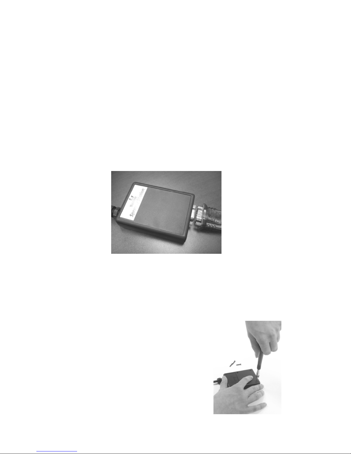
There are two versions of the connector box on the end of the
cable. The first generation box is approximately the size and
shape of a deck of cards, and has a sliding “battery cover”. The
second generation box is smaller, and is labeled as “Item
#3349CB”.
1. Open the connector box, either by sliding the “battery
cover” to remove it (first generation),
or by inserting a screwdriver in the
slots on the side and twisting to sepa-
rate the top and bottom halves (second
generation).
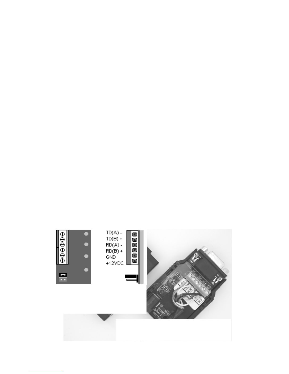
2. Using a small screwdriver (2 mm, 2.5
mm, or 1/10” blade – a small
“electronics” screwdriver has a 1/8”
blade which will not fit), loosen the
six screws, and remove the wires from
the terminal block.
3. Loosen the outer nut on the strain relief (first generation) or
cut the wire tie holding the cable (second generation), and
pull the cable out of the connector box.

9
First Generation Connector
Box - Terminal Block
top view end view
Second Generation Connector Box -
Interior View (with Terminal Block)
To reassemble the Cable Assembly:
1. For a first generation box, thread the cable end through the
strain relief (it can help to remove the outer strain relief nut
completely, slipping it over the cable, and reattaching it
after the cable has been threaded through the strain relief).
2. Thread the six wires into the holes on the side of the termi-
nal block, and tighten the screws to secure the wires. The
wire colors should be matched to the marked terminals as:
• TD(A) or TDA Yellow
• TD(B) or TDB Orange
• RD(A) or RDA White
• RD(B) or RDB Blue
• GND Black
• +12VDC or +12 Red
3. Hand-Tighten the outer strain relief nut (first generation),
or secure the cable with a wire tie through the two holes on
the circuit board (second generation).
4. Slide the “battery cover” back onto the connector box (first
generation), or press the two case halves together, making
sure the LEDs are under the holes next to the label (second
generation).

10
Connecting to your PDA or Laptop
Connect your PDA cable to the 9 pin serial connector on the
connector box. If you are using a laptop or other PC, the power
cable will prevent a direct connection. You must use either a 9
pin M-F serial extension cable, or if your laptop does not have a
serial port, a USB to Serial converter cable (available from
Spectrum Technologies as Item # 3661USB).
If your cable has anchor screws, use them to hold the cable se-
curely to the connector box. However, Murphy’s Law states
that it is more likely that your cable will have anchor nuts, as in
the photo below.
If you encounter this situation, perform the following steps to
connect your cable securely.
For a second generation connector box, use a wrench or pliers
to unscrew the anchor nuts. No disassembly is required.
For a first generation connector box:
1. With a Phillips screwdriver, remove
the four screws from the back of the
connector box.
2. Remove the back of the connector box.
3. Using a screwdriver and a pair of pli-
ers, remove the two nuts from the
screws holding the 9 pin serial connec-
tor .

11
4. Attach your cable to the 9 pin serial connector, and tighten
the two screws to securely hold your cable.
5. Replace the back of the connector box, and secure it with
the four screws removed earlier.

12
In the Cab
Attach the Vehicle Power Cable to the connector box.
Determine a location for the PDA that will provide the
best visibility and access. Next decide where the connec-
tor box will be mounted, based on the length of the PDA
cable, and the distance to the nearest power outlet. Use
the provided Hook & Loop Fastener Strips to secure the
connector box and the PDA. Coil and secure any excess
cable.

13
Insert the SpecWare Mobile installation CD in your com-
puter’s disk drive. On most machines, the software instal-
lation will begin automatically. If it does not, run the
Setup.exe program on the CD. Follow the screen instruc-
tions to complete the installation. A desktop icon and a
Start menu entry will be created to run the PC version of
SpecWare Mobile.
Two additional menu items will be created. These will
prepare to install the the Pocket PC / Windows Mobile
2003 and the Windows Mobile 5 versions of SpecWare
Mobile for the PDA. Run whichever is appropriate for
your PDA (running the wrong install will not harm your
PDA; Windows will hold the install in anticipation of
your connecting a PDA running the other version). The
actual installation is done by ActiveSync. For those who
wish to customize the installation process, “cab” files are
placed in the SpecWare installation directory (this defaults
to “c:\SpecWare”, but can be overridden during the instal-
lation).
Once the SpecWare Mobile software is installed, you are
ready to begin using your Sprayer Station.
The current version of SpecWare Mobile software is
available on the Spectrum Technologies web site at
www.specmeters.com.
Installing
SpecWare Mobile
Software

14
Connect your PDA or PC/laptop to the Sprayer Station
using the cable you attached to the Connector Box earlier.
Ensure that the Sprayer Station is receiving power (there
is a pilot light on the side of the Vehicle Power Cable; the
light should be lit).
Start SpecWare Mobile using the menu or icon. There are
minor differences between the PDA and PC versions of
SpecWare Mobile. These will be pointed out as appropri-
ate in the following instructions. All images are from the
PDA version.
The first time you run SpecWare Mobile, the following
screen will be displayed.
Configuring the
WatchDog
Sprayer Station

15
The first step you must take is tell the PDA or PC where
to find the Sprayer Station. This is done by identifying
the communications (or “serial”) port the Station is
plugged into. For most PDAs, the serial port will be
“COM1”. For PDAs such as the iPaq, which do not have
a built-in serial port, a card can be added to provide a se-
rial port. Documentation provided with these cards will
identify their port number.
If you are uncertain of the COM port on your PC, follow
the steps below.
1. If you are using a USB to Serial converter, plug it into
your PC.
2. From the Start menu, or on the Desktop, right-click
“My Computer”.
3. Select “Properties”.
4. Select the “Hardware” tab.
5. Select “Device Manager”.
6. Click on the “+” to the left of “Ports (COM & LPT)”.
A built-in serial port will be labeled “Communications
Port”. A USB converter will generally have “USB to Se-
rial” in its name. In either case, the communications port
will be in parentheses, as in “(COM1)”.
Once you have identified the communications port you are
using, you must configure the station parameters in
SpecWare Mobile. Using your stylus, tap “Menu” in the
lower left corner. On a PC, click “Menu” in the upper left
corner. Your menu options are displayed on the next
page.

16
Tap (or click) on “Configure Station”. The following

17
On a PDA, a pull-down box will list the available commu-
nications ports. Select the one you are using. On a PC,
there is a text box to type in the number (without the
“COM”).
Next select the measurement system you wish to use.
English selects mph, degrees Fahrenheit, and in-Hg. Met-
ric selects km/h or m/s, degrees Celsius, and hPa/mbar.
The Wind Alarm is set using the up/down arrows. “0”
indicates no alarm. For any other value, if the true wind
reaches or exceeds the Wind Alarm value, the wind speed
value on the main screen will have a bright yellow back-
ground (sound alarms are seldom loud enough on PDAs to
be heard over machinery).
Your Sprayer Station has been preset to send six specific
data messages to the PDA or PC. Under rare situations,
the Sprayer Station can “forget” those settings. The
“Reset Station” button is used to re-educate the Sprayer
Station.
Note: The communications ports on some PDAs were de-
signed to omit key synchronization wires. The Sprayer
Station is so busy sending out weather data that it cannot
notice a message from the PDA or PC without those
wires. In this case, a PC would have to be used to reset
the Sprayer Station.
Tap “OK” to save your selections, and return to the main
screen.
Tap “Menu” again, and then tap “Configure Logging” to
set your data logging preferences.

18
Snapshots and data logs
can be stored in one of
three locations on a
PDA (these options are
omitted from the PC
version, as “My Docu-
ments” is the only
available option).
Choosing “My Documents” places the files in the same-
named folder in the main memory of the PDA. In Micro-
soft ActiveSync, checking “Files” on the “Tools / Op-
tions” screen will cause ActiveSync to copy all files to a
similarly named folder in “My Documents” on your PC.
Choosing “SD Card” places the files on an Secure Digital
memory card inserted into your PDA. The SD card can be
removed and placed in a flash card reader on your PC.
Windows Explorer can be used to move the files onto
your PC.
Similarly, choosing “CF Card” places the files on an
Compact Flash memory card inserted into your PDA. The
CF card can be removed and placed in a flash card reader
on your PC. Windows Explorer can be used to move the
files onto your PC.
Some PDAs have slots for both types of flash memory

19
cards, others support one type or the other. You can
change the location at any point in the future, but existing
files will not be automatically moved from the old to the
new location.
The WatchDog Sprayer Station can log location and
weather data continuously, at a specified interval. Log-
ging is started and stopped via the “Log” button on the
main screen. If you want to disable logging, choose “No
Logging”. Otherwise select a data recording interval.
By default, all log records are written to a single file
named “Sprayer.Log.txt”. This is indicated by the “One
Log File” option.
“New Log File Each Day” places all log records in files
by day, named “Sprayer.Log.yyyymmdd.txt”.
“New File Each Log” creates a new file each time logging
is started using the “Log” button. The files are named
“Sprayer.Log.yyyymmdd.hhmm.txt”.
Checking “New Snapshot File Each Day” saves snapshots
in files named “Sprayer.Snap.yyyymmdd.txt” instead of
the default “Sprayer.Snap.txt”.
The “Log raw data” check box in the lower left corner will
activate logging of the actual weather data messages being
sent from the Sprayer Station. Most people will not want
to activate this option. It can fill all available memory in a
PDA in a short amount of time. It is provided for re-
searchers who require the raw data, and for problem reso-
lution.
Tap “OK” to save your selections, and return to the main
screen.

20
Start SpecWare Mobile using the menu or icon. The “No
data” screen, below, will display until the program re-
ceives weather data from the Sprayer Station Sensor Unit.
If this does not occur within 10 seconds, please refer to
the “Troubleshooting” section of this manual.
Using the WatchDog
Sprayer Station
Once enough data has been received, the display will
switch to the standard display view, as shown on Page 22.
Table of contents
Popular Irrigation System manuals by other brands

Globe
Globe GL4247 DESCRIPTION AND OPERATION

Reliable
Reliable DDX PrePaK Instructions for installation, operation care and maintenance

Cadman
Cadman 6003 OPERATOR'S PARTS and MAINTENANCE MANUAL

K-Rain
K-Rain RPS Select Setting instructions

IR-Tec
IR-Tec G/F8 Instruction manual for use and maintenance

sunjoe
sunjoe Aquajoe AJ-IS10WB instructions