Installation
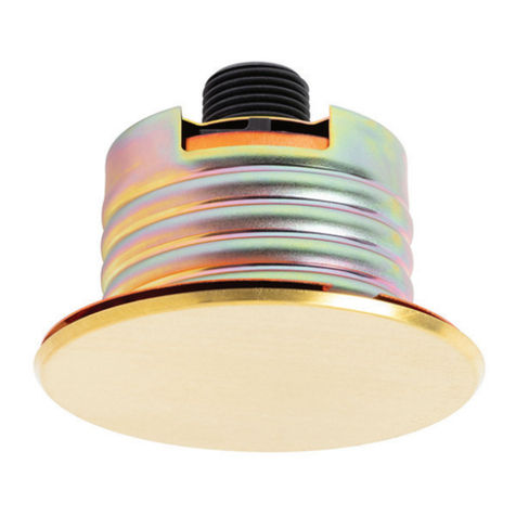
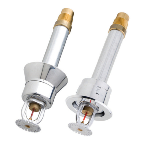
The Series LFII (TY2596) must be
installed in accordance with the
following instructions:
NOTICE
Damage to the fusible Link Assembly
during installation can be avoided by
handling the sprinkler by the support
cup only (i.e., do not apply pressure to
the fusible link Assembly).
A 1/2 inch NPT sprinkler joint should
be obtained with a minimum to max-
imum torque of 7 to 14 ft.lbs. (9,5 to
19,0 Nm). Higher levels of torque may
distort the sprinkler inlet with conse-
quent leakage or impairment of the
sprinkler.
Do not attempt to compensate for in-
sufficient adjustment in the Cover
Plate/Retainer Assembly by under-or
over-tightening the Sprinkler. Read-
just the position of the sprinkler fitting
to suit.
Step 1. The sprinkler must only be
installed in the pendent position and
with the centerline of the sprinkler
perpendicular to the mounting
surface.
Step 2. Remove the Protective Cap.
Step 3. With pipe thread sealant
applied to the pipe threads, and using
the W-Type 18 Wrench shown in Figure
2, install and tighten the Sprinkler/
Support Cup Assembly into the fitting.
The W-Type 18 Wrench will accept a
1/2 inch ratchet drive.
Step 4. Replace the Protective Cap
by pushing it upwards until it bottoms
out against the Support Cup. The
Protective Cap helps prevent damage
to the Deflector and Guide Pins during
ceiling installation and/or during
application of the finish coating of the
ceiling. It may also be used to locate
the center of the clearance hole by
gently pushing the ceiling material
against the center point of the Cap.
NOTICE
As long as the protective Cap remains
in place, the system is considered to
be “Out Of Service”.
Step 5. After the ceiling has been
completed with the 2-1/2 inch (63 mm)
diameter clearance hole and in prep-
aration for installing the Cover Plate
Assembly, remove and discard the
Protective Cap, and verify that the De-
flector moves up and down freely.
If the Sprinkler has been damaged and
the Deflector does not move up and
down freely, replace the entire Sprin-
kler assembly. Do not attempt to mod-
ify or repair a damaged sprinkler.
Step 6. Screw on the Cover Plate As-
sembly until its flange comes in con-
tact with the ceiling.
Do not continue to screw on the Cover
Plate Assembly such that it lifts a ceil-
ing panel out of its normal position.
If the Cover Plate Assembly cannot
be engaged with the Mounting Cup
or the Cover Plate Assembly cannot
be engaged sufficiently to contact the
ceiling, the Sprinkler Fitting must be
repositioned.
Care and
Maintenance
The TycoTyco®Rapid Response™ Series
LFII (TY2596) must be maintained
and serviced in accordance with the
following instructions:
NOTICE
Absence of a Cover Plate may delay the
sprinkler operation in a fire situation.
When properly installed, there is a
nominal 1/8 inch (3,2 mm) air gap be-
tween the lip of the Cover Plate and
the ceiling, as shown in Figure 3. This
air gap is necessary for proper oper-
ation of the sprinkler by allowing heat
flow from a fire to pass below and
above the Cover Plate to help assure
appropriate release of the Cover Plate
in a fire situation. If the ceiling is to be
repainted after the installation of the
Sprinkler, care must be exercised to
ensure that the new paint does NOT
seal off any of the air gap.
Factory painted Cover Plates MUST
NOT be repainted. They should be re-
placed, if necessary, by factory paint-
ed units. Non-factory applied paint
may adversely delay or prevent sprin-
kler operation in the event of a fire.
Do not pull the Cover Plate relative to
the Enclosure. Separation may result.
Before closing a fire protection system
main control valve for maintenance
work on the fire protection system
which it controls, permission to shut
down the affected fire protection sys-
tem must be obtained from the prop-
er authorities and all personnel who
may be affected by this action must be
notified.
Sprinklers which are found to be leak-
ing or exhibiting visible signs of corro-
sion must be replaced.
Automatic sprinklers must never be
painted, plated, coated, or otherwise
altered after leaving the factory. Modi-
fied or over heated sprinklers must be
replaced.
Care must be exercised to avoid dam-
age -before, during, and after installa-
tion. Sprinklers damaged by dropping,
striking, wrench twist/slippage, or the
like, must be replaced.
The owner is responsible for the in-
spection, testing, and maintenance of
their fire protection system and devic-
es in compliance with this document,
as well as with the applicable stan-
dards of the National Fire Protection
Association (e.g., NFPA 25), in addition
to the standards of any other authori-
ties having jurisdiction. The installing
contractor or sprinkler manufacturer
should be contacted relative to any
questions.
NOTICE
The owner must assure that the sprin-
klers are not used for hanging of any
objects and that the sprinklers are only
cleaned by means of gently dusting
with a feather duster; otherwise, non-
operation in the event of a fire or inad-
vertent operation may result.
Automatic sprinkler systems should be
inspected, tested, and maintained by a
qualified Inspection Service in accor-
dance with local requirements and/or
national codes.
Page 4 of 6 TFP440
