Water Care Ion ProSeries Service manual

Installation Instructions & Owner’s Manual
Ion Pro®and CareClear Pro®Series
Water Filters
For Models:
• IPHS
• IPFE
• IPG
• IPCG-AN
• CCP
• CCP-AN

Pre-Installation Instructions for Dealers ........................................ 3
Bypass Valve .............................................................. 4
Installation ................................................................ 5
Programming Procedures.................................................... 8
Start-up Instructions....................................................... 10
Operating Displays and Maintenance ......................................... 11
Replacement Mineral Instructions for CCP Acid Neutralizers ..................... 13
Troubleshooting Guide..................................................... 15
Replacement Parts ........................................................ 20
Installation Fitting Assemblies .............................................. 26
Specifications............................................................. 27
Warranty................................................................. 29
Quick Reference Guide ..................................................... 30
TABLE OF CONTENTS
YOUR WATER TEST
Hardness ______________________ gpg
Iron __________________________ ppm
pH ___________________________ number
*Nitrates ______________________ ppm
Manganese ____________________ ppm
Sulphur _______________________ yes/no
Total Dissolved Solids ____________
*Over 10 ppm may be harmful for human consumption.
Water conditioners do not remove nitrates or coliform bacteria,
this requires specialized equipment.
Look for our
WaterCare
instructional
videos on
PRODUCT INFORMATION
Installing Dealer must ll out this information prior to unit installation
MODEL NUMBER
SERIAL NUMBER
DEALER INFORMATION:
Your WaterCare water filter is a precision built, high quality product. These units will deliver filtered water for many years to
come when installed and operated properly. Please study this manual carefully and understand the cautions and notes before
installing. This manual should be kept for future reference. If you have any questions regarding your water filter, contact your
local dealer.

3
PRE-INSTALLATION INSTRUCTIONS
THE DEALER SHOULD...
•Read this page and guide the installer
regarding day override and time of
regeneration settings prior to installation.
THE INSTALLER SHOULD...
•Program installer settings including day
override, time of regeneration, service alarm,
and alarm buzzer.
•Read Operating Displays and Maintenance
section.
•Set the time of day.
•Read Power Loss and Error Display section.
•Ensure that system and installation are in
compliance with all state and local laws and
regulations.
THE HOMEOWNER SHOULD...
•Read Programming Procedures section.
•Read Operating Displays and Maintenance
section.
The manufacturer has preset the water treatment unit’s sequence of regeneration cycles and cycle times.
GENERAL OPERATING DISPLAYS & NAVIGATION
During normal operation, the default user displays are “time of day” and “gallons per minute”. Flow rate, capacity remaining, days to a regeneration,
and vacation mode are optional displays. For more explanation, consult the “operating displays and maintenance section”. Pressing the NEXT button
on a general operating screen will cycle through the available operating displays.
In any screen other than a general operating display, the NEXT button will proceed to the next step, the REGEN button will return to a previous step,
and the CLOCK button will return to the general operating displays. Any changes made prior to the exit will be incorporated. If no buttons are pressed
within five minutes, the display will return to the general operating displays.
DOUBLE REGENERATION
Two generations within 24 hours are possible with a return to the preset program. To initiate a double regeneration:
1. Press the REGEN button once. “REGEN TODAY” will flash on the display.
2. Press and hold the REGEN button for three seconds until a regeneration begins.
Once the valve has completed the immediate regeneration, the valve will regenerate once more during the preset time.

4
“TREATED”
WATER EXITS
SUPPLY
WATER ENTERS
NORMAL OPERATION
POSITION BYPASS POSITION DIAGNOSTIC POSITION SHUT OFF POSITION
FIGURE 1
SUPPLY
WATER EXITS
SUPPLY
WATER ENTERS
FIGURE 3
SUPPLY
WATER EXITS
SUPPLY
WATER ENTERS
FIGURE 2
NO
WATER EXITS
SUPPLY WATER IS
SHUT OFF
TO THE HOUSE
AND THE VA LV E
FIGURE 4
BYPASS VALVE
The bypass valve is typically used to isolate the control valve from the plumbing system’s water pressure in order to perform control
valve repairs or maintenance. The 1” full flow bypass valve incorporates four positions, including a diagnostic position that allows a
service technician to have pressure to test a system while providing untreated bypass water to the building. Be sure to install bypass
valve onto main control valve before beginning plumbing or make provisions in the plumbing system for a bypass. The bypass body and
rotors are glass-filled Noryl® and the nuts and caps are glass-filled polypropylene. All seals are self-lubricating EPDM to help prevent
valve seizing after long periods of non-use. Internal “O” Rings can easily be replaced if service is required.
The bypass consists of two interchangeable plug valves that are operated independently by red arrow shaped handles. The handles
identify the direction of flow. The plug valves enable the bypass valve to operate in four positions.
1. NORMAL OPERATION POSITION: The inlet and outlet handles point in the direction of flow indicated by the engraved
arrows on the control valve. Water flows through the control valve for normal operation of a water softener or filter. During the
regeneration cycle this position provides regeneration water to the unit, while also providing untreated water to the distribution
system (Fig. 1).
2. BYPASS POSITION: The inlet and outlet handles point to the center of the bypass. The system is isolated from the water
pressure in the plumbing system. Untreated water is supplied to the building (Fig. 2).
3. DIAGNOSTIC POSITION: The inlet handle points toward the control valve and the outlet handle points to the center of bypass
valve. Untreated supply water is allowed to flow to the system and to the building, while not allowing water to exit from the system
to the building (Fig. 3). This allows the service technician to test the unit and perform other functions without disrupting the water
going to the building.
NOTE:The system must be rinsed before returning the bypass valve to the normal position.
4. SHUT OFF POSITION: The inlet handle points to the center of the bypass valve and the outlet handle points away from the
control valve. The water is shut off to the building. The water treatment system will depressurize upon opening a tap in the building.
A negative pressure in the building combined with the unit being in regeneration could cause a siphoning to the building. If water
is available on the outlet side of the unit, it is an indication of water bypassing the system (Fig. 4) (i.e. a plumbing cross-connection
somewhere in the building).

5
GENERAL INSTALLATION & SERVICE WARNINGS
The control valve, fittings and/or bypass are designed to accommodate minor plumbing misalignments. There is a small amount of “give” to properly
connect the piping, but the water treatment unit is not designed to support the weight of the plumbing.
Do not use Vaseline, oils, other hydrocarbon lubricants, or spray silicone anywhere. A silicone lubricant may be used on black “O” Rings, but is not
necessary. Avoid any type of lubricants, including silicone, on red or clear lip seals.
Do not use pipe dope or other sealants on threads. Teflon® tape must be used on the threads of the 1” NPT inlet and outlet and on the threads for
the drain line connection. Teflon® tape is not used on the nut connections or caps because “O” Ring seals are used. The nuts and caps are designed
to be unscrewed or tightened by hand or with the special plastic Service Wrench, #100249864 (CV3193-02). If necessary, pliers can be used to
unscrew the nut or cap. Do not use a pipe wrench to tighten nuts or caps. Do not place screwdriver in slots on caps and/or tap with a hammer.
SITE REQUIREMENTS
• Water pressure – 25-100 psi • Current draw is 0.5 amperes
• Water temperature – 33-100°F (0.5-37.7°C) • The plug-in transformer is for dry locations only
• Electrical – 115/120V, 60Hz uninterrupted outlet
INSTALLATION
1. The distance between the drain and the water conditioner should be as short as possible (see #8).
2. The media tank should be installed on a firm, level surface (above or below grade).
3. It is NOT recommended to install any water treatment unit with less than 10 feet of piping between its outlet and the inlet of a water heater.
CAUTION: To protect the unit in the event of a hot water heater backup, the manufacturer recommends the use of an expansion tank
on the outlet side of the unit (see diagram).
4. Do not locate unit where it or its connections (including the drain and overflow lines) will ever be subjected to temperatures under 33°F.
5. Do not subject the tank to any vacuum as this may cause an “implosion” and could result in leaking. If there is a possibility a vacuum could
occur, please make provision for a vacuum breaker in the installation.
6. INLET/OUTLET PLUMBING: Be sure to install Bypass Valve onto main control valve before beginning plumbing. If it is desired to
bypass outside hydrants, a cold water kitchen sink, or other locations, provisions should be made at this time. Install an inlet shutoff
valve and plumb to the unit’s bypass valve inlet located at the right rear as you face the unit. There are a variety of installation fittings
available. They are listed under the Installation Fitting Assemblies section of the manual. When assembling the installation fitting package
(inlet and outlet), connect the fitting to the plumbing system first and then attach the nut, split ring and “O” Ring. Heat from soldering
or solvent cements may damage the nut, split ring or “O” Ring. Solder joints should be cool and solvent cements should be set before
installing the nut, split ring and “O” Ring. Avoid getting solder flux, primer, and solvent cement on any part of the “O” Rings, split rings, bypass
valve or control valve. If the building’s electrical system is grounded to the plumbing, install a copper grounding strap from the inlet to the outlet
pipe. Plumbing must be done in accordance with all applicable local codes.
When installing an air regenerating filter the customer may experience, under certain conditions, small
amounts of air (cloudy water) at the taps. This is normal. On rare occasions, this may result in “shots of
air” at a particular fixture. By installing a loop or “U” on the outlet side of the unit, this will act as an air
trap and improve this situation.
An internal check valve is located inside the inlet on air filtration units (see diagram at right). This check
valve holds the air in the system, preventing its escape from the tank. Plumbing codes may require the
installation of a thermal expansion tank on the outlet side of the system to prevent a water heater backup
condition.
WELL WATER INSTALLATION MUNICIPAL INSTALLATION
COLD
HOT
EXPANSION
TANK
SHUTOFF
VALV E
MAY NOT
BE REQUIRED
GROUND
STRAP
10 FEET
OUTSIDE TAP
WATER SUPPLY
TO
DRAIN
WATER
HEATER
PRESSURE
TANK
O
V
E
R
H
E
A
D
V
I
E
W
O
F
B
Y
P
A
S
S
V
A
L
V
E
OUT IN
COLD
HOT
EXPANSION
TANK
SHUTOFF
VALV E
GROUND
STRAP
MAY NOT
BE REQUIRED
10 FEET
OUTSIDE TAP
WATER SUPPLY
WATER
METER
TO
DRAIN
WATER
HEATER
O
V
E
R
H
E
A
D
V
I
E
W
O
F
B
Y
P
A
S
S
V
A
L
V
E
OUT IN

6
TYPICAL DRAIN LINE INSTALLATIONS
INSTALLATION
1. Floor Drain 2. Standpipe 3. Laundry Tub
Provisions should be made to bypass outside hydrants that are not to have filtered water. It is also advisable to install hose bibs on the inlet
and outside of the filter for future testing and service of the equipment. Where heavy sediment from the well is observed, it is advisable
to install a cartridge or bag-style filter immediately upstream from the filter. A nominal micron rating of 50 to 100 is recommended. The
purpose of this is to protect the control valve of any debris from the well. If desired, a cartridge filter may be used after the system as a
polishing filter.
7. INSTALLING GROUND: To maintain an electrical ground in metal plumbing of a home’s cold water piping
(such as a copper plumbing system), install a ground clamp or jumper wiring.
NOTE: If replacing an existing unit, also replace the ground clamps/wire. If removing a unit, replace the
piping with the same type of piping as the original to assure plumbing integrity and grounding.
8. DRAIN LINE: First, be sure that the drain can handle the backwash rate of the system. Solder joints near the
valve must be done prior to connecting the drain line flow control fitting. Leave at least 6” between the drain
line flow control fitting and solder joints. Failure to do this could cause interior damage to the flow control.
Backwash of an automatic filter can be directed into a septic tank in most cases, but because of the higher
volume of water discharged, care should be taken. The backwash discharge can be directed to a subsurface
drainage system or other safe location. Remember to follow all local codes.
When installing the drain line on any backwashing filter, especially filters that utilize air as the regenerant, hard piping such as PVC, Schedule 80
Plastic or copper is recommended. Remove the drain line nut (if included) and discard. A 3/4” NPT connection on the elbow is provided. During
backwash, high volumes of water (more than a softener) and air can be expelled. This release of air can cause a thrashing or movement of the
drain line causing it to dislodge from the drain, resulting in water damage. In order to prevent this, it is recommended to use other means of
securing the drain line to the floor, wall or ceiling to avoid this thrashing of piping. Our patent pending Backwash Air cycle greatly reduces the
chance of this occurring but should not be the only means of protection.
Where the drain line is elevated but empties into a drain below the level of the control valve, form a 7” loop at the discharge end of the line so
that the bottom of the loop is level with the drain connection on the control valve. This will provide an adequate anti-siphon trap. Piping the drain
line overhead <10 ft is normally not a problem. Be sure adequate pressure is available (40-60 psi is recommended). Where the drain empties into
an overhead sewer line, a sink-type trap must be used. Run drain to its discharge point in accordance with plumbing codes. Pay special attention to
codes for air gaps and anti-siphon devices.
CAUTION: Never insert a drain line into a drain, sewer line, or trap. Always allow an air gap of 1-1/2” or twice the pipe diameter, whichever is
greater, between the drain line and the wastewater to prevent the possibility of sewage being back-siphoned into the unit.
SHUTOFF
VALV E
GROUND
STRAP
GROUND STRAP

7
Screen
Air flow
Elbow
Air Check
INSTALLATION
9. CHECK VALVE (AIR FILTRATION SYSTEMS ONLY): All air systems include an
internal check valve and screen assembly as part of the air draw system (see diagram at
right). This check valve, screen, and elbow are exclusive to the air system and are not to
be confused or interchanged with a brine elbow used on a softener. The gray color of the
elbow indicates use with an air system vs. a black elbow which indicates use with a
water softener.
NOTE: Under certain conditions (finished basements, utility room, etc.) it may
be advisable to disconnect the screen and run a 3/8” line close to a
drain, in case of check valve failure and water leakage.
CAUTION: Check valve may be under pressure and can result in sudden release
of part, causing injury.
In order to replace or remove the check valve from the control valve, it is necessary to
relieve the pressure from the system. Place filter into by-pass mode (Fig. 2 Page 4) and
release pressure by manually stepping through an entire regeneration sequence. This will
adequately release the pressure on the system so the check valve can be serviced. After
servicing, replace part, secure the check valve assembly with the red clip. Open by-pass to
the normal service position (Fig. 1 Page 4).
10. OZONE GENERATOR KIT (OPTIONAL): In situations where additional cleaning
is needed due to high levels of iron or sulfur bacteria, an optional Ozone Generator
(part # 100349795, OZ-1-A) may be beneficial. This optional device produces ozone,
a powerful cleaning agent which is used to help reduce service calls due to nuisance
bacteria*. Please refer to the OZ-1-A Installation Instruction guide or consult with
your local dealer or distributor for more information.
*Nuisance bacteria refers to iron and sulfate reducing bacteria which is harmless to
human health. This bacteria can cause slime, taste, and odor issues.
AIR DRAW CHECK VALVE ASSEMBLY
OPTIONAL OZONE GENERATOR

8
PROGRAMMING PROCEDURES:
1
DAYS BETWEEN REGEN
SET
3
2
REGEN TIME HOUR
AM
SET
12:00
3
REGEN TIME MINUTES
AM
SET
12:00
4
LIGHT NORMALLY
SET
ON
8
Return to general display.
5
6
7
REGENS PER DAY
SET
4 PER
SERVICE ALARM
SET
OFF
SERVICE ALARM
SET
OFF
YR
GAL
ALARM BUZZER START
SET
ALARM BUZZER END
SET
6:00
AM
10:00
PM
ALARM BUZZER
SET
ON
Example:
Indicates
unit is set to
regenerate
four times in
one day
Typically, time of day should only need to be set after extended power outages or when daylight saving time begins or ends or after the
battery has been replaced. If an extended power outage occurs, the time of day will flash on and off indicating that the time should be reset.
To set the clock:
STEP 1 – Press the CLOCK button.
STEP 2 – Set the hour of the day using +or –buttons. AM/PM toggles after 12. Press NEXT to go to step 3.
STEP 3 – Set the minutes using +or –buttons. Press NEXT to go to step 4 or REGEN to return to previous step.
STEP 4 – Set the day of the week using +or –buttons. Press NEXT to exit clock setting or REGEN to return to previous step.
1. Set Time of Day
1TIME HOUR
AM
SET
2:00
TIME MINUTES
AM
SET
2:00
2 3 CURRENT DAY
SET
MON
4
Return to general display.
The manufacturer has preset the unit so that the gallons between regenerations will be automatically calculated
after the hardness is entered. Press NEXT to cycle to the next step or REGEN to return to the previous step.
STEP 1 – Press and hold the NEXT and +buttons simultaneously for 3 seconds.
STEP 2 – Use the +or –buttons to adjust the day
override. Adjustable from 1-28 days or OFF. The manufacturer has factory set 3 days or 1000 GALLONS
as the default.
The Day Override value represents the maximum number of days between regenerations. If any number
is set (1-28 days), a regeneration will be scheduled for that day if the gallon capacity has not been met. If
OFF is set, the unit will only initiate a regeneration once the gallon capacity has been met.
Note: This valve has the capability of regenerating up to six times in one day. This can be set
by pressing the CLOCK and +buttons simultaneously (on the DAYS BETWEEN REGEN
screen). Use the +or –buttons to toggle the correct number of regenerations per day
as desired (see example to right). Press NEXT to set the times per day or select “OFF”
to return to Days Between Regen. These settings are typically used in commercial
settings and should only be set by an authorized dealer.
STEP 3 – REGENERATION HOUR: Use the +or –buttons to adjust the time of day the unit will regenerate.
AM/PM toggles after 12. The manufacturer has factory set 2:00 A.M. as the default setting which is
recommended for a normal household.
STEP 4 – REGENERATION MINUTES: Use the +or –buttons to set minutes.
STEP 5 – Use the +or –buttons to schedule a service alarm by gallons. Adjustable
in 100 gallon increments or OFF. The manufacturer has factory set OFF as the default.
This feature is typically set by the installing dealer to warn the homeowner that service is required after
a number of gallons have been consumed. If the feature is active, a specific gallon amount will appear.
For more information regarding how to set service alarms, the installer should consult the master
programming guide that corresponds to the unit being installed.
Press the NEXT button three times to advance to the next screen.
STEP 6 – Use the +or –buttons to schedule a service alarm in years. Adjustable in .25
year increments or OFF. The manufacturer has factory set OFF as the default.
This feature is typically set by the installing dealer to warn the homeowner that service is required after
an amount of time has passed. If the feature is active, a specific number of days will appear. For more
information regarding how to set service alarms, the installer should consult the master programming
guide that corresponds to the unit being installed.
Press the NEXT button three times to advance to the next screen.
2. Programming

9
STEP 7 – ALARM BUZZER: Use the +or –buttons to turn the alarm ON or OFF. Unit is set to ON by default.
Alarm will sound after a regeneration warning the owner of possible valve errors or other issues. This
alarm is a short 0.5 second burst every 3 seconds. When alarm buzzer is set to ON, pressing the NEXT
button proceeds to the Alarm Start Time screen. This feature allows the installer to choose a time when
the owner will be home or awake to hear the alarm.
BUZZER START TIME: Press the +or –buttons to select the hour when the buzzer should begin sounding.
AM/PM toggles after 12. Default setting is 6:00 a.m.
BUZZER STOP TIME: Press the +or –buttons to select the hour when the buzzer should stop sounding.
AM/PM toggles after 12. Default setting is 10:00 p.m.
STEP 8 – BACKLIGHT DISPLAY CONTROL: Use the +or –buttons to turn the backlight setting ON or OFF. If unit
is set to OFF, the backlight will turn off after 5 minutes of inactivity.
Press NEXT to return to General Display.
PROGRAMMING PROCEDURES:
1
DAYS BETWEEN REGEN
SET
3
2
REGEN TIME HOUR
AM
SET
12:00
3
REGEN TIME MINUTES
AM
SET
12:00
4
LIGHT NORMALLY
SET
ON
8
Return to general display.
5
6
7
REGENS PER DAY
SET
4 PER
SERVICE ALARM
SET
OFF
SERVICE ALARM
SET
OFF
YR
GAL
ALARM BUZZER START
SET
ALARM BUZZER END
SET
6:00
AM
10:00
PM
ALARM BUZZER
SET
ON

10
STARTUP INSTRUCTIONS
FLUSHING OF SYSTEM:
To flush the system of any debris and air after installation is complete, please perform the following steps:
1. Rotate bypass handles to the bypass mode (see Fig. 2 of page 4).
2. Turn on inlet water and check for leaks in the newly installed plumbing.
3. Fully open a cold water faucet, preferable at a laundry sink or bathtub without an aerator.
4. Wait two to three minutes or until water runs clear, then turn water off and follow start-up instructions.
System regeneration sequence is in the following order. Some sequence differences may be noticed depending upon
local conditions. (If it is desired to change this sequence, please contact the manufacturer.)
Air Filters (Iron & Sulfur)
1. Backwash Air
2. Backwash
3. Regenerant Draw Down (Air draw)
4. Return to service
Inch Worm Feature:
Air filter units are programmed with the backwash air cycle
feature (nicknamed “inch worm”). This unique feature allows
for small movements or “inching” of the piston towards
the backwash cycle. As the piston approaches this cycle,
the backwash port opens slightly with each advancement,
allowing air to escape to drain. This cycle is twelve very small
mini steps of the piston which take place twenty seconds
apart. Usually midway between the twelve positions, the
air begins to be released very slowly to the drain in normal
operating conditions.
When first starting up an air sulfur or air iron, it is advised to
step through these positions and go to the normal backwash
cycle in order to fill the unit.
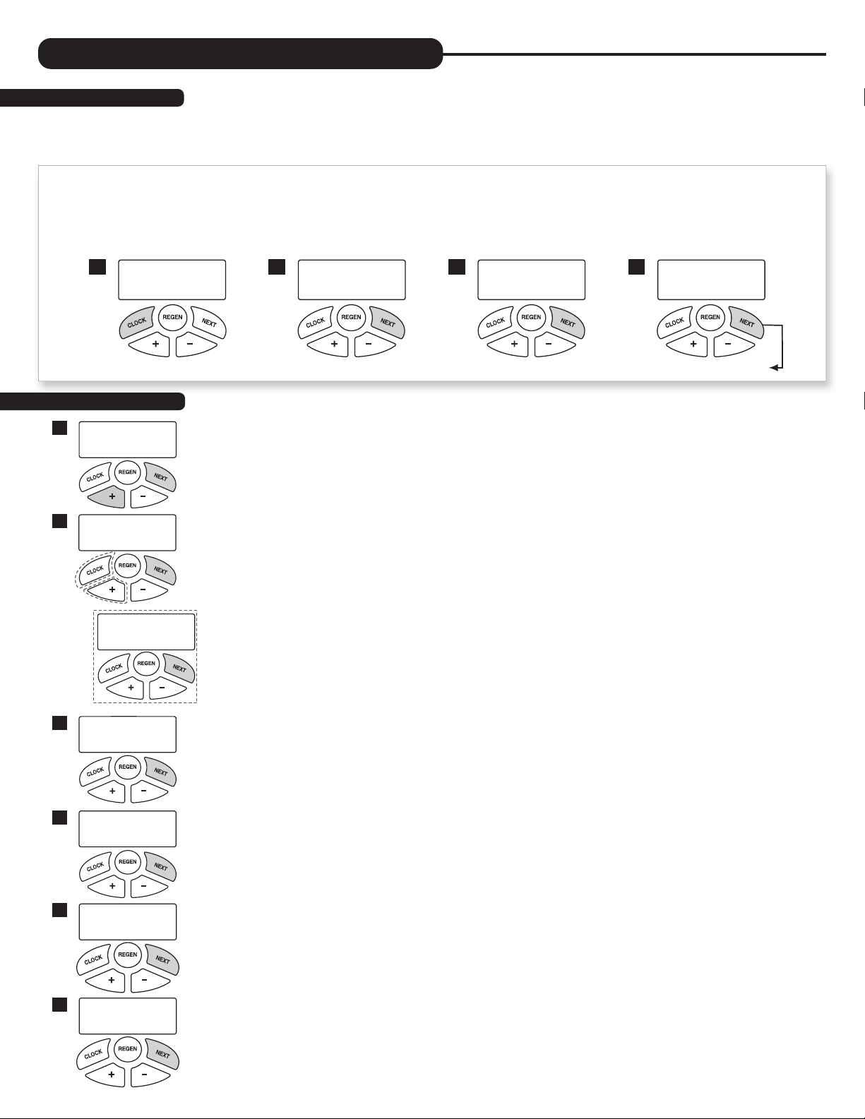
To Advance in Backwash Air Cycle:
1. Pushing the button will advance to each of the twelve
mini steps within the backwash air cycle. While there are
usually twelve steps to this cycle, the valve may make two or
three movements for each step. Wait for these movements
to complete before pressing again.
2. Pushing and holding the button for three seconds
while in the Backwash Air cycle will skip the remaining mini
steps and proceed to the next cycle of regeneration which
is usually Backwash.
The system is now ready for filling with water and for testing for Air Filters.
NOTE: The “filling” sequence below represents the start-up procedure for Air Filters.
1. Place the bypass valve into the bypass mode (Fig. 2 on page 4).
2. Press and hold the button until the motor starts. Release button. Put the valve into “BACKWASH” position.
(Please see note above.) Unplug the transformer so that the valve will not cycle to the next position. Open the
inlet handle of the bypass valve very slightly allowing water to fill the tank slowly in order to expel air.
CAUTION: If water flows too rapidly, there will be a loss of media to the drain.
Certain medias such as carbon, or other dry medias, should not be backwashed immediately for extended periods of time. These
medias need to “soak” in the water for a 24-hour period prior to full backwash conditions.
Dry media exposed to water too quickly in backwash will result in media plugging the drain and valve assembly.
3. After the water is flowing steadily to the drain, clear and without the presence of air, slowly open the inlet valve. Restore power and
momentarily press the button to advance the control to the “REGENERANT DRAW DOWN” position.
4. With the bypass still in the diagnostic mode (Fig. 3 on page 4), there should be a slow flow to the drain.
5. Press button in sequence until display returns to “TIME.” Place bypass valve in the normal operating mode
(Fig. 1 on page 4) by opening the outlet bypass handle.
6. CONDITIONING OF MEDIA:
To flush any remaining debris and air from the system again:
1. Turn on a cold water faucet wide open, preferably at a laundry sink or bathtub without an aerator.
2. Wait two to three minutes or until water runs clear, then turn water off.
3. Turn on hot water and check for air, then turn water off after air is discharged.
7. Place unit into regeneration and allow to complete a full cycle. Upon completion, unit will deliver treated water.

11
OPERATING DISPLAYS AND MAINTENANCE
The air sulfur and air iron filter systems look and function much like any backwashing whole house filter; however, unlike these conventional filters,
they use air as a regenerant. This atmospheric air (containing oxygen) helps convert iron or hydrogen sulfide into particles. These filters capture the
particles of iron or hydrogen sulfide gas within the filter media. Your dealer has recommended the proper media depending on your local water
conditions. In some cases where an acidic water condition (low pH) is present, the media may need to be periodically replenished if using this filter
to raise the pH to an acceptable level. Consult dealer for this service. The system is pre-factory set to regenerate every (3) three days at midnight.
The frequency and start time of backwash/regeneration is adjustable to meet local operating conditions and contaminant levels. Total backwash and
recharge time may vary between one half hour to one hour and fifteen minutes depending on the unit configuration
1. GENERAL OPERATION: When the system is operating, one of six displays may be shown and will alternate with the installing dealer’s name
and phone number for future service. Pressing NEXT will alternate between the displays.
1. Time of Day Screen: Displays the current time of day, the day of the week, and flow rate.
2. Flow Rate Screen: Displays the current treated water flow rate through the system in Gallons Per Minute.
Allows the system to be “shut down” when there will be no water usage for an extended period of time.
4. Capacity Remaining Screen: Displays the amount of gallons of treated water remaining until the system triggers a regeneration.
5. Days to a Regen Screen: Displays the number of days until the system triggers a regeneration. Based on the days override value.
6. Dealer Name Screen: Displays dealer specific name and phone number. This scrolling display will only appear if set by the dealer.
If the system has called for a regeneration that will occur at the preset time of regeneration, the words “REGEN TODAY” will appear on the display.
If a water meter is installed, “GPM” flashes on the display when water is being treated, indicating gallons per minute flowing through the system.
2. VACATION MODE: This feature may be used to “shut down” the system for a period of time by preventing the unit from regenerating. The
manufacturer has factory set “OFF” as the default. Turn feature “OFF” or “ON” using the +or –buttons. When turned “ON”, the unit will remain
in Vacation Mode until it is exited. There are two ways that a unit can exit Vacation Mode:
Manually: The user may manually exit Vacation Mode by changing the setting from “ON” to “OFF”. Once switched off, a delayed
regeneration will queue for that night. Vacation mode may also be manually exited by holding the REGEN button to force an immediate
regeneration.
Automatically: The unit will automatically exit Vacation Mode once water usage has resumed. After fifty gallons of water is used, the unit
will set to resume normal operation and a delayed regeneration will queue for that night.
the unit will trigger an immediate regeneration instead of a delayed regeneration. For example, if the unit’s maximum Days
CAUTION: Depending on the severity of water conditions and the length of no water usage, it may not be recommended to use this
feature. Please contact dealer or manufacturer for more information.
3. REGENERATION MODE: Typically, a system is set to regenerate at a time of no water usage.
If there is a demand for water when the system is regenerating, untreated water will be delivered.
When the system begins to regenerate, the display will include information about the step of the
regeneration process and the time remaining for that step to be completed. The system runs through
the steps automatically and will reset itself to provide treated water when the regeneration has been
completed.
TIME OF DAY MON
GPM
2:408
PM
FLOW RATE
GPM
8.0
ON VACATION
NO
CAPACITY REMAINING
GPM GAL
1600
8
DAYS TO A REGEN
GPM
3
8
PHONE NUMBER
DEALER NA
1
4
2
2
5
3
6
REGENERATION MODE
BACKWASH
8:22
Current Regen
Cycle Stage
Time Remaining
in Stage

12
OPERATING DISPLAYS AND MAINTENANCE
4. MANUAL REGENERATION: Sometimes there may be a need to regenerate a unit before the control valve
calls for it. This may be needed if a period of heavy water use is anticipated.
• To initiate a manual regeneration at the next preset regeneration time, press and release the REGEN
button. The words “REGEN TODAY” will flash on the display to indicate that the system will regenerate
at the scheduled regeneration time (see the Programming Procedures section). If you pressed the
REGEN button in error, pressing and releasing the button again will cancel the command.
• To initiate a manual regeneration immediately, press and hold the REGEN button for three seconds. The
system will begin to regenerate immediately. This command cannot be canceled.
Once a manual regeneration is initiated, the unit will enter the first regeneration cycle position. Once the unit advances to its first position and
subsequent positions thereafter, (see Start Up Instructions for regeneration sequence)
the water filter will deliver water, but it will be untreated.
5. POWER LOSS AND BATTERY REPLACEMENT: If an extended power outage occurs, the
control valve will retain the time of day settings until the board’s battery is depleted. Once the
battery is depleted, the display will appear dark and absent of any information. If this occurs,
following these steps will determine if the problem is a low battery or a board failure.
To determine if the battery is depleted:
1. Remove valve cover. Disconnect power from PC Board at the four pin connector at the
bottom of the board.
2. Wait five minutes for board to de-energize. Remove battery with a non-conductive/non-
metallic material. Reference the Parts Breakdown section of this manual for location.
3. Wait five minutes for board to de-energize.
4. With the battery out, re-connect the power supply to the board. The board’s display
should begin to show information.
This indicates that the board is operating correctly. If the display does not work, call installing dealer for service.
5. To replace with new battery, unplug transformer from outlet. Install a 3 volt Lithium Coin Cell type 2032 battery, available at most stores.
Plug unit back into outlet.
It is important to replace the battery with the valve unplugged to avoid causing a short and potentially ruining the board.
6. Reset the time of day (see programming procedures) and initiate regeneration (see operating displays and maintenance).
If these procedures do not remedy the problem, please consult the installing dealer for service.
6. AUDIBLE ALARM: This control valve is equipped with an audible alarm and visual alarm. This alarm is set by the installing dealer and is used to
warn the owner of possible valve errors or other issues.
To turn off alarm: If the audible alarm sounds, press any button on the face of the control valve to turn off and call the dealer for service.
7. ERROR MESSAGE: If the word “ERROR” appears and flashes alternately with the dealer name and phone
number, record the ERROR number and contact your servicing dealer promptly. This indicates that the control
valve was not able to function properly.
8. OZONE GENERATOR AND MAINTENANCE (OPTIONAL FEATURE): In severe cases
where nuisance bacteria* conditions exist, the dealer may have installed an ozone generator
(Part # 100349795, OZ1-A). While these bacteria are harmless to human health, they can produce
a slime and occasionally a taste and odor problem that can be a “nuisance”. The ozone generator
produces a controlled amount of ozone which is introduced to the tank during the regeneration
cycle. This ozone will reduce the slime build up that can occur within the system and also reduce the
associated taste and odors.
The ozone generator is a serviceable item. For optimal
performance, yearly replacement of the ozone check valve
and injector is necessary. Over time, ozone generator cells
become clogged with debris, lose their capability, and require
replacement. When an ozone generator fails due to the need of
cell replacement, it will trigger an alarm in the system. A “Service
Ozone” indicator will appear on the screen of the valve controller
which signals that a cell needs replacement or a potentiometer
adjustment.
This maintenance should be performed by the servicing dealer. Contact dealer for more information.
*Nuisance bacteria refers to iron and sulfate reducing bacteria which is harmless to human health, however can cause
slime, and taste and odor issues.
BATTERY REPLACEMENT
ERROR SCREEN
ERROR
106
CALL FOR SERVICE
OZONE GENERATOR
SERVICE OZONE SCREEN
SERVICE OZONE
MANUAL REGEN
REGEN TODAY MON
GPM
2:408
PM
REGENTODAY and TIMEOFDAY
will flash alternately if a regeneration
is expected tonight.

13
For Automatic Backwash Filters With Dome Hole
1. Check the media height by shining a flashlight through the tank to see
the height of the mineral. If the level is not visible, the top fill plug will have to be
removed (if available) to measure the height. The media tank should only be two-
thirds full (see diagram). Proceed to step 2.
2. To remove top fill plug, turn off the source of the water and open a conditioned
water tap to relieve the water pressure on the system. Place unit into the bypass
mode. Unscrew the top fill plug.
Caution: Never unscrew top fill plug unless pressure is fully released from
system. Serious injury and/or flooding can occur.
3. Siphon out some water from the tank through the dome hole. This will allow room
when adding the media.
4. Add the appropriate amount of replacement media through the dome hole (top fill
plug). Make sure you add the correct amount and type of media (calcite or calcite/
corosex mix). If needed, siphon out more water as the media will displace the water
inside the tank. Pay close attention to media level when filling (see diagram).
Do not overfill. The additional media added should not be higher than two-thirds
of the tank height when measuring from the bottom (see diagram). Once the right
height has been achieved, replace top fill plug. Grease “O” ring if necessary using
only silicone grease.
Tighten appropriately.
5. Leaving controller in the bypass position, turn on water source and refer to the
start-up instructions of the controller and complete the procedure.
6. Once start up is complete, please check the top fill plug for any leaking.
REPLACEMENT MINERAL INSTRUCTIONS
FOR ACID NEUTRALIZERS
Dual Gravel
Under Bedding
Distributor System
Acid Neutralizing Media
Optional Top Fill Plug
100243086 - CQ7006 - Enpress Style
100343241 - CD1338-01 - Clack Style
Fill Level: ²∕³of tank
Acid Neutralizers raise the pH of mildly acidic water. The raising of pH utilizes a sacrificial mineral that will need replenishment every 6 to
12 months. Typically the media should not be below the halfway point in the tank. In order to check the mineral height and before adding
mineral to the system, please follow these instructions.

14
For Acid Neutralizers With the 100245769 (CD1400) In/Out Head Without an Optional Fill Plug
1. Check the media height by shining a flashlight through the tank to see the height of the mineral. To more
clearly check the level of mineral and to fill the tank, the 100245769 (CD1400) In/Out head will need to be
removed.
2. Before removing the head, turn off the water source, open a conditioned water tap to relieve the water
pressure, and then place the unit into bypass mode (see Fig. 2 on page 4).
Caution: Never unscrew in/out head unless pressure is fully released from system. Serious injury
and/or flooding can occur.
3. Unscrew the In/Out head from the tank, disconnecting it from the bypass.
4. Measure media height with ruler.
5. Add appropriate amount of media (calcite or calcite/corosex mix) to no higher than 2/3rds of the tank full.
It may be necessary to siphon out water from the tank as the media will displace it. Take caution to ensure
that no media enters the distributor tube when filling.
6. Re-attach the In/Out Head onto the tank. Apply grease to the O-rings that seal the tank and the distributor.
Only use silicone grease. Never use petroleum based grease such as Vaseline.
7. Re-attach the bypass to the controller.
8. With the controller in the bypass position, open the water source.
9. Open the bypass valve to the normal operating position (see page 4). Inspect valve for any leaks.
10. Open a conditioned water tap and flush until clear.
For Acid Neutralizers With the 100245758 (CD1220) In/Out Head With Fill Port
1. Check the media height by shining a flashlight through the tank to see the height of the mineral. To more
clearly check the level of mineral and to fill the tank, the 100245758 (CD1220) In/Out head top plate will
need to be removed.
2. Before removing the top plate turn off the water source, open a conditioned water tap to relieve the water
pressure, and then place the unit into bypass mode (see Fig. 2 on page 4).
Caution: Never unscrew in/out head unless pressure is fully released from system. Serious injury
and/or flooding can occur.
3. Unscrew the In/Out top plate head from the controller. Remove the top screen located in the controller.
4. Measure media height with ruler.
5. Add appropriate amount of media (calcite or calcite/corosex mix) to no higher than 2/3rds of the tank full
through the in/out fill port. It may be necessary to siphon out water from the tank as the media will displace
it. Take caution to ensure that no media enters the distributor tube when filling.
6. Replace the screen. Re-attach the In/Out top plate. Apply grease to the O-rings that seals the top plate to
the head. Only use silicone grease. Never use petroleum based grease such as Vaseline.
7. With the controller in the bypass position, open the water source.
8. Open the bypass valve to the normal operating position (see page 4). Inspect valve for any leaks.
9. Open a conditioned water tap and flush until clear.
REPLACEMENT MINERAL INSTRUCTIONS
FOR ACID NEUTRALIZERS
CD1400 In/Out Head
CD1220-01 In/Out Head
Top Plate

15
PROBLEM CAUSE CORRECTION
1. No display on
PC board.
A. Depleted battery. A. See Operating Display and Maintenance section.
B. Control valve power adapter not plugged into outlet
or power cord end not connected to PC board
connection.
B. Plug power adapter into outlet or connect
power cord end to PC board connection.
C. Improper power supply. C. Verify proper voltage is being delivered to
PC board.
D. Defective power adapter. D. Replace power adapter.
E. Defective PC board. E. Replace PC board.
F. No power at electric outlet. F. Repair outlet or use working outlet.
2. PC board does not
display correct time
of day.
A. Power adapter plugged into electric outlet controlled
by light switch. A. Use uninterrupted outlet.
B. Tripped breaker switch and/or tripped GFI. B. Reset breaker switch and/or GFI switch.
C. Power outage.
C. Reset time of day. If PC board has battery
back up present the battery may be depleted. See
front cover and drive assembly drawing
for instructions.
D. Defective PC board. D. Replace PC board.
3. Display does not
indicate that water is
flowing. Refer to user
instructions for how
the display indicates
water is flowing.
A. Bypass valve in bypass position. A. Turn bypass handles to place bypass in
service position.
B. Meter is not connected to meter connection on PC
board.
B. Connect meter to three pin connection labeled
METER on PC board.
C. Restricted/stalled meter turbine. C. Remove meter and check for rotation or
foreign material.
D. Meter wire not installed securely into three
pin connector.
D. Verify meter cable wires are installed securely into
three pin connector labeled METER.
E. Defective meter. E. Replace meter.
F. Defective PC board. F. Replace PC board.
4. Control valve
regenerates at wrong
time of day.
A. Power outage.
A. Reset time of day. If PC board has battery
back up present the battery may be depleted. See
front cover and drive assembly drawing
for instructions.
B. Time of day not set correctly. B. Reset to correct time of day.
C. Time of regeneration set incorrectly. C. Reset regeneration time.
D. Control valve set at immediate regeneration. D. Check programming setting and reset to DELAYED
(for a delayed regen time).
5. Time of day flashes on
and off. A. Power outage.
A. Reset time of day. If PC board has battery
back up present the battery may be depleted. See
front cover and drive assembly drawing
for instructions.
6. Control valve does
not regenerate
automatically when
the correct button(s) is
pressed and held.
For timeclock valves
the buttons are +or –.
For all other valves the
button is REGEN.
A. Broken drive gear or drive cap assembly. A. Replace drive gear or drive cap assembly.
B. Broken piston rod. B. Replace piston rod.
C. Defective PC board. C. Defective PC board.
D. Cover installed incorrectly. D. Reinstall cover.
TROUBLESHOOTING GUIDE

16
7. Control valve does
not regenerate
automatically but
does when the correct
button(s) is depressed
and held. For
timeclock valves the
buttons are +or –.
For all other valves the
button is REGEN.
A. Bypass valve in bypass position. A. Turn bypass handles to place bypass in
service position.
B. Meter is not connected to meter connection on PC
board.
B. Connect meter to three pin connection labeled
METER on PC board.
C. Restricted/stalled meter turbine. C. Remove meter and check for rotation or
foreign material.
D. Incorrect programming. D. Check for programming error.
E. Meter wire not installed securely into three
pin connector.
E. Verify meter cable wires are installed securely into
three pin connector labeled METER.
F. Defective meter. F. Replace meter.
G. Defective PC board. G. Replace PC board.
8. Hard or untreated
water is being
delivered.
A. Bypass valve is open or faulty. A. Fully close bypass valve or replace.
B. Media is exhausted due to high water usage. B. Check program settings or diagnostics for abnormal
water usage.
C. Meter not registering. C. Remove meter and check for rotation or
foreign material.
D. Water quality fluctuation. D. Test water and adjust program
values accordingly.
E. No regenerant or low level of regenerant in
regenerant tank. E. Add proper regenerant to tank.
F. Control fails to draw in regenerant. F. Refer to Troubleshooting Guide number 12.
G. Insufficient regenerant level in regenerant tank.
G. Check refill setting in programming. Check refill
flow control for restrictions or debris and, if
necessary, replace.
H. Damaged seal/stack assembly/piston. H. Replace seal/stack assembly and/or piston.
I. Control valve body type and piston type
mix matched.
I. Verify proper control valve body type and
piston type match.
J. Fouled media bed. J. Replace media bed.
9. Control valve uses
too much regenerant.
A. Improper refill setting. A. Check refill setting.
B. Improper program settings.
B. Check program setting to make sure
they are specific to the water quality and
application needs.
C. Control valve regenerates frequently. C. Check for leaking fixtures that may be exhausting
capacity or system is undersized.
10. Residual regenerant
being delivered to
service.
A. Low water pressure. A. Check incoming water pressure – water pressure
must remain at minimum of 25 psi.
B. Incorrect, damaged, or restricted injector. B. Replace injector with correct size for
the application.
C. Restricted drain line. C. Check drain line for restrictions or debris
and remove any obstructions.
11. Excessive water in
regenerant tank.
A. Improper program settings. A. Check refill setting.
B. Plugged injector. B. Remove injector and replace.
C. Drive cap assembly not tightened in properly. C. Re-tighten the drive cap assembly.
D. Damaged seal/stack assembly/piston. D. Replace seal/stack assembly and/or piston.
E. Restricted or kinked drain line. E. Check drain line for restrictions or debris and or
unkink drain line.
F. Plugged backwash flow controller. F. Remove backwash flow controller and replace, if
necessary.
G. Missing refill flow controller. G. Install refill flow controller.
H. Brine tube not inserted properly into brine elbow in
brine tank. H. Install tube all the way into elbow.
PROBLEM CAUSE CORRECTION
TROUBLESHOOTING GUIDE

17
TROUBLESHOOTING GUIDE
12. Control valve fails to
draw in regenerant.
A. Injector is plugged. A. Remove injector and replace.
B. Faulty regenerant piston. B. Replace regenerant piston.
C. Regenerant line connection leak. C. Inspect regenerant line for air leak.
D. Drain line restriction or debris cause excess back
pressure.
D. Inspect drain line and remove to
correct restriction.
E. Drain line too long or too high. E. Shorten length and or height.
F. Low water pressure. F. Check incoming water pressure – water
pressure must remain at minimum of 25 psi.
13. Water running to
drain.
A. Power outage during regeneration.
A. Upon power being restored control will finish
the remaining regeneration time. Reset time of
day. If PC board has battery back up present the
battery may be depleted. See front cover and drive
assembly drawing for instructions.
B. Damaged seal/stack assembly. B. Replace seal/stack assembly.
C. Piston assembly failure. C. Replace piston assembly.
D. Drive cap assembly not tightened in properly. D. Re-tighten the drive cap assembly.
14. E1, Err – 1001,
Err – 101 =
Control unable
to sense motor
movement.
A. Motor not inserted full to engage pinion, motor
wires broken or disconnected.
A. Disconnect power, make sure motor is fully engaged,
check for broken wires, make sure
two pin connector on motor is connected to the two
pin connection on the PC board labeled MOTOR.
Press NEXT and REGEN buttons for
3 seconds to resynchronize software with piston
position or disconnect power supply from PC board
for 5 seconds and then reconnect.
B. PC board not properly snapped into drive bracket.
B. Properly snap PC board into drive bracket and
then Press NEXT and REGEN buttons for 3 seconds
to resynchronize software with piston position
or disconnect power supply from PC board for 5
seconds and then reconnect.
C. Missing drive gears. C. Replace missing gears.
D. Motor does not drive/run. D. Replace motor.
E. Viewing eye or encoder is blocked or damaged. E. clear viewing eye on board, on drive bracket, or
replace PC board if no debris is found.
15. E2, Err – 1002,
Err – 102 = Excessive
Motor Draw.
A. Foreign material is lodged in control valve.
A. Open up control valve and pull out piston assembly
and seal/stack assembly for inspection. Press NEXT
and REGEN buttons for
3 seconds to resynchronize software with piston
position or disconnect power supply from PC board
for 5 seconds and then reconnect.
B. Mechanical binding.
B. Check piston and seal/stack assembly, check
reduction gears, check drive bracket and main drive
gear interface. Press NEXT and REGEN buttons for
3 seconds to resynchronize software with piston
position or disconnect power supply from PC board
for 5 seconds and then reconnect.
C. Drive cap too loose. C. Completely tighten drive cap assembly.
D. Drive cap not “clicked” into backplate. D. Verify that backplate is properly “clicked” into
place.
PROBLEM CAUSE CORRECTION

18
16. E3, Err – 1003,
Err – 103 = Control
valve motor ran
too long and was
unable to find the
next cycle position.
A. Drive bracket not snapped in properly and out
enough that reduction gears and drive gear do not
interface.
A. Snap drive bracket in properly then Press
NEXT and REGEN buttons for 3 seconds to
resynchronize software with piston position
or disconnect power supply from PC board
for 5 seconds and then reconnect.
17. E4, Err – 1004,
Err – 104 = Control
valve motor ran too
long and timed out
trying to reach home
position.
A. Drive bracket not snapped in properly and out enough
that reduction gears and drive gear do
not interface.
A. Snap drive bracket in properly then Press
NEXT and REGEN buttons for 3 seconds to
resynchronize software with piston position
or disconnect power supply from PC board
for 5 seconds and then reconnect.
B. Piston not connected to drive cap. B. Connect or replace (if damaged) piston/drive cap.
18. Err – 1006, Err – 106,
Err – 116 = MAV/
SEPS/ NHBP/ AUX
MAV valve motor
ran too long and
unable to find
the proper park
position.
●Motorized Alternating Valve = MAV
●Separate Source = SEPS
●No Hard Water Bypass = NHBP
●Auxiliary MAV = AUX MAV
A. Control valve programmed for ALT A or B,
nHbP, SEPS, or AUX MAV with out having
a MAV or NHBP valve attached to operate
that function.
A. Press NEXT and REGEN buttons for 3 seconds
to resynchronize software with piston position
or disconnect power supply from PC board for
5 seconds and then reconnect. Then reprogram valve
to proper setting.
B. MAV/NHBP motor wire not connected to
PC board.
B. Connect MAV/NHBP motor to PC board two pin
connection labeled DRIVE. Press NEXT and REGEN
buttons for 3 seconds to resynchronize software
with piston position or disconnect power supply
from PC board for 5 seconds
and then reconnect.
C. MAV/NHBP motor not fully engaged with reduction
gears.
C. Properly insert motor into casing, do not force into
casing Press NEXT and REGEN buttons for
3 seconds to resynchronize software with piston
position or disconnect power supply from PC board
for 5 seconds and then reconnect.
D. Foreign matter built up on piston and stack
assemblies creating friction and drag enough
to time out motor.
D. Replace piston and stack assemblies. Press NEXT
and REGEN buttons for 3 seconds to resynchronize
software with piston position
or disconnect power supply from PC board
for 5 seconds and then reconnect.
19. Err – 1007, Err –
107, Err – 117 =
MAV/ SEPS/NHBP/
AUX MAV valve
motor ran too short
(stalled) while
looking for proper
park position.
●Motorized Alternating Valve = MAV
●Separate Source = SEPS
●No Hard Water Bypass = NHBP
●Auxiliary MAV = AUX MAV
A. Foreign material is lodged in
MAV/NHBP valve.
A. Open up MAV/NHBP valve and check piston and
seal/ stack assembly for foreign material. Press NEXT
and REGEN buttons for 3 seconds
to resynchronize software with piston position
or disconnect power supply from PC board for
5 seconds and then reconnect.
B. Mechanical binding.
B. Check piston and seal/stack assembly, check
reduction gears, drive gear interface, and check
MAV/NHBP black drive pinion on
motor for being jammed into motor body.
Press NEXT and REGEN buttons for 3 seconds to
resynchronize software with piston position or
disconnect power supply from PC board for 5
seconds and then reconnect.
PROBLEM CAUSE CORRECTION
TROUBLESHOOTING GUIDE

19
PROBLEM CAUSE CORRECTION
20. Err – 201
200 errors are only
viewable in history
screens. These do not
flash when error occurs.
A. Invalid regeneration cycle step detected. A. Replace PC board.
21. Err – 202
200 errors are only
viewable in history
screens. These do not
flash when error occurs.
A. Short power disruption. A. Check transformer voltage and verify power source.
B. Foreign material dislodged. B. Check piston and stack for damage.
22. Err – 204 = Leak
detected
200 errors are only
viewable in history
screens. These do not
flash when error occurs.
A. Occurs when dP input is active for “ALARM” and the
input is closed. The alarm buzzer will activate and the
screen will display the error.
A. Check for low flow leak. Press NEXT and REGEN
buttons for 3 seconds to resynchronize software
with piston position or disconnect power supply
from PC Board for 5 seconds
and then reconnect to clear error.
23. Err – 400*
Memory Errors
*All 400 errors pertain to
memory related errors.
400 and 200 errors are
only viewable in history
screens. These do not
flash when error occurs.
A. Depleted Battery. A. See Operating Display and Maintenance section.
B. Defective PC Board. B. Replace PC board.
TROUBLESHOOTING GUIDE

20
REPLACEMENT PARTS
4
1
2
56
3
NOTE: Battery Location
FRONT COVER AND DRIVE ASSEMBLY
Item # Legacy Part # Current Part # Description Qty.
1CV3837-01XC 100244831 Ion Pro®cover, green buttons 1
CV3837-01 100243969 CareSoft Elite/CareSoft Pro cover (blue buttons) 1
2 CV3107-1 100246273 Motor Assembly 1
3 CV3002-A 100246193 Drive assembly (includes #5 and #6) —
4 CV4050WX-02 100246447 PC board 1
CV4237YB-BOARD 100246452 PC board (Wripli-enabled models) 1
5 CV3110 100246279 Drive gear, 12 x 36 3
6 CV3109 100246278 Drive gear cover 1
Not
Shown
CV3186-06 100249863 Transformer, 110V-12V (standard) 1
CV3543 100246379 Optional weather cover 1
This manual suits for next models
1
Table of contents
Other Water Care Water Filtration System manuals
Popular Water Filtration System manuals by other brands

NatureWater
NatureWater 50877 Operation manual

Fernox
Fernox MKIII user guide

Solmetex
Solmetex Hg5 Installation and maintenance instructions

US Water Systems
US Water Systems 320-USP-DS-10 owner's manual

Donaldson Torit
Donaldson Torit WSO M Installation and operation manual

ElectroMaax
ElectroMaax Marine Watermaker Series Installation, operation & maintenance manual