Water Control Corporation MF Series User manual

MF SERIES
WATER SOFTENERS
An Employee-Owned Company
OWNER’S MANUAL
Water Control Corporation
7150 143rd Ave NW •Ramsey, MN 55303
1-866-405-1268 •www.watercontrolinc.com
WC-OM-MF-FRONTPG © Water Control Corporation 030722

An Employee-Owned Company
TABLE OF CONTENTS
WARNINGS......................................................................3
BASIC PRINCIPLES.......................................................... 4
SOFTENING OPERATION..................................................5
SPECIFICATIONS .............................................................6
DIMENSIONS...................................................................8
SET-UP PROCEDURES..................................................... 9
INSTALLATION PROCEDURES.......................................... 10
INSTALLATION DIAGRAMS............................................... 11
WIRING DIAGRAMS.........................................................12
PROGRAMMING INSTRUCTIONS...................................... 14
START-UP PROCEDURES.................................................24
MAINTENANCE PROCEDURES......................................... 27
SERVICE..........................................................................29
TROUBLESHOOTING........................................................ 30
COMPONENTS................................................................. 33
OFFICIAL WARRANTY...................................................... 39
Water Control Corporation
7150 143rd Ave NW •Ramsey, MN 55303
1-866-405-1268 •www.watercontrolinc.com
WC-OM-MF-TOC © Water Control Corporation 030722

An Employee-Owned Company
SYSTEM MUST BE INSTALLED AND MAINTAINED PER THE MANUFACTURER’S
RECOMMENDATIONS IN THIS MANUAL. FALURE TO DO SO MAY CAUSE INJURY, EQUIPMENT
FAILURE AND/OR DAMAGE, AND WILL RESULT IN WARRANTY BEING VOID.
RISK OF SHOCK! ELECTRICAL INSTALLATION SHOULD BE DONE BY QUALIFIED, TRAINED
ELECTRICIANS. INSTALLATION SHOULD BE TO LOCAL CODES.
ALWAYS TURN OFF THE UNIT, SHUT OFF THE FEEDWATER, RELIEVE PRESSURE, AND
DISCONNECT THE ELECTRICAL POWER BEFORE WORKING ON THE UNIT.
DO NOT USE WHERE THE WATER IS MICROBIOLOGICALLY UNSAFE OR OF UNKNOWN
QUALITY WITHOUT ADEQUATE DISINFECTION BEFORE OR AFTER THE SYSTEM.
NEVER ALLOW THE UNIT TO FREEZE OR OPERATE WITH A FEEDWATER TEMPERATURE/
PRESSURE OUTSIDE THE RECOMENDED PARAMETERS (34-110°F / 20-125 PSI).
SYSTEM MUST BE INSTALLED IN ACCORDANCE WITH LOCAL PLUMBING CODES AND
REGULATIONS.CONTACTWCC(WATERCONTROLCORPERATION)FORMOREINFORMATION.
READ THE ENTIRE MANUAL BEFORE INSTALLING, OPERATING, OR MAINTAINING THIS
EQUIPMENT.
THIS SYSTEM CONTAINS FLOWING WATER, UNDER PRESSURE. ENSURE THAT INSTALL
LOCATION HAS ADEQUATE DRAINAGE AND WATERPROOFING TO ACCOMMODATE
POTENTIAL LEAKAGE AND/OR OVERFLOW SITUATIONS. FAILURE TO DO SO COULD RESULT
IN FLOODING/DAMAGE.
WARNINGS
Water Control Corporation
7150 143rd Ave NW •Ramsey, MN 55303
1-866-405-1268 •www.watercontrolinc.com
WC-OM-WRN © Water Control Corporation

Water Control Corporation
7150 143rd Ave NW •Ramsey, MN 55303
Phone: 763-427-9638 •Fax: 763-427-5665
www.watercontrolinc.com ©Water Control Corporation 1021
An Employee-Owned Company
BASIC PRINCIPLES
A water softener works via a process known as Ion Exchange. In this process, a special media bed is used to exchange undesirable hardness minerals,
including calcium, potassium, and magnesium (as well as low levels of iron and manganese) for something more desirable -- in this case, a small amount
of sodium.
A water softener uses a mechanically driven control valve. During normal operation, this valve distributes the ow of raw (hard) water evenly over the
top of the media bed. As the hard water passes down through the media, hardness minerals -- primarily calcium, which exists in solution in a calcium
bicarbonate form -- are removed from solution and axed to the media. In place of this calcium, trace amounts of sodium ions are released. What was
calcium carbonate dissolved in the water becomes sodium bicarbonate (i.e., baking soda).
Once the resin has absorbed all the hardness minerals, and released all the sodium, that it can, regeneration is required. Regeneration is the process of
removing calcium/hardness minerals from the media and resetting it with fresh sodium ions. To achieve this, a piston in the softener control valve changes
position. The media is rst backwashed, to lift and unpack the bed. Next, it is bathed in a supersaturated brine (sodium chloride) solution. This bombards
the media with sodium ions, forcing the calcium/hardness minerals o and sending them down the drain. A relatively small percentage of sodium ions
remain on the media, though the majority pass to the drain as well. After this brine cycle, the media is rinsed o, the brine tank is relled, and the system
goes back into service.
When a single tank water softener regenerates, an internal bypass is opened in the control valve. This allows the facility to be served by hard water during
the regeneration period. Typically, this occurs in the middle of the night (2AM being the standard setting). Multi-tank systems regenerate one tank at a time,
with the non-regenerating tanks remaining online (with no periods of hard water being sent to the facility).
Many multi-tank commercial softening systems feature a Progressive Flow functionality. When building ow rates are low, only one tank is online/active.
As water usage increases, more and more units come online. Conversely, as usage decreases, tanks are progressively removed from service and put back
into standby mode. By bringing tanks on and oine, based on demand, we can maximize the softening capacity and eciency of the media in each tank.
The electronics in the control valves keep track of usage time for each individual tank. Tanks are rotated on and oine in a manner that equalizes usage
across all tanks over the course of 24 hours.
Another common option on larger commercial softening systems is Brine Reclamation, which utilizes an electronic control system and a 3-way motorized
valve to recycle a portion of the supersaturated brine (salt) water that is normally sent down the drain during regeneration. When the recycle interval ends,
the water eventually does go to drain. This ensures fresh brine for each new regeneration. By utilizing Brine Reclamation, a facility will normally see a salt
usage reduction of around 25%-35%, without any negative eects on softener capacity, eciency, or lifespan.
For more information on commercial water softening systems, please visit WCC’s website at: watercontrolinc.com or call us at 763-427-9638.
We thank you for your business!

Water Control Corporation
7150 143rd Ave NW •Ramsey, MN 55303
Phone: 763-427-9638 •Fax: 763-427-5665
www.watercontrolinc.com ©Water Control Corporation 1021
An Employee-Owned Company
SOFTENER OPERATION
As water enters the softener, it passes over a resin bed in a special tank. The resin consists of tiny beads of a plastic called styrene. These beads attract and
hold sodium ions and exchange the sodium for hardness ions when encountered. Over time, the resin becomes saturated with hardness ions and no longer
removes hardness materials. The softener goes into a “regeneration” to ush hardness materials to the drain and refresh the resin with sodium. Regeneration
of single tank systems is typically programmed to take place in the middle of the night when little or no water is in use. Regeneration of individual tanks in
a multi-tank system occurs immediately (as needed), with the other tanks remaining online/ available.
REGENERATION CONSISTS OF FOUR CYCLES:
1. CYCLE: BACKWASH POSITION
Backwash is a rapid upward ow of water that loosens the resin bed and ushes iron particles, dirt and sediments ltered in the bed out to the drain.
2. CYCLE: BRINE DRAW / SLOW RINSE POSITION
Brine Draw is the process in which brine is drawn out of the brine cabinet and passed through the resin in a downward direction. This rinses the resin
and large amounts of sodium ions re- place the hardness ions accumulated during service.
Slow Rinse. After brine is completely removed from the brine cabinet into the resin tank the brine valve closes. Water replaces any remaining brine
from the resin, ushing hardness ions removed from the resin to drain.
3. CYCLE: FAST RINSE POSITION
Fast Rinse is a fast ow of water down through the resin tank that follows a Backwash. This ushes all remaining brine from the tank and packs the
resin bed for softening eciency.
4. CYCLE: BRINE FILL
Brine is water saturated with large amounts of a salt (sodium chloride). During Brine Fill, water ows into the salt storage area after each
regeneration and dissolves salt. During the regeneration process, hardness ions on the resin beads are replaced or exchanged for sodium ions from
the brine solution.
NOTE: SERVICE
When the softener is in service, normal operation is occurring. Water is owing through the softener and hardness minerals are being removed from
the water.

Model
Series
Number
Exchange Capacity*
(grains) Flow Rate (GPM) Pipe Size (in) Back
Wash
(GPM)
Resin
(cu.ft.)
Brine
Tank
Capacity
(lbs)
Regen.
Time
(min)
Tank Size (in) Approx.
Ship
Weight
(lbs)
Min Mid Max Valve
Size (in) Cv 7 psid
Cont.
15 psid
Peak
25 psid Service Drain Resin Salt
MF-48 36800 43200 48000 1.5 8.3 22 32 42 1.5 ⁄ 4 1.6 225 90 12 X 52 18 X 33 150
MF-60 46000 54000 60000 1.5 8 18 28 40 1.5 ⁄ 3 2 225 90 12 X 52 18 X 33 175
MF-90 69000 81000 90000 1.5 8.4 22 30 42 1.5 ⁄ 5 3 650 90 14 X 65 24 X 50 300
MF-120 92000 108000 120000 1.5 9 24 33 45 1.5 ⁄ 7 4 650 92 16 X 65 24 X 50 375
MF-150 115000 135000 150000 1.5 8.2 22 30 41 1.5 ⁄ 5 5 625 94 16 X 65 24 X 50 425
MF-150X 115000 135000 150000 1.5 10.3 28 38 52 1.5 1 8 5 625 96 18 X 65 24 X 50 450
MF-180 138000 162000 180000 1.5 10.2 27 40 51 1.5 1 12 6 600 90 21 X 62 24 X 50 600
MF-210 161000 189000 210000 1.5 10.4 28 40 52 1.5 1 10 7 575 92 21 X 62 24 X 50 650
MF-240 184000 216000 240000 1.5 11.2 30 42 56 1.5 1 15 8 550 94 24 X 72 24 X 50 725
MF-300 230000 270000 300000 1.5 10.8 29 40 54 1.5 1 12 10 500 96 24 X 72 24 X 50 825
- FOR TWIN TANK AND TRIPLEX SYSTEMS, CV RATNGS, EXCHANGE CAPACITIES, FLOW RATES AND RESIN QUANTITIES SHOULD BE DOUBLED OR TRIPLED RESPECTIVELY.
Based on 7 lbs salt per cubic foot.
Based on 10 lbs salt per cubic foot.
Based on 13 lbs salt per cubic foot.
All “MF” Series softeners utilize series 2850 NXT2 controllers.
* Exchange capacity based on treating water with 10 gpg total hardness as CaCo3 and 400 ppm total dissolved solids. Capacities may vary with dierent inuent water characteristics and other factors.
Due to varying water conditions, tank sizes and water pressures, the above should only be used as a guideline.
MF SERIES
WATER SOFTENERS
WCC’s “MF” Series softeners feature 1½” service connections, heavy duty
electronic control valves, high-strength berglass-reinforced mineral tanks,
and long-lasting synthetic cation resin. This series is perfectly designed for
apartments, commercial laundry, schools, hospitals, industrial facilities, and
cooling towers. Available options include single, twin, and triplex systems.
Steel resin tanks, brine reclamation, and Accu-Pipe skid systems are also
available.
SPECIFICATIONS
An Employee-Owned Company
ADVANCED CONTROLLER
· Real-time diagnostics
Flow rates, totalizer, capacity, avg. usage, alarm history, and more
· Remote input for forced regeneration and regeneration lockout
· 2 programmable relays for auxiliary equipment, BAS indication, remote alarms, etc.

WITH OVER 50 YEARS OF EXPERIENCE IN THE WATER CONDITIONING AND PLUMBING INDUSTRIES, WCC CAN DESIGN
AND MANUFACTURE EQUIPMENT FOR VIRTUALLY ANY APPLICATION. WE OFFER A COMPLETE MENU OF SERVICES, INCLUDING WATER TESTING, SYSTEM SIZING, BIM
MODELING (REVIT®), DELIVERY, SETUP, STARTUP, AND AFTER-MARKET SERVICE PLANS. WE MAINTAIN A UNIQUE FOCUS ON MECHANICAL ENGINEERS, CONTRACTORS,
AND THE PLUMBING INDUSTRY. DEPEND ON US TO PROVIDE QUALITY, INNOVATIVE SOLUTIONS FOR ALL YOUR COMMERCIAL WATER CONDITIONING NEEDS.
HOW TO SPECIFY “MF”SERIES SOFTENERS:
ORDER CODE:
MODEL (from other side)
SYSTEM SIZE
Single Tank:
Two Tank*:
Three Tank*:
*Parallel operation only -- no progressive ow option
Additional Options: (check options below)
☐ Brine Reclamation: Re-uses brine solution for signicant salt savings (approx 30%)
☐ Steel Tank(s) (optional ASME Rating)
☐ Accu-Pipe Skid-Mounted System (pre-plumbed**, pre-wired system, mounted on heavy-duty powder-coated steel skid)
☐ Accu-Pipe LS: Same as Accu-Pipe System, less skid base (piping/wiring only)
☐ Brine Silo (large volume salt storage / brine generation & delivery system)
☐ Salt Sock and Access Door (lockable) for blow-in salt delivery
**Standard piping is grooved, type L copper, other materials available.
For a detailed, model-specic specication, please contact WCC (Water Control Corporation). Detailed drawings also available upon request (CAD®or Revit®).
Water softening system requires a minimum inlet water pressure of 30 psig and maximum of 120 psig. If resin tank is subject to vacuum, an adequate vacuum relief valve must be properly
installed. Tank warranty is void if subjected to vacuum. Feed water temperature shall be between 40⁰F and 100⁰F. Each control valve requires a 120 volt wall outlet (2-prong , 1.3FLA, 60Hz).
SIMPLEX (MR)
TWIN
TRIPLEX
MF - -
We look forward to working with you!
Go to www.watercontrolinc.com, where
you’ll nd detailed product specication
info and application design questionnaires.
VISIT US ONLINE
Call 1-866-405-1268 or email
SPEAK DIRECTLY WITH ONE OF
WCC’S DESIGN ENGINEERS
To nd your authorized WCC representative,
please visit: www.watercontrolinc.com/
representative-locator/.
CONTACT YOUR LOCAL
SALES REPRESENTATIVE
Water Control Corporation
7150 143rd Ave NW •Ramsey, MN 55303
1-866-405-1268 •www.watercontrolinc.com
WC-MF © Water Control Corporation 0122

Water Control Corporation
7150 143rd Ave NW •Ramsey, MN 55303
1-866-405-1268 •www.watercontrolinc.com
An Employee-Owned Company
SPECIFICATIONS
All dimensions are approximate and subject to change without notice. Please consult our technical department for additional system information.
Single
Tank (MR) Models
WATER SOFTENER DIMENSIONS
Model
Series
Number
(A) (B) (C) (D) (E) (F)
Resin Tank
Diameter
(+/-0.5 in)
Resin Tank
Height
(+/-1 in)
Inlet/
Outlet
Height
(in)
Overall
Height
(in)
Brine Tank
Diameter
(in)
Overall
Length
(in)
EF-30-MR 10.0 44.6 46.0 57.0 18.0 32.0
EF-48-MR 10.0 47.7 54.0 60.0 18.0 32.0
EF-60-MR 12.0 53.4 55.0 65.0 18.0 34.0
EF-90-MR 14.0 66.1 68.0 78.0 24.0 42.0
EF-120-MR 16.0 66.2 68.0 78.0 24.0 44.0
EF-150-MR 16.0 66.2 68.0 78.0 24.0 44.0
EF-150X-MR 18.0 67.0 69.0 79.0 24.0 46.0
EF-180-MR 21.0 67.0 69.0 79.0 24.0 49.0
XF-30-MR 10.0 44.6 46.0 57.0 18.0 32.0
XF-48-MR 10.0 47.7 54.0 60.0 18.0 32.0
XF-60-MR 12.0 53.4 55.0 65.0 18.0 34.0
XF-90-MR 14.0 66.1 68.0 78.0 24.0 44.0
XF-120-MR 16.0 66.2 68.0 78.0 24.0 44.0
XF-150-MR 16.0 66.2 68.0 78.0 24.0 44.0
XF-150X-MR 18.0 67.0 69.0 79.0 24.0 46.0
XF-180-MR 21.0 67.0 69.0 79.0 24.0 49.0
SF-30-MR 10.0 47.7 50.0 54.0 18.0 32.0
SF-48-MR 12.0 53.4 55.0 60.0 18.0 34.0
SF-60-MR 12.0 53.4 55.0 60.0 18.0 34.0
SF-90-MR 14.0 66.1 68.0 73.0 24.0 42.0
SF-120-MR 16.0 66.2 68.0 73.0 24.0 44.0
SF-150-MR 16.0 66.2 68.0 73.0 24.0 44.0
MF-48-MR 12.0 53.4 55.0 60.0 18.0 34.0
MF-60-MR 12.0 53.4 55.0 60.0 18.0 34.0
MF-90-MR 14.0 66.1 68.0 73.0 24.0 44.0
MF-120-MR 16.0 66.2 68.0 73.0 24.0 44.0
MF-150-MR 16.0 66.2 68.0 73.0 24.0 44.0
MF-180-MR 21.0 67.0 69.0 74.0 24.0 49.0
MF-210-MR 21.0 67.0 69.0 74.0 24.0 49.0
MF-240-MR 24.0 74.2 76.0 81.0 24.0 52.0
MF-300-MR 24.0 74.2 76.0 81.0 24.0 52.0
Model
Series
Number
(con’t)
(A) (B) (C) (D) (E) (F)
Resin Tank
Diameter
(+/-0.5 in)
Resin Tank
Height
(+/-1 in)
Inlet/
Outlet
Height
(in)
Overall
Height
(in)
Brine Tank
Diameter
(in)
Overall
Length
(in)
LF-90-MR 14.0 66.1 68.0 78.0 24.0 42.0
LF-120-MR 16.0 66.2 68.0 78.0 24.0 44.0
LF-150-MR 16.0 66.2 68.0 78.0 24.0 44.0
LF-150X-MR 18.0 67.0 69.0 79.0 24.0 46.0
LF-180-MR 21.0 67.0 69.0 79.0 24.0 49.0
LF-210-MR 21.0 67.0 69.0 79.0 24.0 49.0
LF-240-MR 24.0 74.2 76.0 86.0 24.0 52.0
LF-300-MR 24.0 74.2 76.0 86.0 24.0 52.0
LF-360-MR 30.0 78.9 81.0 91.0 30.0 64.0
LF-450-MR 30.0 78.9 81.0 91.0 30.0 64.0
LF-600-MR 36.0 80.4 83.0 92.0 39.0 79.0
HF-300-MR 24.0 77.0 82.0 92.0 24.0 52.0
HF-450-MR 30.0 79.7 85.0 95.0 30.0 64.0
HF-480-MR 30.0 79.7 85.0 95.0 30.0 64.0
HF-600-MR 36.0 82.3 87.0 97.0 39.0 79.0
HF-810-MR 42.0 72.5 78.0 88.0 39.0 85.0
HF-900-MR 42.0 72.5 78.0 88.0 50.0 96.0
HF-990-MR 48.0 72.5 87.0 97.0 50.0 102.0
HF-1200-MR 48.0 72.5 87.0 97.0 50.0 102.0
HF-1800-MR 63.0 86.0 104.0 114.0 50.0 117.0
We look forward to working with you!
Go to www.watercontrolinc.com, where
you’ll nd detailed product specication
info and application design questionnaires.
VISIT US ONLINE
Call 1-866-405-1268 or email
SPEAK DIRECTLY WITH ONE OF
WCC’S DESIGN ENGINEERS
To nd your authorized WCC representative,
please visit: www.watercontrolinc.com/
representative-locator/.
CONTACT YOUR LOCAL
SALES REPRESENTATIVE
WC-SNG © Water Control Corporation 0222

An Employee-Owned Company
SET-UP PROCEDURES
IInspect distributor assembly inside of each tank for damage. The distributor assembly is shipped secured to the resin tank, but damage can occur during
shipping. If the distributor is damaged, do not ll resin tank with gravel/media as it will need to be removed for distributor repair.
Contact WCC at 763-427-9638.
1. Unpackage the resin tanks and place them into/near their installation location. Leave the knockout plug on the distributor tube. This will be removed
after the gravel/media has been loaded into the resin tanks.
2. Load the gravel into the resin tanks using the supplied funnel. The funnel is shipped in the brine tank. See gravel chart for number of gravel bags per
tank.
3. Load the softening media into the resin tanks using the supplied funnel. The funnel is shipped in the brine tank. See chart for number of resin bags
to install per tank.
4. Remove the knockout plug on the distributor tube.
5. Snap on black deector onto the bottom of valve.
6. Screw valve onto resin tank.
7. Install ow meter on outlet side of the softener valve
8. Contact WCC for setup instructions : (763) 427-9638.
MODEL
SERIES
NUMBER
# OF
RESIN BAGS
(per tank)
# OF
GRAVEL BAGS
(per tank)
MF-48 1.6 0.5
MF-60 2 0.5
MF-90 3 1
MF-120 4 1
MF-150 5 1
MF-150X 5 2
MF-180 6 2
MF-210 7 2
MF-240 8 2
MF-300 10 2
Water Control Corporation
7150 143rd Ave NW •Ramsey, MN 55303
1-866-405-1268 •www.watercontrolinc.com
WC-OM-MF-SETUP © Water Control Corporation 030722
An Employee-Owned Company
INSTALLATION PROCEDURES
1. IDENTIFY INSTALLATION LOCATION FOR WATER SOFTENER. Piping should be such that all hard water, except for outside hydrants, ows through
softener. This system and installation must comply with state and local laws and regulations.
2. CONNECT WATER PIPING. See install diagrams for plumbing layout. Important: Make all sweat-solder connections within 6 inches of softener before
applying threaded ttings. Overheating may cause damage to valve. Note: WCC recommends installing isolation valves on the inlet and outlet of each
control valve, as well as a full system bypass.
3. CONNECT DRAIN LINE. Be sure not to submerse drain line end into drain, as a 1-1/2” minimum air gap must be maintained to prevent potential
backow hazard. Firmly secure at drain, while maintaining a minimum 1-1/2” air gap. Note: Floor drain must be capable of handling full backwash
ow rate (see page 6 for backwash rates).
4. CONNECT BRINE LINE. Connect brine line (supplied in parts bag) to tting on brine tank, and on the control valve. Tighten both ttings with an
adjustable wrench. Note: If you have purchased a setup/startup service, startup agent will connect brine line on site.
5. INSTALL BRINE TANK OVERFLOW LINE. Install overow tting into hole inside of brine tank. An owner-supplied overow line should then be attached
and run to a nearby drain. Failure to run overow line could cause ooding and water damage should the brine tank overow. See the table below
for brine tank overow recommended line size. Note: Line sizes over 0.5 inches are to be hard plumbed to the drain.
6. CONNECT TO ELECTRICAL POWER SOURCE. Connect power cord to a separate 120v, 15-amp, ground fault interrupt (GFI) outlet. Note: Each control
valve should have a dedicated 120V outlet
NOTE: This system is not intended to be used for treating water that is microbiologically unsafe or of unknown quality without disinfection before or
after the system.
Water Control Corporation
7150 143rd Ave NW •Ramsey, MN 55303
1-866-405-1268 •www.watercontrolinc.com
WC-OM-INSTALL © Water Control Corporation
BLFC
(gpm) SOFTENER CAPACITY
(kgrains) BRINE TANK
OVERFLOW (in)
1up to 150 0.5
2150X - 300 0.75
5360 - 600 1
10 800 and up 1.5

Water Control Corporation
7150 143rd Ave NW •Ramsey, MN 55303
Phone: 763-427-9638 •Fax: 763-427-5665
www.watercontrolinc.com ©Water Control Corporation 1121
An Employee-Owned Company
SIMPLEX INSTALLATION DIAGRAM
Date
Drawn by
Simplex
Commercial Softener
Installation Diagram
07/21/2021
TMD
Drain Line
System Inlet
System Outlet
Bypass Valve
Outlet Isolation Valve
Inlet Isolation Valve
Brine Line
Overflow
Resin Tank
Control Valve
Brine Tank
Flow Meter
44404 Rev A
44403 Rev A
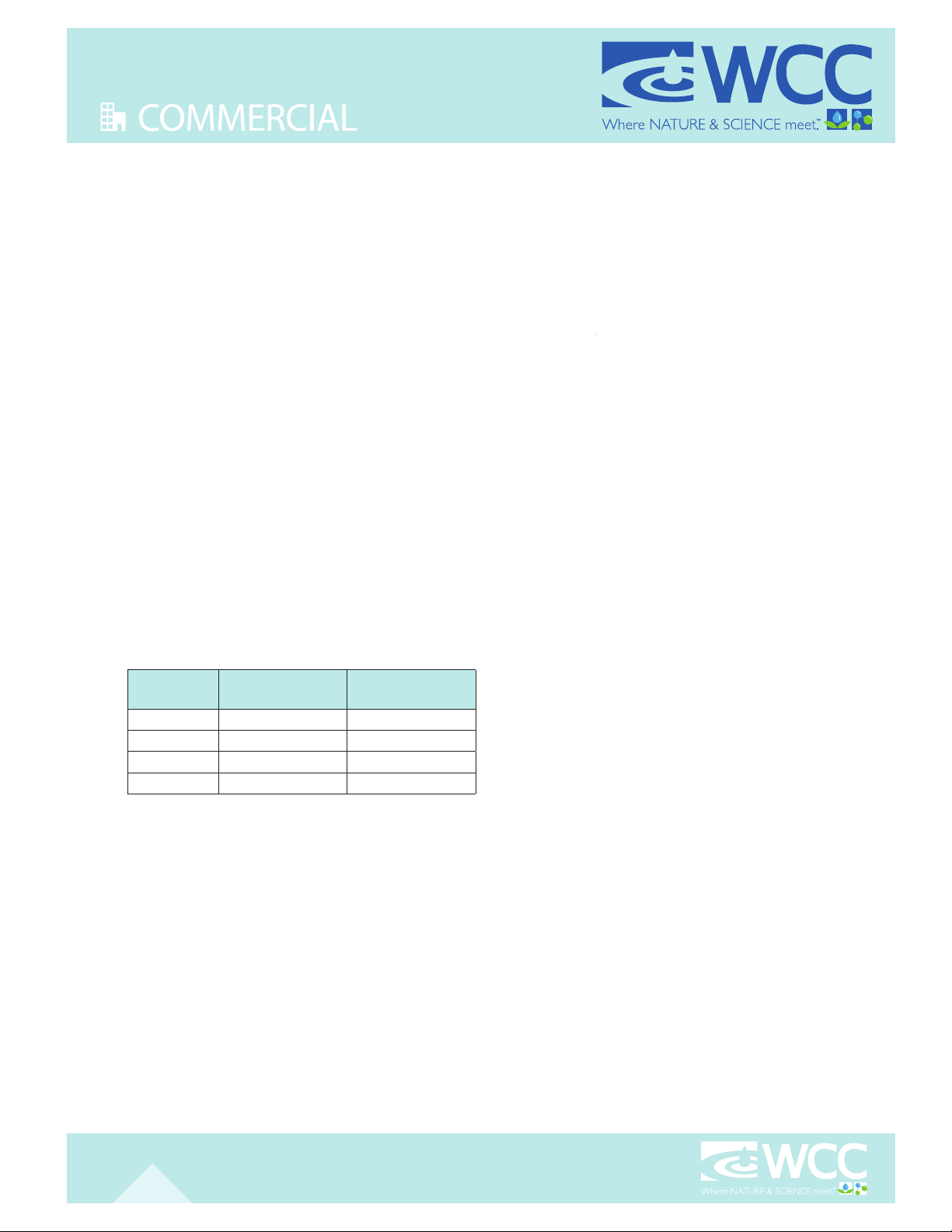
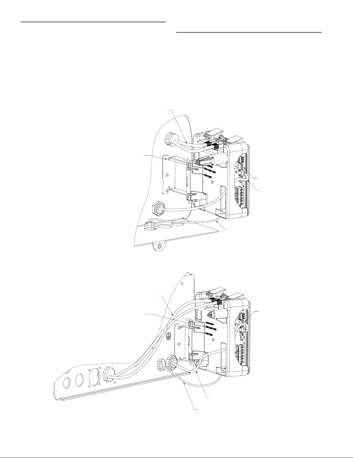
POWER SUPPLY CONNECTIONS
2510/2750/2815/2850/2900 Valves:
3150/3900 Valves:
Installing the Power Supply:
NOTE: Power Supply includes a harness with 2 black wires
that connect to circuit board, see page 15.
1. Insert black and black transformer wires into 24VDC input
of control.
Communication Cables
Hinge Mount: mount per valve model noted
Meter Cable
Power Supply
Wire Harness
Communication Cables
Power Supply
Meter Cable
Wire Harness
Hinge Mount: mount per valve model noted
NETWORK/COMMUNICATION CABLES
AND CONNECTIONS
Use a CAT5 or better Network/Communication cable.
Connect the network/communication cable rst before
programming.
The maximum cable length between timers is 100 feet.
Connect each unit in series (do not form a loop) together from
one communication port to the next communication port. It
does not matter which one goes to the next one.
18 • Fleck NXT2 Timer

WIRING DIAGRAM
VDM
VDM
IMPORTANT: DO NOT USE P18 TO POWER
NON-PENTAIR DEVICES; USE AUX1 & AUX2 INSTEAD

On-screen multilingual support:
English, Franăais, Deutsch,
Italiano, Español, Nederlands,
Português
Time of day super capacitor
backup for 12-hour power loss
2 to 4 line scrolling text OLED
display, high contrast easy to
read in low light conditions and at
a distance
Full functional user interface
with easy programming allowing
forward and backwards menu
navigation
Network two to eight valves via CAT5
or better cables
LED Status Indicator
- Blue: In Service
- Flashing Blue: Regeneration
Queued
- Green: Regeneration
- Flashing Green: Standby
- Red: Error condition present
Two Programmable Auxiliary relay
outputs
- Time-based
- Volume based (Chemical pump)
- Alarm-based
- Cycle-based
- Standby
Remote input
- Remote Lockout
- Remote Regeneration
Easy installation with plug-in wiring
harnesses
Assistance Name and Phone Number
³®ÈvÈï¨Ã
Error Log History
Water Usage Daily (up to 13 weeks)
Push Settings
Capacitive Touch buttons
Two Regeneration Lockout Windows
Reset to factory default settings or
from savable custom settings
Full calendar display
Master Programming Lockout
- Code-based
- Time-based
- Delayed
Icons for easy system status
®Èïvȳ®
Dynamic network addressing
Diagnostics
- Real-time Flow Rate
- Peak Flow Rate (can be reset)
- Totalizer (can be reset)
- Reserve Capacity
- Use Since Last Regeneration
- Last Regeneration
ư *®Èïv¨O³ÈÜvÀ_Àó®
- Total Number of Regenerations
- Regeneration Interval
- Last Settings Change
- Error Log History
- Average Daily Usage
(per weekday, 3 month history)
NXT2 CONTROLLER
ADVANCED SYSTEM NETWORK CONTROLLER
NXT2 CONTROLLER SPEC SHEET WATERPURIFICATION.PENTAIR.COM
Coated Stock - CMYK
FEATURES • BENEFITS
FLECK
4FDUJPO1SPHSBNNJOH*OTUSVDUJPOT

4005307 Rev A JL18
13845 Bishops Dr. |Suite 200 |À³³§ï¨Ɯ`*űůŬŬű|V®ÈOÈvÈÃ
P: 262.238.4400 |ËÃȳÀvÀƝŴŬŬƛŮųŵƛŵŰŬŰ|ÈưÃ˽½³ÀÈǩ½®ÈvÀƛ³
§$³ÀvÈv¨¨ÃȳÜÀI®ÈvÀÈÀvvÀ§ÃvÀÀÃÈÀƜ½¨vÃÛÃÈÜvÈÀ½ËÀïvȳ®ƛ½®ÈvÀƛ³ƨÀv®Ãƛ
I®ÈvÀÈÀvvÀ§Ãv®¨³³ÃvÀ³Ü®âI®ÈvÀ½¨³ÀÈÃví¨vÈÃƛSÀ½vÀÈâÀÃÈÀv®Ë®ÀÃÈÀ
ÈÀvvÀ§Ãv®¨³³ÃvÀȽÀ³½ÀÈâ³ÈÀÀýÈ۳ܮÀÃƛ
ǭŮŬŭŴI®ÈvÀLîÈv¨$¨ÈÀvȳ®Ɯ44ƛ¨¨ÀÈÃÀÃÀÛƛ
13845 Bishops Dr. |Suite 200
À³³§ï¨Ɯ`*űůŬŬű|V®ÈOÈvÈÃ
P: 262.238.4400 |ËÃȳÀvÀƝŴŬŬƛŮųŵƛŵŰŬŰ
ÈưÃ˽½³ÀÈǩ½®ÈvÀƛ³
§For a detailed list of where Pentair trademarks are registered, please
ÛÃÈÜvÈÀ½ËÀïvȳ®ƛ½®ÈvÀƛ³ƨÀv®ÃƛI®ÈvÀÈÀvvÀ§Ãv®
¨³³ÃvÀ³Ü®âI®ÈvÀ½¨³ÀÈÃví¨vÈÃƛSÀ½vÀÈâÀÃÈÀ
v®Ë®ÀÃÈÀÈÀvvÀ§Ãv®¨³³ÃvÀȽÀ³½ÀÈâ³ÈÀ
ÀýÈ۳ܮÀÃƛ
ǭŮŬŭŴI®ÈvÀLîÈv¨$¨ÈÀvȳ®Ɯ44ƛ¨¨ÀÈÃÀÃÀÛƛ
SYSTEM SYSTEM DESCRIPTION NUMBER OF TANKS/CONTROLS TYPE
4 Single Unit 1
Time Clock: No Meter
Immediate: One Meter
Delayed: One Meter
Remote: No Meter
5 Interlocked From 2 up to 8 Immediate: All Meters
Remote: No Meter
6Series
Regeneration From 2 up to 8
Immediate: One Meter
Delayed: One Meter
Remote: No Meter
7Twin
Alternaiting 2
Immediate: One Meter
Remote: No Meter
8 Alternating Delayed 2 Immediate Transfer, Delayed Regeneration
9Multiple Tank
Alternating From 2 up to 8
Immediate: All Meters
Remote: No Meter
14 Demand Recall From 2 up to 8 Immediate: All Meters
VALVE SPECIFICATIONS
System Type 4, 5, 6, 7, 8, 9, 14
SPECIFICATIONS
VALVE TYPE
2750
2850
2900s
3150
3900
2815
REGENERATION TYPE
Meter Delayed Fixed Reserve
Meter Immediate
Remote Signal Start Immediate
Time Clock Delayed
REGENERATION TYPE
³Ü®ð³Ü
V½ð³Ü$¨¨$ÀÃÈ
V½ð³ÜÀ®$ÀÃÈ
ELECTRICAL RATING
24V DC Power Supplies
100V-240V AC input; 24V DC output
GENERIC METER GUIDELINES
Open collector output
Pulse rate generated must not exceed 100 pulses per
second (100Hz) or 6,000 pulses per minute
Support for meter outputs in the range of 1-255 gallons
(25.5m3) for every 1-255 pulses
Meter must operate at 5 VDC

Display Icons
Valve State: Service
Valve State: Standby
Flow Indicator (flashing)
Regeneration
Master Unit (auto-assigned)
Network Indicator - Connected
Network Indicator - Disconnected
Network Indicator - Unit Missing
USB Connected (Field Programmer)
Error Condition Present
Remote Lock
Lock Window
Initializing
Upper Drive Movement
Lower Drive Movement
Remote Regeneration
Master Programming
User Programming
Diagnostics
Time of Day Programming
TIMER DISPLAY
System
Number
Network
Indicator
Valve
State
Flow
Indicator
Time
of Day
Master
Indicator
Status
LEDs
Display Screen
Alternates between
Date, Flow Rate, and
Volume Remaining
(If a regeneration is
queued, displays time
until regeneration)
Left Button
Press:
Navigate to previous
menu option
Press and Hold:
Enter Diagnostic menu
Blue LED
On - Unit in Service
Blinking - Regeneration Queued
Green LED
On - Unit in Regeneration
Blinking - Unit in Standby
Red LED
On - Error present
Down Button
Press:
Adjust menu value down
Press and Hold:
Enter Time of Day menu
Up Button
Press:
Adjust menu value up
Press and Hold:
Enter Time of Day menu
Left Button + Down Button
Press and Hold -
Enter Master Programming
Down Button + Up Button
Press and Hold -
Enter User Programming
Extra Cycle Button
Press:
Navigate to next
menu option
Press and Hold:
Initiate a regeneration
Fleck NXT2 Timer

TIMER OPERATION
Setting the Time of Day
NOTE: Set Time of Day on any unit and the rest of the units in
the system will update the Time of Day automatically.
1. Press and hold the Up button for 2 seconds.
The "Time" value is displayed. Press the Up or Down
buttons to adjust as desired.
2. Press the Extra Cycle button to advance to the "Year" field.
Press the Up or Down buttons to adjust as desired.
3. Press the Extra Cycle button to advance to the "Month"
field. Press the Up or Down buttons to adjust as desired.
4. Press the Extra Cycle button to advance to the "Calendar
Day" field. Press the Up or Down buttons to adjust as
desired.
5. Press the Extra Cycle button to return to the normal display
screen.
NOTE: Press and hold the Left button to exit without saving.
Manually Initiating a Regeneration
1. When timer is In Service or Standby, press and hold the
Extra Cycle button on the main screen.
2. The timer advances to Regeneration Cycle Step #1, and
begins programmed time count down.
3. Press the Extra Cycle button once to advance valve to
Regeneration Cycle Step #2 (if active).
4. Press the Extra Cycle button once to advance valve to
Regeneration Cycle Step #3 (if active).
5. Press the Extra Cycle button once to advance valve to
Regeneration Cycle Step #4 (if active).
6. Press the Extra Cycle button once to advance valve to
Regeneration Cycle Step #5 (if active).
7. Press the Extra Cycle button once more to advance the
valve back to In Service.
NOTE: A manually initiated or queued regeneration can be
cleared by pressing and holding the Back button.
A system queued regeneration can only be cleared
by stepping through a manual regeneration. If
regeneration occurs for any reason prior to the
delayed regeneration time, the manual regeneration
request shall be cleared. Pressing the Extra Cycle
button while in regeneration will cause the upper
drive to advance to the next step immediately.
Timer Operation During Regeneration
In the Regeneration Cycle step display, the timer shows the
current regeneration cycle name the valve is in, or has reached,
and the time remaining in that step. Once all regeneration
steps are complete, the timer returns to In Service and
resumes normal operation.
CYCLE 1/5
BACKWASH 00:10:00
CYCLE 2/5
DRAW 00:60:00
CYCLE 3/5
RAPID RINSE 00:10:00
CYCLE 4/5
TANK REFILL 00:12:00
3UHVVWKH([WUD&\FOHEXWWRQGXULQJDV\VWHP
TXHXHG5HJHQHUDWLRQ&\FOHWRLPPHGLDWHO\
DGYDQFHWKHYDOYHWRWKHQH[WF\FOHVWHSSRVLWLRQ
DQGUHVXPHQRUPDOVWHSWLPLQJ
Timer Operation During Programming
The timer enters the Program Mode in Standby or Service
Mode as long as it is not in regeneration. While in the Program
Mode, the timer continues to operate normally monitoring
water usage. Timer programming is stored in memory
permanently.
Timer Operation During A Power Failure
All program settings are stored in permanent memory. Current
valve position, cycle step time elapsed, and time of day are all
stored during a power failure, and will be restored when power
is re-applied. Time is kept during a power failure, and time of
day is adjusted upon power up (as long as power is restored
within 12 hours).
NOTE: The time of day on the main display screen will flash
for 5 minutes when there has been a power outage.
The flashing of the time of day can be stopped by
pressing any button on the display.
Flow Meter Equipped Timer
As treated water is used, the Volume Remaining display counts
down from the calculated system capacity to zero. When zero
is reached, a Regeneration Cycle begins if no other units are in
regeneration.
Fleck NXT2 Timer

TIMER FEATURES
Regeneration Types
Softener/Filter Meter Delayed - When volume remaining
reaches zero and the scheduled regeneration time is reached
(default 2 a.m. softener; 12 a.m. filter), the unit will regenerate.
Softener/Filter Meter Immediate - When volume remaining
reaches zero, the unit will regenerate.
Time Clock - Once volume remaining reached zero and the
selected regeneration time is reached (default 2 a.m. softener;
12 a.m. filter), the unit will regenerate.
Day of the Week - Once volume remaining reaches zero and the
selected Day of the Week is reached, the unit will regenerate.
Remote Regeneration - Regeneration begins or is queued
after a contact closure meets or exceeds for the length of
time specified in the Remote Signal Duration (Range 1-30
seconds Service; 60-300 seconds Standby). Unit regenerates
will occur based on the Remote Regeneration specified
method (Immediate or Delayed). Immediate Regeneration will
immediately initiate a regeneration. Delayed Regeneration will
initiate a regeneration based on the programmed regeneration
time selected.
Reset to Factory Defaults
While powering up the unit, when the Pentair logo appears,
press and hold the Extra Cycle button to access the Reset
menu then select Reset to Factory Defaults. Press the Extra
Cycle Button to confirm your selection and to advance to the
service screen. Furthermore, you may select
Reset to Non-Factory Defaults to save a set of unique control
parameters.
RESET
PRESS & HOLD
BACK
RESET TO FACTORY DEFAULTS
RESET TO NON-FACTORY DEFAULTS
END
Power on the unit.
When Pentair logo appears,
press and hold the Extra Cycle button.
The Reset menu appears.
Use the up/down buttons to select.
Press the Extra Cycle button to set the
desired option and return to the
Service screen.
Lock Window
Lock Window prevents the unit from regenerating during a
specified time frame. Two lock windows are available (Lock
Window #1 and Lock Window #2). In Master Programming,
enable a Lock Window then select the desired Lock Start time
and Lock End time.
Settings Review
To prevent unintentional changes to Master Programming,
enable Settings Review to view and navigate through Master
Programming settings without the ability to edit.
Remote Lock
The timer does not allow the unit/system to go into
Regeneration until the Regeneration Lockout Input signal to the
unit is cleared. This requires a contact closure to activate the
unit. The recommended gauge wire is 16 AWG with a maximum
wire length run of 50 feet.
Regeneration Day Override Feature
If the Day Override option is turned on and the valve reaches
the set Regeneration Day Override value, the Regeneration
Cycle starts if no other unit is in Regeneration. If other units
are in regeneration, it is added to a regeneration queue. This
occurs regardless of the remaining volume available.
Lock Settings (access to Master Programming)
Lock Settings prevents the user from accessing Master
Programming. In Master Programming, select the desired Lock
Settings option (Off, Time Based, Delayed, or Enter Code).
Time Based - User must set clock to 12:01 pm to unlock
Delayed - User must press and hold the Left and Down buttons
for 60 continuous seconds to unlock
Enter Code - User must input code "1201" to unlock
Capacitive Buttons
Capacitive button entry warrant different consideration than
tactile button entry. Do not wear gloves. Be sure to keep
your hands and the capacitive buttons free of debris, grease,
or water. Buttons may become temporarily unresponsive if
environmental conditions change such as sudden humidity or
temperature changes. If buttons become unresponsive, wait 5
to 10 minutes for the buttons to recalibrate.
LED Status indicator
Blue - Unit in Service
Flashing Blue - Regeneration Queued
Green - Regeneration
Flashing Green - Standby
Red - Error with codes
Power Loss Backup
Time of day super capacitor backup for power loss; rated to
last minimum 12 hours
Continuous Flow Detect
Alert appears when specified continuous flow rate is detected
during service over a specified duration. Continuous flow rate
is adjustable from 0.1 to 999.9 GPM/LPM (accuracy of flow rate
detected will vary based on capability of meter). Duration range
is adjustable from 1 to 255 hours.
Remote Regeneration
Ability to trigger a regeneration via a remote input.
Fleck NXT2 Timer

Auxiliary Relays
The NXT2 has two auxiliary relays available based on cycle,
time, or volume.
Activates during selected cycle step
Activates upon selected start time
(Range: 0-91 minutes)
Deactivates upon selected end time
(Range: Start Time plus 1 minute)
Activates when selected volume (gallon)
is reached (Range: 0-99999)
Selected Duration in Seconds
(Range: 0-9999 seconds)
AUX.1: CYCLE BASED
SP BW BD RR RF SB
AUX.1:TIME BASED-START TIME #1
1 M
AUX.1:TIME BASED-END TIME #1
5 M
AUX.1:VOLUME BASED - VOLUME-G
00100
AUX.1:VOLUME BASED - DURATION-S
0010
TIMER FEATURES continued...
Push Settings
The ability to transmit settings from one unit to all other
connected units. Select the desired Master Programming
settings on one unit then push the same settings to all other
connected units. After push settings are complete, you may still
make unique changes to individual units.
Fleck NXT2 Timer

SYSTEM DEFINITIONS
System 14 (2-8 Units) Demand Recall
Meter input is required on each tank. Unit #1 will begin In
Service with #2, #3, and #4 (if installed) will begin in Standby.
At least one unit is In Service at all times. When flow rate to the
Primary Service Unit increases to a user specified rate, the
next unit in sequence will move from Standby to Service. As
the flow rate falls below the user specified rate, subsequent
tanks will return to Standby. When the Primary Service Unit
regenerates, the next unit in sequence will becomethe new
Primary Service Unit. As each units capacity is reached, the
controller will initiate a Regeneration of that unit. Depending
on the number of units in the system and flow rate demand,
the regenerated unit will then be placed either into Standby or
Service. Only one unit will be in Regeneration at a time.
System 4 - Single Unit
Single Tank configuration Time Clock: No Meter Immediate: One
Meter Delayed: One Meter Remote Signal Start
System 5 (2-8 Units) Parallel Interlock)
All tanks in parallel supplying treated water. Each unit in the
system will have its own flow meter/sensor input. The control
will delay the start of Regeneration if another unit is already
in Regeneration. Once that unit has completed a Regeneration
cycle, and has returned to Service, the unit with the longest
regeneration queue time will begin Regeneration. No more than
one unit will be in Regeneration at at time.
System 6 (2-8 Units) Parallel Series Regeneration
All tanks in parallel supplying treated water. Only #1 control
will monitor flow meter/sensor input. When a regeneration is
required for the system, it will regenerate valve address #1
first, immediately followed by #2, then #3, then #4 if installed.
No more than one unit will be in Regeneration at a time.
System 7 (2 Units) Alternating Immediate
One tank online supplying treated water, one tank in Standby.
Only #1 control will monitor its flow meter/sensor input.
Regeneration of a unit will begin after the other control has left
Standby and returned to Service. When the Regeneration cycle
is complete, the regenerated unit will enter Standby. Standby
on each tank is controlled by the relay on the NXT2 circuit
board.
System 8 (2 Units) Alternating Delayed
Immediate Transfer Delayed Regeneration One tank online
supplying treated water, one tank in Standby. Only #1 control
will monitor its flow meter/sensor input. Online unit depletes
its volume. Once this occurs the offline unit comes online. The
previously online unit goes offline and delays its regeneration
until the programmed regeneration time has been reached.
System 9 (2-8 Units) Alternating with Standby
Units
Up to 7 tanks online supplying treated water, one tank
in Standby. Meter/sensor input is required on each tank.
Regeneration of a unit will begin after the other control has left
Standby and returned to Service. When the Regeneration cycle
is complete, the regenerated unit will enter Standby. Standby
on each tank is controlled by the relay on the NXT2 circuit
board.
Fleck NXT2 Timer
This manual suits for next models
10
Table of contents
Other Water Control Corporation Water Filtration System manuals


Popular Water Filtration System manuals by other brands

Vizion
Vizion TAP-42x Series owner's manual

Adey
Adey MagnaClean Micro2 Installation and servicing

Water Right
Water Right ECLIPSE WRO-35 Installation, operation & service manual

Kessel
Kessel NS 2 MANUAL FOR INSTALLATION, OPERATION AND MAINTENANCE

Du Pont
Du Pont QuickTwist WFRO60X-1 Series installation instructions

CAB
CAB MAESTRO 3E/450 Operator's manual


