Water Control Dakotah series User manual

Metered Water Softener
Installation / Operation Manual

2
For help with installation
or troubleshooting
please contact
Water Control Corporation.
Water Control Tech Services Department:
Toll Free: 1-866-405-1268
Local: 763-427-9638
Fax: 763-427-5665
3
Installation Procedure
1. Identify installation location for water softener. Piping should be such that all household water, with the
exception of outside hydrants, flows through softener. A hard water line may be run to a kitchen tap if so
desired. This system and installation must comply with state and local laws and regulations.
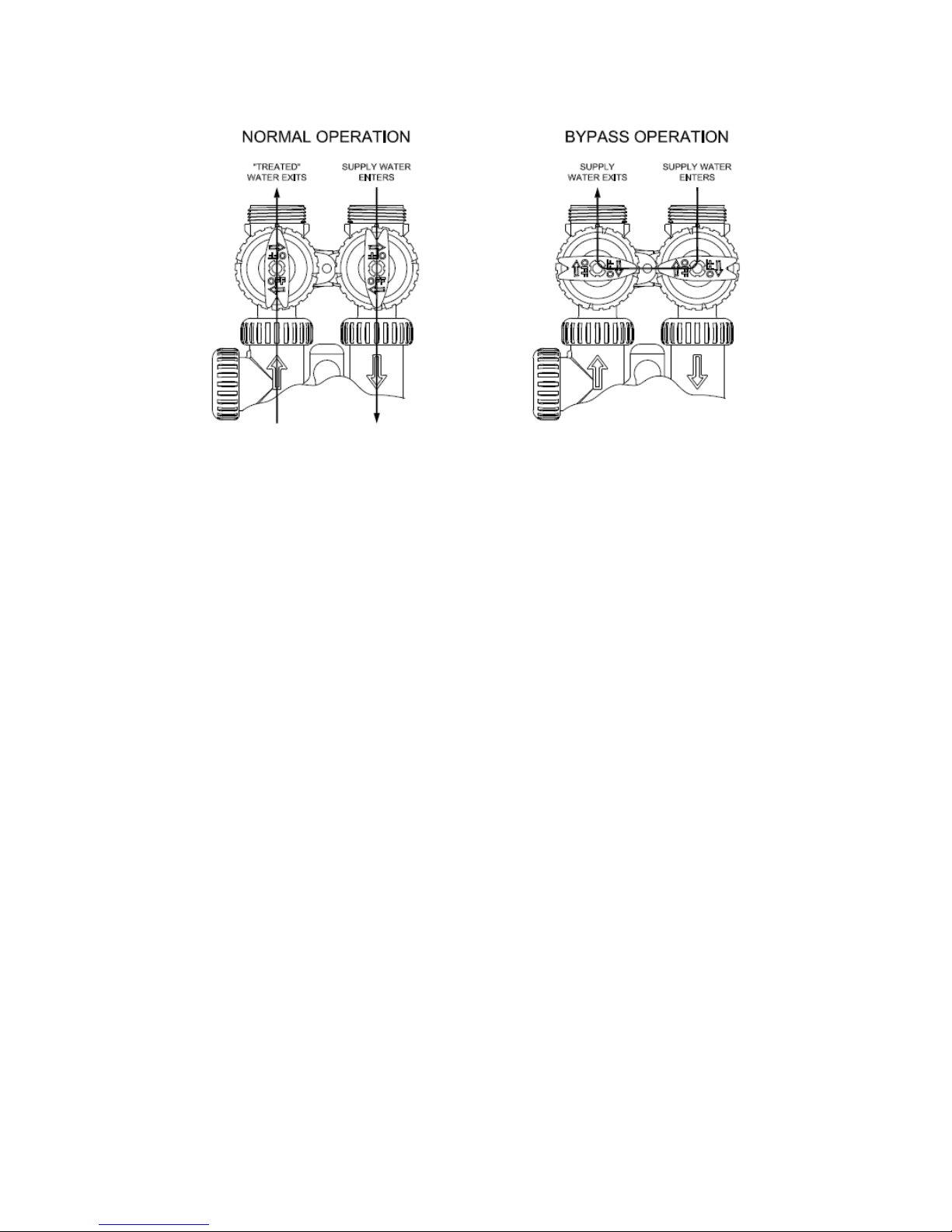
2. Connect water piping. This unit has been supplied with a manually operated bypass device which ena-
bles the softener to be isolated from the water service lines for maintenance and service, and also to main-
tain the continuity of the water supply when the softener is disconnected. Separate bypass fittings from
valve before sweating any copper. Overheating may cause damage to valve. Turn supplied bypass valve to
“Bypass” position (see Bypass Valve Diagram) and make connections to household water lines. Ensure
that inlet and outlet are properly piped, per arrows on valve body. Leave unit in “Bypass” position until
startup procedure.
3. Connect drain line. Remove barbed drain line fitting from parts bag. Apply Teflon tape to threads, and turn
into the female threaded opening on the back side of the control valve. Connect 5/8” drain line (supplied in
parts bag) to barbed end of drain line fitting and run to a nearby drain. Be sure not to submerse drain line
end into drain, as a 1 1/2” minimum air gap must be maintained to prevent potential backflow hazard. Firm-
ly secure at drain, while maintaining a minimum 1 1/2” air gap.
4. Connect brine line (two-tank models only). Connect 3/8” brine line (supplied in parts bag) to fitting on
brine tank and on the control valve. Tighten both fittings with an adjustable wrench.
5. Install brine tank overflow line. Install overflow fitting (supplied in parts bag) into hole in side of brine
tank. An owner-supplied overflow line should then be attached and run to a nearby drain. Failure to run
overflow line could cause flooding and water damage should the brine tank overflow.
6. Connect to electrical power source. Connect power cord to a dedicated 120v, 15 amp, ground fault inter-
rupt (GFI) outlet.
Proceed to start-up procedure.
Note: This system is not intended to be used for treating water that is microbiologically unsafe or of unknown
quality without disinfection before or after the system.
Bypass Valve Diagram
4
Start-Up Procedure
1. Set Time of Day
The user can also set the time of day. Time of day should only need to be set after
power outages lasting more than 8 hours, if the battery has been depleted and a pow-
er outage occurs, or when daylight saving time begins or ends. If a power outage last-
ing more than 8 hours occurs, the time of day will flash on and off which indicates the
time of day should be reset. If a power outage lasts less than 8 hours and the time of
day flashes on and off, the time of day should be reset and the battery replaced.
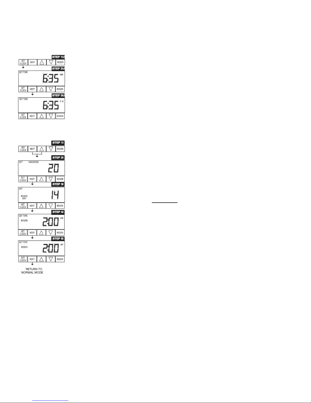
STEP 1U – Press SET CLOCK.
STEP 2U - Current Time (hour): Set the hour of the day using ▼or ▲buttons. AM/PM
toggles after 12. Press NEXT to go to step 3U.
STEP 3U - Current Time (minutes): Set the minutes of the day using ▼or ▲buttons.
Press NEXT to exit Set Clock. Press REGEN to return to previous step 2.
2. Program the System
STEP 1I - Press NEXT and ▲simultaneously for 3 seconds.
STEP 2I – Hardness: Set the amount of hardness in grains of hardness as calcium
carbonate per gallon using the ▼or ▲buttons. The default is 20 with value ranges
from 1 to 150 in 1 grain increments. Note: The grains per gallon can be in creased if
soluble iron needs to be reduced. Press NEXT to go to step 3I. Press REGEN to exit
Installer Display Settings.
STEP 3I – Day Override: When gallon capacity is set to off, Day Override sets the
number of days between regenerations. When gallon capacity is set to AUTO or to a
number, Day Override sets the maximum number of days between regenerations. If
value set to “oFF” regeneration initiation is based solely on gallons used. If value is set
as a number (allowable range from 1 to 28) a regeneration initiation will be called for
on that day even if sufficient number of gallons were not used to call for a regenera-
tion. Set Day Override using ▼or ▲buttons:
• number of days between regeneration (1 to 28); or
• “oFF”.
Press NEXT to go to step 4I. Press REGEN to return to previous step.
STEP 4I – Next Regeneration Time (hour): Set the hour of day for regeneration using
▼or ▲buttons. AM/PM toggles after 12. The default time is 2:00 a.m. Press NEXT to
go to step 5I. Press REGEN to return to previous step.
STEP 5I – Next Regeneration Time (minutes): Set the minutes of day for regeneration
using ▼or ▲buttons. Press NEXT to exit Installer Display Settings. Press REGEN to
return to previous step.
3. Fill the mineral tank with water: Slowly open bypass valve (see Bypass Valve Diagram, page 3).
Press and hold “REGEN” button until “RINSE” appears on the LCD screen. Allow water to flow until tank
is full and all air has been bled from the system, water will flow to the drain line. Allow water to flow for 3-
4 minutes.
4. Filling the brine tank with water: Slowly press “REGEN” 4 more times, waiting for the valve motor to
cycle on and off each time you press. “FILL” will appear on LCD screen. Water will begin to flow to the
brine tank. Allow control to fully complete this cycle. Once complete, the unit will go into regular service
and the time of day or gallons remaining will appear on LCD screen. This procedure will place the appro-
priate initial water fill in the brine tank.
System setup is now complete. Add salt to brine tank (Water Control recommends Morton System
Saver® pellets). Enjoy your soft water!
5
General Operation
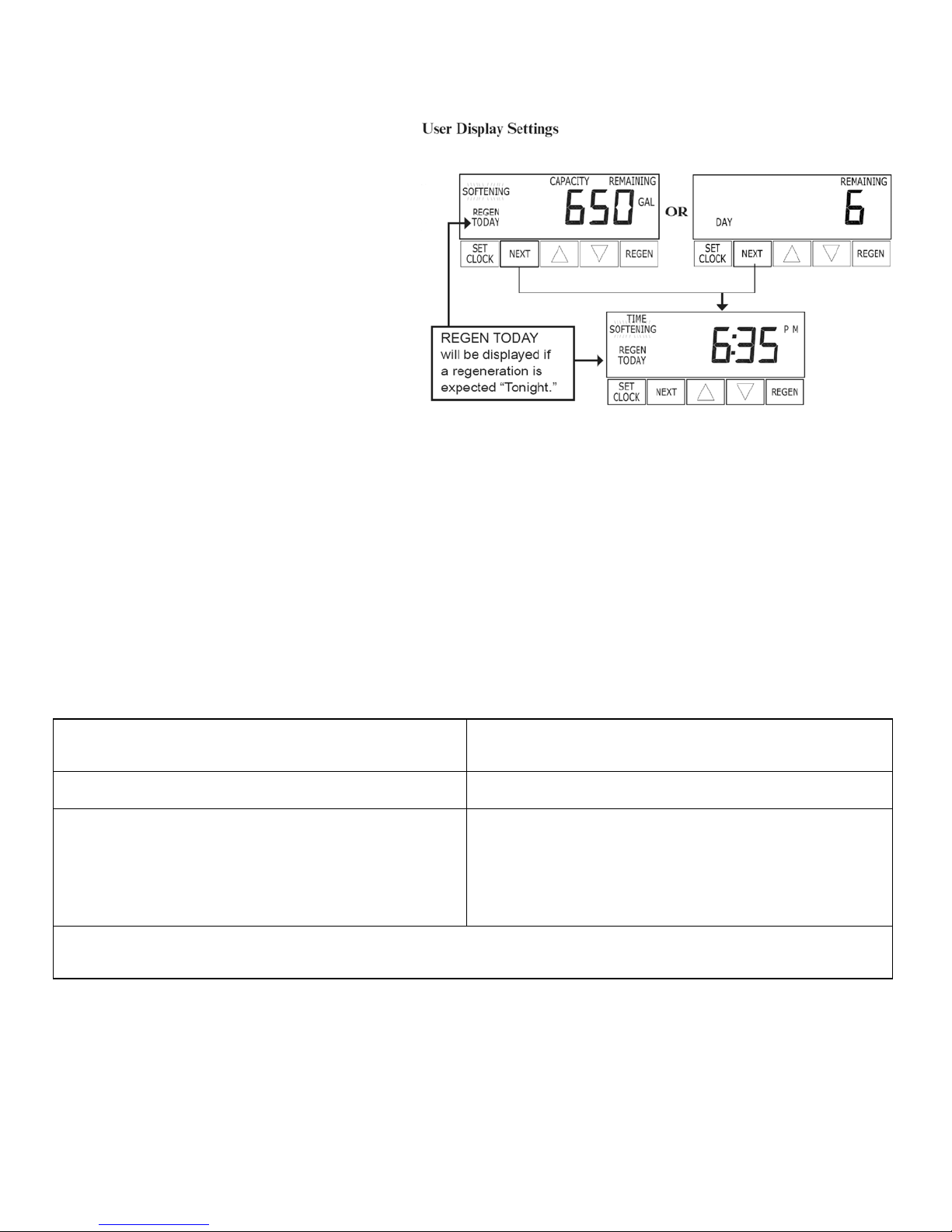
When the system is operating one of two
displays will be shown. Pressing NEXT will
alternate between the displays. One of the
displays is always the current time of day.
The second display is one of the following:
days remaining or gallons remaining. Days
remaining is the number of days left before
the system goes through a regeneration cy-
cle. Capacity remaining is the number of gal-
lons that will be treated before the system
goes through a regeneration cycle. The user
can scroll between the displays as desired.
If the system has called for a regeneration
that will occur at the preset time of regenera-
tion, the words “REGEN TODAY” will appear
on the display.
When water is being treated (i.e. water is flowing through the system) the word “Softening” or “Filtering”
flashes on the display if a water meter is installed.
Manual RegeneraƟon
To initiate a manual regeneration at the preset delayed regeneration time, press and release “REGEN”. The
words “REGEN TODAY” will flash on the display to indicate that the system will regenerate at the preset
delayed regeneration time. If you pressed the “REGEN” button in error, pressing the button again will cancel
the request.
To initiate a manual regeneration immediately, press and hold the “REGEN” button for three seconds. The
system will begin to regenerate immediately. The request cannot be cancelled.
SpecificaƟons
Minimum/Maximum Operating Pressures 20 psi (138 kPa or 1.4 bar) -
125 psi (862 kPa or 8.6 bar)
Minimum/Maximum Operating Temperatures 40°F (4°C) - 110°F (43°C)
Power Adapter:
Supply Voltage
Supply Frequency
Output Voltage
Output Current
120 V AC
60 Hz
12 V AC
500 mA
No user serviceable parts are on the PC board, the motor, or the power adapter. The means of
disconnection from the main power supply is by unplugging the power adapter from the wall.

6
General Warnings
The control valve, fittings and/or bypass are designed to accommodate minor plumbing misalignments but are not designed to sup-
port the weight of a system or the plumbing.
Do not use Vaseline, oils, other hydrocarbon lubricants or spray silicone anywhere. A silicone lubricant may be used on black o-
rings but is not necessary. Avoid any type of lubricants, including silicone, on the clear lip seals.
The nuts and caps are designed to be unscrewed or tightened by hand or with the special plastic wrench. If necessary a pliers can
be used to unscrew the nut or cap. Do not use a pipe wrench to tighten or loosen nuts or caps. Do not place a screwdriver in the
slots on caps and/or tap with a hammer.
Do not use pipe dope or other sealants on threads. Use Teflon tape on the threaded inlet, outlet and drain fittings. Teflon tape is not
necessary on the nut connection or caps because of o-ring seals.
After completing any valve maintenance involving the drive assembly or the drive cap assembly and pistons, unplug power source
jack from the printed circuit board (black wire) and plug back in or:
For valves that use a TC circuit board (three buttons) press and hold SET and DOWN buttons for 3 seconds. The cover button
may have other names like “SET HOUR”, “CLOCK” or “SET CLOCK” but the circuit board is labeled with SET.
For all other valves press and hold NEXT and REGEN buttons for 3 seconds.
This resets the electronics and establishes the service piston position. The display should flash all wording, then flash the software
version, and then reset the valve to the service position.
All plumbing should be done in accordance with local plumbing codes. The pipe size for the drain line should be a minimum of ½”.
Backwash flow rates in excess of 7 gpm (26.5 lpm) or length in excess of 20’ (6.1m) require ¾” drain line.
Solder joints near the drain must be done prior to connecting the drain line flow control fitting. Leave at least 6” between the drain
line control fitting and solder joints when soldering pipes that are connected on the drain line control fitting. Failure to do this could
cause interior damage to the drain line flow control fitting.
When assembling the installation fitting package (inlet and outlet), connect the fitting to the plumbing system first and then attach
the nut, split ring and o-ring. Heat from soldering or solvent cements may damage the nut, split ring, or o-ring. Solder joints should
be cool and solvent cements should be set before installing the nut, split ring, and o-ring. Avoid getting primer and solvent cement
on any part of the o-rings, split rings, bypass valve, or control valve.
Plug into an electrical outlet. Note: All electrical connections must be connected according to local codes. (Be certain the outlet is
uninterrupted.)
Install grounding strap on metal pipes.
Control Valve Function and Cycles of Operation
This glass filled Noryl (or equivalent) fully automatic control valve is designed as the primary control center to direct and regulate all
cycles of a water softener or filter. When the WS1 control valve is manufactured as a softener, the control valve can be ordered to
perform downflow or upflow regeneration. The WS1.25 control valve is only available in downflow regeneration. When the WS1 or
WS1.25 control valve is set up as a filter, the control valve can be set to perform downflow regeneration or simply backwash. The
control valve can be set to regenerate on demand (consumption of a predetermined amount of water) and/or as a time clock
(passage of a particular number of days). The control valve can be set so that a softener can meet the Water Quality Association
(WQA) Standard S100 or NSF/ANSI Standard 44 efficiency rating.
It is not recommended to change control valves from downflow to upflow brining or vice versa in the field. The valve bod-
ies for downflow and upflow are unique to the regeneration type and should not be interchanged. A mismatch of valve
body and regeneration piston will result in hard water bypass during service.
The control valve is compatible with a variety of regenerants and resin cleaners. The control valve is capable of routing the flow of
water in the necessary paths to regenerate or backwash water treatment systems. The injector regulates the flow of brine or other
regenerants. The control valve regulates the flow rates for backwashing, rinsing, and the replenishing of treated water into a regen-
erant tank, when applicable.
The control valve uses no traditional fasteners (e.g. screws); instead clips, threaded caps and nuts and snap type latches are used.
Caps and nuts only need to be firmly hand tightened because radial seals are used. Tools required to service the valve include one
small blade screw driver, one large blade screw driver, pliers, and a pair of hands. A plastic wrench is available which eliminates the
need for screwdrivers and pliers. Disassembly for servicing takes much less time than comparable products currently on the market.
Control valve installation is made easy because the distributor tube can be cut ½” above to ½” below the top of tank thread. The
distributor tube is held in place by an o-ring seal and the control valve also has a bayonet lock feature for upper distributor baskets.
The AC adapter power pack comes with a 15 foot power cord and is designed for use with the control valve. The AC adapter power
pack is for dry location use only. The control valve remembers all settings until the battery power is depleted if the power goes out.
After the battery power is depleted, the only item that needs to be reset is the time of day; other values are permanently stored in
the nonvolatile memory. The control valve battery is not rechargeable but is replaceable.
7
Official Warranty
Water Control Corporation
Dakotah Series Water Softeners
Limited Warranty
Water Control Corporation warrants the control valve to be free of manufacturers defects for a period of 3 (three)
years from the date of installation, and the fiberglass reinforced mineral tank, and plastic brine tank, to be free from
leaking due to manufacturer’s defects for a period of 5 (five) years. We will, at our discretion, repair or replace defec-
tive products. This warranty does not include any costs associated with removal of defective products, or installation
of replacement products. All replacement parts will be provided FOB Ramsey, MN. This warranty is transferable.
DISCLAIMER OF IMPLIED WARRANTIES
Water Control Corporation makes no warranties except those expressly stated in this document. To the extent permit-
ted by the laws of the applicable state, ALL WARRANTIES CONTAINED IN THIS DOCUMENT ARE EX-
PRESSLY IN LIEU OF, AND WATER CONTROL CORPORATION EXPRESSLY DISCLAIMS, ANY AND
ALL OTHER WARRANTIES, EXPRESS OR IMPLIED, INCLUDING THE WARRANTIES OF MER-
CHANTABILITY AND FITNESS FOR A PARTICULAR PURPOSE.
WHAT IS NOT COVERED BY THESE WARRANTIES
1. Conditions and damages resulting from any of the following:
- Wear caused by unfavorable water conditions
- Improper installation, delivery, or maintenance
- Any repair, modification, alteration, or adjustment not authorized
by the manufacturer or an authorized servicer
- Misuse, abuse, accidents, or unreasonable use
- Improper setting of any control
- Incorrect electric current, voltage, or supply
2. Warranties are void if the original serial numbers have been removed, altered, or cannot be readily determined.
3. The cost of service or service call to:
- Correct installation errors
- Instruct the user on proper use of the product
- Transport the product to the servicer
4. Any costs associated with removal of defective products, or installation of replacement products.
5. Consequential, special, or incidental damages sustained by any person as a result of the breach of these
warranties. Some states do not allow the exclusion or limitation of consequential or incidental damages,
so the above exclusion may not apply to you.

8
WaterControlCorporation
7150143rdAveNW●Ramsey,MN55303
Phone:1‐866‐405‐1268●Fax:763‐427‐5665
www.watercontrolinc.com
Table of contents
Other Water Control Water Dispenser manuals


Popular Water Dispenser manuals by other brands


Aqua To Go
Aqua To Go Argento Cleaning instructions

Primo Water
Primo Water 900172 user manual

DS Services of America
DS Services of America 200K Series How to Clean

H2O International
H2O International H2O 1000 Operation manual

North Star
North Star NST30ED Installation and operation manual

Spectra Watermakers
Spectra Watermakers Z-Ion Catalina 300 Mk II installation instructions


