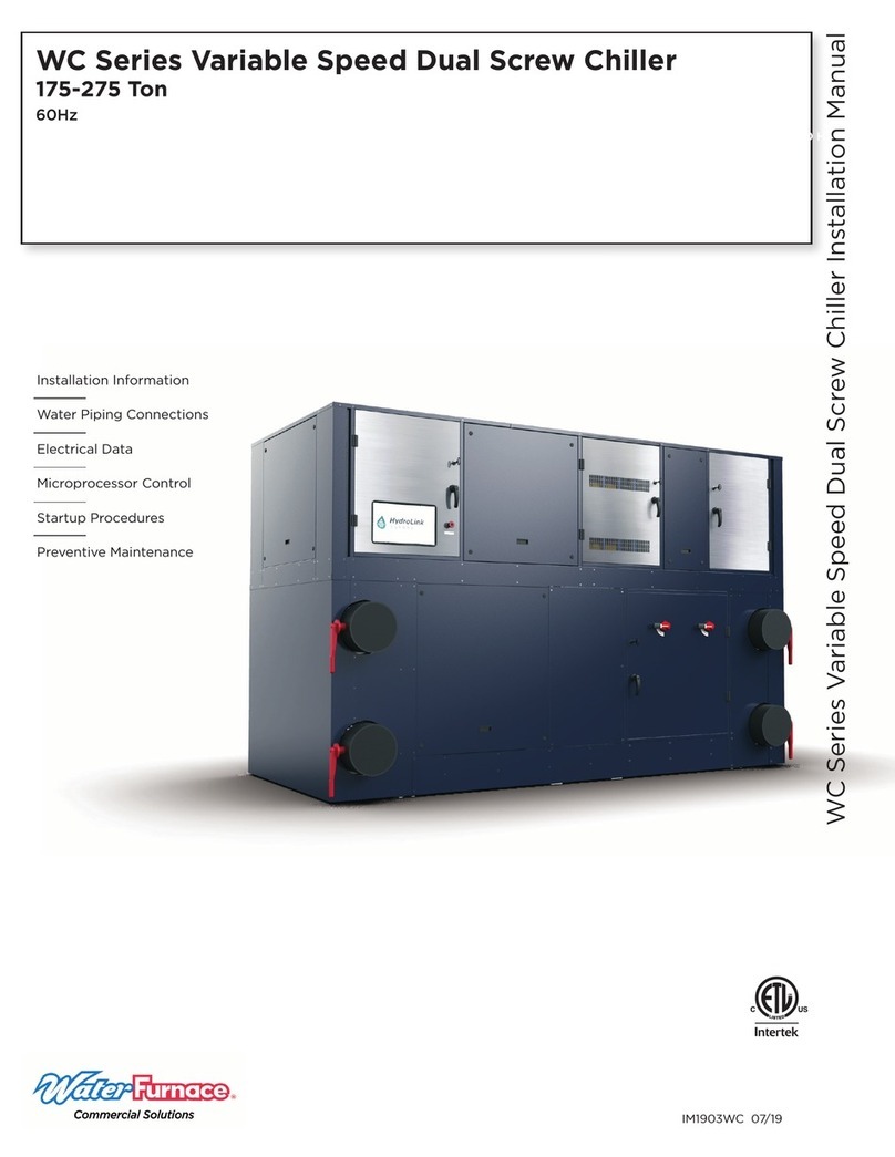
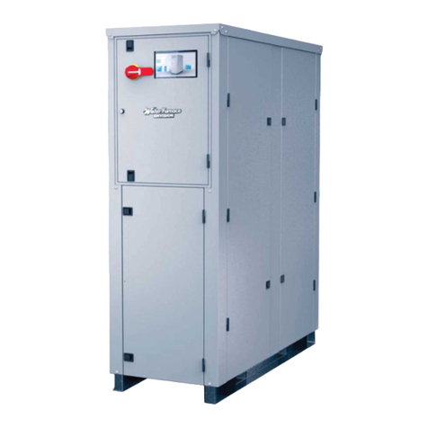
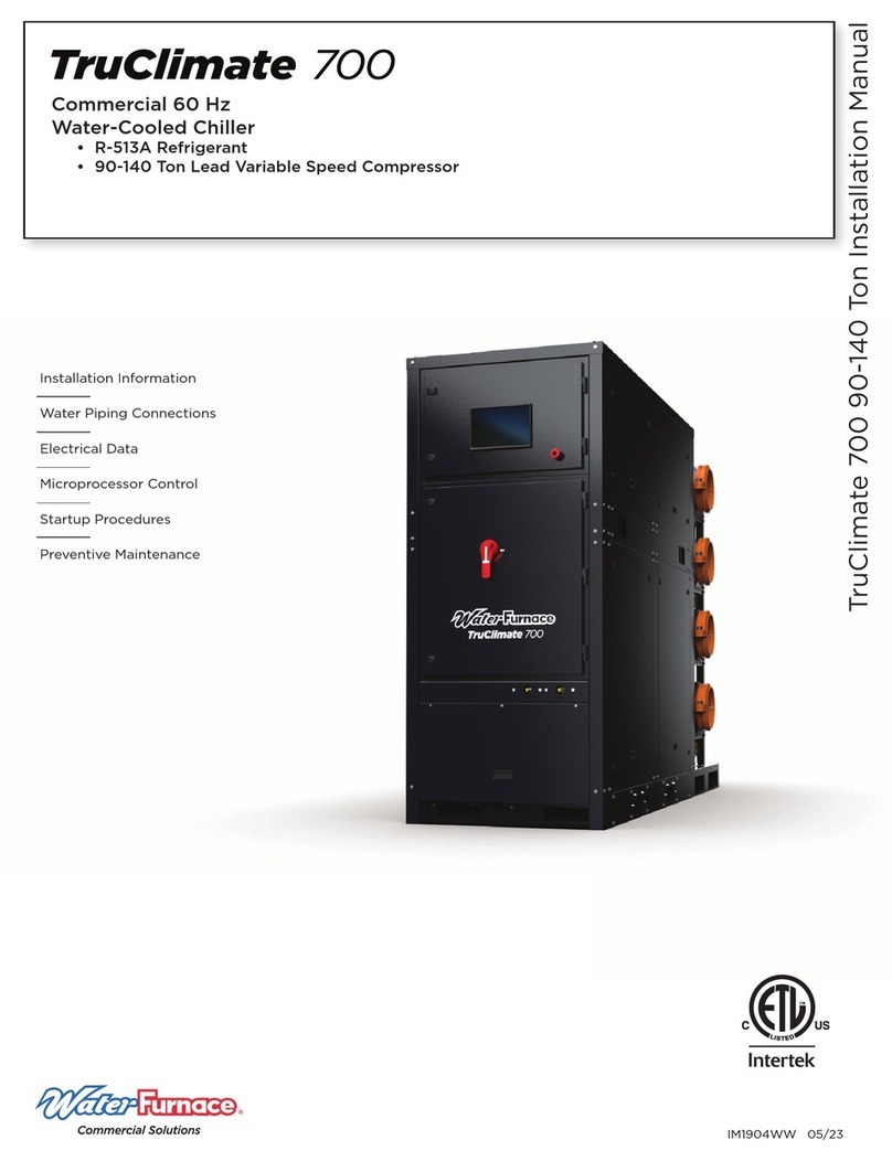
Water Furnace TruClimate 300 User manual

IM1910WW 01/22
Installation Information
Water Piping Connections
Electrical Data
Microprocessor Control
Startup Procedures
Preventive Maintenance
TruClimate 300 Water-Cooled Chiller with HybrEx Technology Installation Manual
ll l
Formerly WC HybrEx Chiller
Commercial 60 Hz
Water-Cooled Chiller with HybrEx Technology
• R-410A Refrigerant
• 30-50 Tons


TRUCLIMATE 300 WATER-COOLED CHILLER WITH HYBREX TECHNOLOGY INSTALLATION MANUAL - Formerly the WC Hybrex Chiller
Table of Contents
General Installation Information . . . . . . . . . . . . . . . . . . . . . . . . . . . . . . . . . . . . . . . . . . . . . . . . . . . . 4
Nomenclature . . . . . . . . . . . . . . . . . . . . . . . . . . . . . . . . . . . . . . . . . . . . . . . . . . . . . . . . . . . . . . . . . . . . 5
Unit and Accessory Nameplates . . . . . . . . . . . . . . . . . . . . . . . . . . . . . . . . . . . . . . . . . . . . . . . . . . . . 8
The WC HybrEx Chiller . . . . . . . . . . . . . . . . . . . . . . . . . . . . . . . . . . . . . . . . . . . . . . . . . . . . . . . . . . . . 9
The WC HybrEx Chiller Features . . . . . . . . . . . . . . . . . . . . . . . . . . . . . . . . . . . . . . . . . . . . . . . . . . . 10
Physical Data . . . . . . . . . . . . . . . . . . . . . . . . . . . . . . . . . . . . . . . . . . . . . . . . . . . . . . . . . . . . . . . . . . . . 13
Electrical Data, Voltage Availability, Compressor Resistance . . . . . . . . . . . . . . . . . . . . . . . . . . 14
Dimensional Data . . . . . . . . . . . . . . . . . . . . . . . . . . . . . . . . . . . . . . . . . . . . . . . . . . . . . . . . . . . . . . . . 15
Pressure Drop . . . . . . . . . . . . . . . . . . . . . . . . . . . . . . . . . . . . . . . . . . . . . . . . . . . . . . . . . . . . . . . . . . . 23
Operating Limits . . . . . . . . . . . . . . . . . . . . . . . . . . . . . . . . . . . . . . . . . . . . . . . . . . . . . . . . . . . . . . . . . 25
Leaving Water Temperature Operational Maps . . . . . . . . . . . . . . . . . . . . . . . . . . . . . . . . . . . . . .26
HPC and MOP Entering Water Temperature Limits . . . . . . . . . . . . . . . . . . . . . . . . . . . . . . . . . . . 27
Chiller Components . . . . . . . . . . . . . . . . . . . . . . . . . . . . . . . . . . . . . . . . . . . . . . . . . . . . . . . . . . . . . .28
Detailed Component Callouts . . . . . . . . . . . . . . . . . . . . . . . . . . . . . . . . . . . . . . . . . . . . . . . . . . . . .29
Electrical System and Controls . . . . . . . . . . . . . . . . . . . . . . . . . . . . . . . . . . . . . . . . . . . . . . . . . . . . 31
Aurora HydroLink2 Chiller Control System . . . . . . . . . . . . . . . . . . . . . . . . . . . . . . . . . . . . . . . . . . 33
Wiring Schematics . . . . . . . . . . . . . . . . . . . . . . . . . . . . . . . . . . . . . . . . . . . . . . . . . . . . . . . . . . . . . . 40
Single Point Disconnect Panel Accessories. . . . . . . . . . . . . . . . . . . . . . . . . . . . . . . . . . . . . . . . . .46
Refrigerant and Water Circuit Overview . . . . . . . . . . . . . . . . . . . . . . . . . . . . . . . . . . . . . . . . . . . .47
Application Requirements . . . . . . . . . . . . . . . . . . . . . . . . . . . . . . . . . . . . . . . . . . . . . . . . . . . . . . . . 51
Chiller Installation . . . . . . . . . . . . . . . . . . . . . . . . . . . . . . . . . . . . . . . . . . . . . . . . . . . . . . . . . . . . . . . . 52
Chiller Plant with Single Point Disconnect Panel . . . . . . . . . . . . . . . . . . . . . . . . . . . . . . . . . . . . .58
Chiller Plant Controls Wiring . . . . . . . . . . . . . . . . . . . . . . . . . . . . . . . . . . . . . . . . . . . . . . . . . . . . . 60
Operation & Connection, Reference Calculations, Legend and Chiller Plant Startup
. . . . . . . . 61
Scroll Refrigeration Cycle Analysis . . . . . . . . . . . . . . . . . . . . . . . . . . . . . . . . . . . . . . . . . . . . . . . . .63
Chiller Maintenance . . . . . . . . . . . . . . . . . . . . . . . . . . . . . . . . . . . . . . . . . . . . . . . . . . . . . . . . . . . . . .64
Troubleshooting Form . . . . . . . . . . . . . . . . . . . . . . . . . . . . . . . . . . . . . . . . . . . . . . . . . . . . . . . . . . . .65

4
TRUCLIMATE 300 WATER-COOLED CHILLER WITH HYBREX TECHNOLOGY INSTALLATION MANUAL - Formerly the WC Hybrex Chiller
Safety Considerations
Installing and servicing air conditioning and heating
equipment can be hazardous due to system pressure and
electrical components. Only trained and qualified service
personnel should install, repair or service heating and air
conditioning equipment. When working on heating and
air conditioning equipment, observe precautions in the
literature, tags and labels attached to the unit and other
safety precautions that may apply.
Follow all safety codes. Wear safety glasses and work
gloves. Use quenching cloth for brazing operations. Have
fire extinguisher available for all brazing operations.
NOTE: Before installing, check voltage of unit(s) to ensure
proper voltage.
WARNING: Before performing service or
maintenance operations on the system, turn off
main power switches to the unit. Electrical shock
could cause serious personal injury.
Moving and Storage
Move units in the normal “Up” orientation as indicated by
the labels on the unit packaging. When the equipment
is received, all items should be carefully checked against
the bill of lading to ensure that all crates and cartons
have been received in good condition. Examine units for
shipping damage, removing unit packaging if necessary
to properly inspect unit. Units in question should also
be internally inspected. If any damage is observed, the
carrier should make the proper notation on delivery receipt
acknowledging the damage. Units are to be stored in a
location that provides adequate protection from dirt, debris
and moisture.
Units are setup to be side picked using a fork lift. Some
units include pick bars allowing for picking from the end
with required fork lengths. Note unit labels and markings
for safe picking points. Do not pick the unit up from points
not specified and keep the unit level during transport and
handling. Using improper equipment handling methods can
result in damage and/or void the warranty.
WARNING: To avoid equipment damage, do not
leave the system filled in a building without heat
during cold weather, unless adequate freeze
protection levels of antifreeze are used. Heat
exchangers do not fully drain and will freeze
unless protected, causing permanent damage.
General Installation Information
Unit Location
Provide sufficient room to make water and electrical
connections. If the unit is located in a confined space,
provisions must be made for unit servicing. Locate the
unit in an indoor area that allows easy removal of the
access panels and has enough space for service personnel
to perform maintenance or repair. These units are not
approved for outdoor installation and, therefore, must be
installed inside the structure being conditioned. Do not
locate units in areas subject to freezing conditions.
WARNING: Do not store or install units in
corrosive environments or in locations subject
to temperature or humidity extremes (e.g. attics,
garages, rooftops, etc.). Corrosive conditions and
high temperature or humidity can significantly
reduce performance, reliability, and service life.
WARNING: To avoid equipment damage and
possible voiding of warranty, be sure that
properly sized strainers are installed upstream
of both brazed plate heat exchangers to protect
them against particles in the fluid.

5
TRUCLIMATE 300 WATER-COOLED CHILLER WITH HYBREX TECHNOLOGY INSTALLATION MANUAL - Formerly the WC Hybrex Chiller
Model Nomenclature
All WCX Series product is Safety listed under UL1995 thru ETL.
WaterFurnace’s TruClimate WCH/WCX products are certified by AHRI
to AHRI Standard 550/590 for Water-Cooled Water Chilling and Heat
Pump Water-Heating Packages.
WCX D M 030 * 3 A
Brand
W –WaterFurnace
Model Type
CX –Coax Chiller Cooling Only
Compressor Type
D –Dual Scroll
V –Variable Speed Lead Scroll
Cabinet Configuration
M –Modular
Unit Capacity (Nominal Tons)
030 , 050
Vintage
* – Factory Use Only
Voltage
3 – 208-230/60/3
4 – 460/60/3
Electrical Option
A –Non-Fused Disconnect
C –Fused Disconnect
D –Power Distribution Block (no disconnect)
Control Option1
A –Secondary Unit
B –Secondary Unit (Left Single Point Disconnect Panel)
C –Secondary Unit (Right Single Point Disconnect Panel)
D –Primary Unit (Master Controller)
X –Primary Unit (Master Controller and Left Single Point Disconnect Panel)
W –Primary Unit (Master Controller and Right Single Point Disconnect Panel)
Sound Kit Option
A –None
B –Compressor Sound Blanket
Cabinet Option
S –Standard
Non-Standard Options
SSS –None
Future Option
N –Not Applicable
Future Option
0 – Not Applicable
Unit Designator
1 – Unit 1 Primary Unit Only
2 – Unit 2 Secondary Unit Only
3 – Unit 3 Secondary Unit Only
4 – Unit 4 Secondary Unit Only
5 – Unit 5 Secondary Unit Only
6 – Unit 6 Secondary Unit Only
7 – Unit 7 Secondary Unit Only
8 – Unit 8 Secondary Unit Only
9 – Unit 9 Secondary Unit Only
A –Unit 10 Secondary Unit Only
B –Unit 11 Secondary Unit Only
c –Unit 12 Secondary Unit Only
Coax Condenser Option
1 – No strainer
2 – Strainer
Water Control Option
6GC –Grooved 6in integrated 4
pipe
Evaporator Option
N –No Strainer
S –Standard (Strainer)
Refrigeration Option
3 – EEV
A B S 3
WCXDM030A3AABS3S6GC100NSSS
N
Notes:
1. Primary unit selection is required for multiple unit staging control. Left and Right
Configurations refers to placement of the single point breaker panel.
SSS6GC
2-3 5 6-8 10 11 12 13 15
14 16 17 - 19 20 21 22 23 24-2691 4
1 0 0 N
Table of contents
Other Water Furnace Chiller manuals
Popular Chiller manuals by other brands
Trane
Trane RTAA-70 Installation & maintenance guide
Carrier
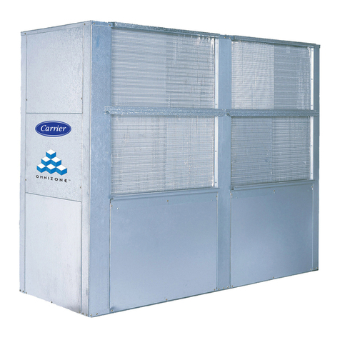
Carrier Omnizone 50BVC Installation, Start-Up, Service and Controls Operation and Troubleshooting

York
York YGWH 115 Installation, commissioning & operation

Galletti
Galletti PERFORMA MPE Series Technical manual

SMC Networks
SMC Networks HRR Series manual

Daikin
Daikin EWAQ016CAW Installation and operation manual
