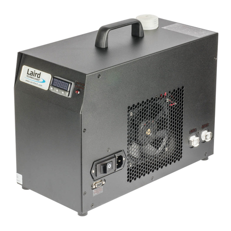
Laird OW 4002 User manual

Manual OW 4002
Laird Technologies GmbH OW 4002 page 1/10
1155.00be May 2013
Caution:
♦Warning: This manual should be fully read and understood be-
fore starting installation!
♦Power supply 230 V 50/60 Hz!
♦Run cooling unit always with correct oil level otherwise damage
of pump may occur!
♦Never operate damaged or leaking equipment!
♦Before starting any service work disconnect the cooling unit
from the power source!
Laird Technologies GmbH
Borsigstraße 1
D-24568 Kaltenkrichen
Phone: +49(0)4191-999 30
Fax: +49(0)4191-999 333
Email: info-lcs@Lairdtech.com
Homepage: www.Lairdtech.com

Manual OW 4002
Laird Technologies GmbH OW 4002 page 2/10
1155.00be May 2013
Table of contents Page
1. Description ........................................................................................................................ 2
2. Technical data................................................................................................................... 3
2.1 Physical dimensions ................................................................................................... 3
2.2 Performance data ....................................................................................................... 3
2.3 Environment specifications ......................................................................................... 3
2.4 Settings....................................................................................................................... 3
3. Setting to work .................................................................................................................. 4
4. Maintenance...................................................................................................................... 4
5. Putting out of operation. .................................................................................................... 4
6. Spare part list and illustrations .......................................................................................... 5
7. Cooling performance ......................................................................................................... 7
8. Flow Chart and Circiute Diagram....................................................................................... 8
9. Declaration of Conformity.................................................................................................10
1. Description
The cooling unit OW 4002 is intended for the cooling of an oil circuit. Oil circulates between
the cooling unit and the heat source. The oil is re-cooled by a water-cooled heat exchanger.
Cooling hoses are connected to the cooling unit via screw and via hose nipples.
Coolant inlet and outlet are marked with symbols: Inlet:
O
↓
, outlet
O
↑
The oil flow is monitored by an adjustable flow switch, the oil temperature by an adjustable
thermal switch. The signals of the flow switch and the thermal switch are available at a po-
tential free safety circuit. The oil pressure is limited by an adjustable bypass valve.
The capacity of the cooling unit depends on the temperature difference between the cooling
water temperature and the oil outlet temperature.
You can take it from diagram on page 7
Inlet:
O
↓
outlet:
O
↑

Manual OW 4002
Laird Technologies GmbH OW 4002 page 3/10
1155.00be May 2013
2. Technical data
2.1 Physical dimensions
Length: 621 mm
Width: 350 mm
Height: 551 mm
Weight: ca. 45 kg without oil
Fuel capacity oil: app. 23 l
2.2 Performance data
Cooling capacity: 4000 W,
Oil flow: > 17 l/min at 3,5 bar related to oil temperature 22°C ± 3°C
Voltage rating: 230V ± 10% / 50/60 Hz
Current consumption : 3,6 A by 6 bar
Noise level: 60 dB (A) (50 Hz) distance 1 m in any direction
2.3 Environment specifications
Ambient temperature: +5°C...+40°C
Storage temperature: -40°C...+70°C without coolant
Air humidity: 20%...80%
2.4 Settings
System pressure: 9,0 bar
Flow switch: 17,0 l/min
Temp. controller (on) 55°C

Manual OW 4002
Laird Technologies GmbH OW 4002 page 4/10
1155.00be May 2013
3. Setting to work
Remove cover
Remove cap of oil reservoir and fill with oil up to the visible mark
Connect oil hoses to cooler.
Connect water supply to cooler.
Establish electrical connections according wiring diagram, use suitable leads.
Start water supply to cooler.
Start power supply for cooler
Exhaust valve open
Run oil cooler for approximately 10 minutes to
remove air from the oil circuit.
Exhaust valve close
Check oil level and refill if necessary
Stop cooling unit
Close cap of oil reservoir.
Mount cover.
Cooling unit is ready for use.
4. Maintenance
Check oil level at inspection glass monthly or more often, if necessary and refill oil.
5. Putting out of operation.
- Stop oil circulation by switching off pump.
- Disconnect equipment from mains.
- Lock oil supply and return pipes.
- Lock cooling water supply and return pipes.
- Drain water off the cooling system for frost.
Inspection glass

Manual OW 4002
Laird Technologies GmbH OW 4002 page 5/10
1155.00be May 2013
6. Spare part list and illustrations
No. Description Code number
1 engine pump unit KA-1-26-230-2 95205237.00
2 motor capacitor 95290735.00
3 safety valve Type 618 T 96121014.00
4 flow controller FW1 95140572.00
5 switch head 95140567.00
6 temperature controller water 25-65°C 95100101.00
7 thermostat AMFS-13 95160001.00
8 strainer 125 µm 93314901.00
9 filler neck 95169901.00
10 inspection glass 93300201.00

Manual OW 4002
Laird Technologies GmbH OW 4002 page 6/10
1155.00be May 2013
1
8
10
5
4
6
3
2
9
7

Manual OW 4002
Laird Technologies GmbH OW 4002 page 7/10
1155.00be May 2013
7. Cooling performance
Cooling performance 4,0 kW, oil temperature vs. water temperature and flow rate
Tw = Temperature Water inlet
P1 = Pressure Water inlet
P2 = Pressure Water outlet
Pressure drop = P1- P2
Water
Oil
Tw, P1
P2
to x-ray tube
Rating 4,0kW

Connector distances


Kontakt
Bankverbindung
Geschäftsführer:
Telefon (0049) 4191 9993-0
Commerzbank Kaltenkirchen
Olaf Dany, Michael Michels,
Telefax (0049) 4191 9993-33
(BLZ 221 41028) 3740206
Kai Borchert
S.W.I.F.T.-BIC: COBA DE FF XXX
HRB 2320-BB
Internet: www.Lairdtech.com
IBAN: DE28 2214 1028 0374 0206 00
Amtsgericht Kiel
E-Mail: info-lcs@Lairdtech.com
Ust-IdNr. DE 134849216
St.-Nr. 11 293 00256
Laird Technologies GmbH Borsigstraße. 1 D- 24568 Kaltenkirchen
Konformitätserklärung
Declaration of Conformity
Wir: Laird Technologies GmbH
We: (Name des Hersteller / supplier’s name)
Borsigstrasse 1
24568 Kaltenkirchen
Deutschland / Germany
Erklären in alleiniger Verantwortung, dass das Produkt
Declare under our sole responsibility that the product
_____________________________________________________________________
Kühlaggregate
Cooling aggregate
Modelle / types WL, WLK, OL, OLK, OW, WW
_____________________________________________________________________
auf das sich die Erklärung bezieht / to which this declaration relates,
mit den folgenden Normen oder normativen Dokumenten übereinstimmt,
is in conformity with the following standards or normative documents
_____________________________________________________________________
DIN EN ISO 12100-1 (2004-04)
DIN EN ISO 12100-2 (2004-04)
DIN EN 60204-1 (2009-10)
DIN EN 349 (2009-09)
Gemäß den Bestimmungen der Richtlinie 2006/42/EG
Following the provisions of directive 2006/42/EEC
_____________________________________________________________________
Kaltenkirchen Leiter Qualitätsmanagement Lothar Lühr
2010-12-23 Leader Qualitymanagement
Ort / Datum / der Ausstellung Funktion Name / Unterschrift
Place / date of issue Responsibility Name/ signature
Table of contents
Other Laird Chiller manuals
Popular Chiller manuals by other brands

AERMEC
AERMEC WRL 200 installation manual

Daikin
Daikin WGZ030DW Installation and maintenance manual

Thermal Care
Thermal Care TSE Operation, installation, and maintenance manual

Lennox
Lennox GAH 020S Installation, operating and maintenance manual

Trane
Trane Airfinity XL IC140 manual

Randell
Randell BC-18-PUB Operator's manual

Hoshizaki
Hoshizaki Lancer Superchiller Remote R8E V2 Series Installation, operation & service manual

York
York YCRS Series Installation, operation and maintenance

Moffat
Moffat Friginox TSR-11A Specifications

Traulsen
Traulsen KROGER RBC50 Specifications

Studio 54
Studio 54 Alexander 2/3 Instructions for use

Modena
Modena CC 3180 User manual book