Water-Loo 750EFDMSDBK User manual

Dual Sensor
Water/Soap Dispenser
Installation Manual
750EFDMSDBK / 750EFDMSDC
To assure that the product
operates properly, please make
sure to follow all procedures
within this instruction manual.
Product Specs:
1. Operating Power: 6V / 2A
2. Operating Water Pressure: 10 to 100 PSI
3. Soap Dispensing Time: 0.5-2 seconds
(Factory setting is 2 seconds.)
4. Soap Reservoir Capacity: 1.5L
(Only use foaming soap)
5. Sensor Distance: 1¼-6 in.
(Factory setting is 4 in.)
6. Response Time: 0.2 seconds
7. Shut-Off Time: 1 seconds
8. Operating Temperature: 5-70°C / 41-158°F
rev. 08/23

Dual Sensor
Water/Soap Dispenser
Installation Manual
Faucet Body Component List
1.
2. 4.
5.
6.
13.
14.
7.
9.
10.
8.
3.
11.
12.
1. Spout Body
2. Faucet Sensor
3. Spout
4. Soap Sensor
5. Soap Spout
6. Base Gasket
7. Gasket
8. Fixation Washer
9. Fixation Nut
10. Tightening Screw
11. Outlet Hose
12. Soap Tube
13. Sensor Cable
for Soap (White)
14. Sensor Cable
for Faucet (Black)
Control Module Component List
18.
23.24.
25.
26.
16.
27.
17.
19.
20.
21.
22.
15.
35.
37.
34.
36.
15. Dial Cover
16. Outlet for Water
17. Soap Outlet
18. Sensor Connector
for Soap Dispenser
19. Sensor Connector
for Faucet
20. Soap Dispenser
Rest/Purge Button
21. Soap Dispenser
Setting DIP Switch
22. Faucet Reset/
Purge Button
23. Power Inlet for
AC Adapter
24. Inlet for Soap
(Black Tube)
25. Water Inlet
26. Fixation Tab
27. Filter
34. Mixing valve,
Hot and Cold Water Hoses
35. Rubber Washer
36. Black Tube
37. Clip Fastener

Dual Sensor
Water/Soap Dispenser
Installation Manual
Soap Canister Component List
33.
29.
28.
32.
31.
30.
28. Soap Outlet to
Control Module
29. Soap Canister Mount
30. Fixation Pin
31. Mount Holes
32. Re-filler Cap
33. Canister Fixation Hook
Installation Diagram
Please note that actual installation may differ based
on actual application.
Mixing Valve
Hot Water &
Cold Water Hose
Floor
Dual Sensor
Water/Soap Dispenser
Installation Manual
Installation Diagram
Installation Diagram
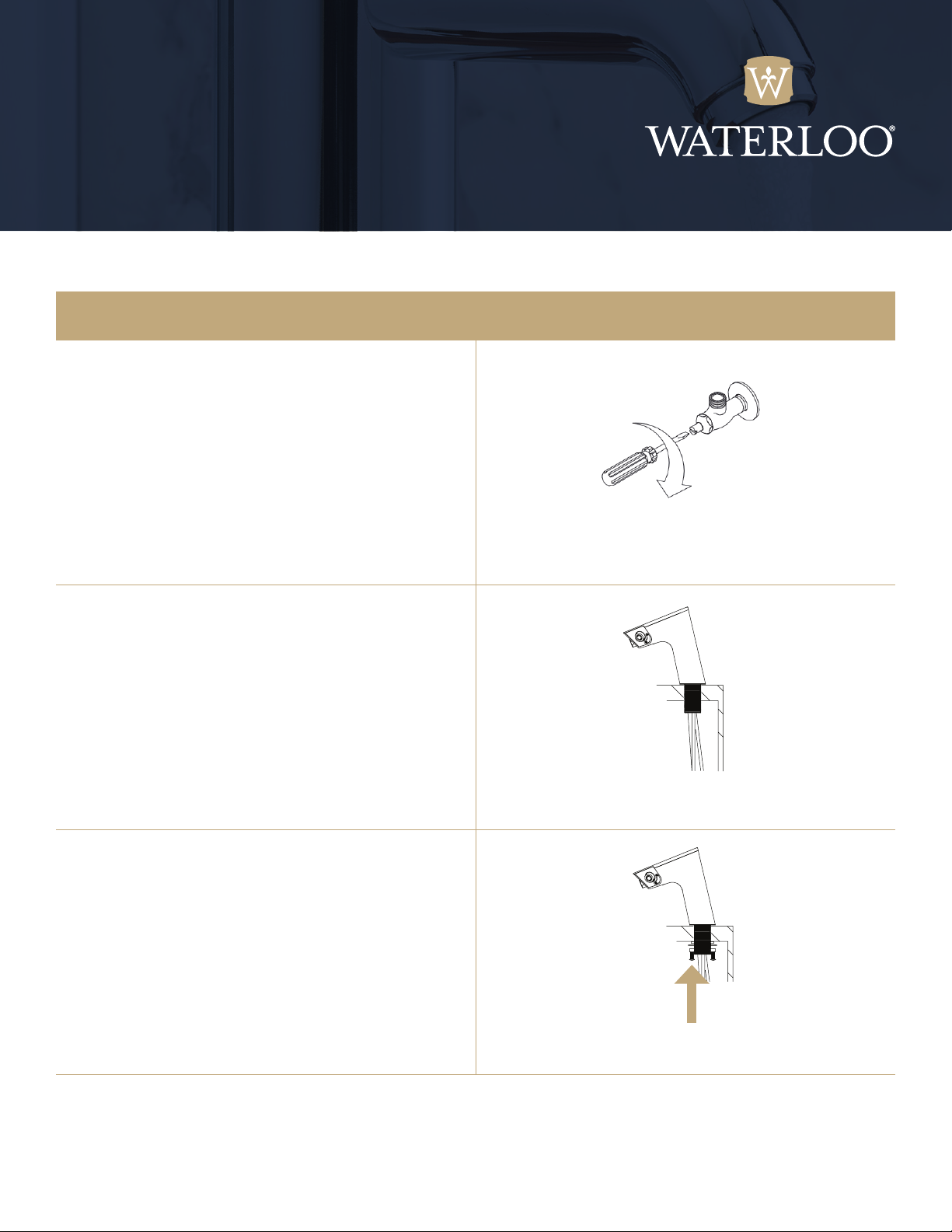
1. Shut off water valve.
2. Thread the wires and hoses through your counter
hole. Make sure spout body and base gasket are flat
on the counter.
3. Tightly secure the spout body by using the
fixation washer, gasket, nut and screw (7, 8, 9, 10).

Dual Sensor
Water/Soap Dispenser
Installation Manual
Installation Diagram
Installation Diagram
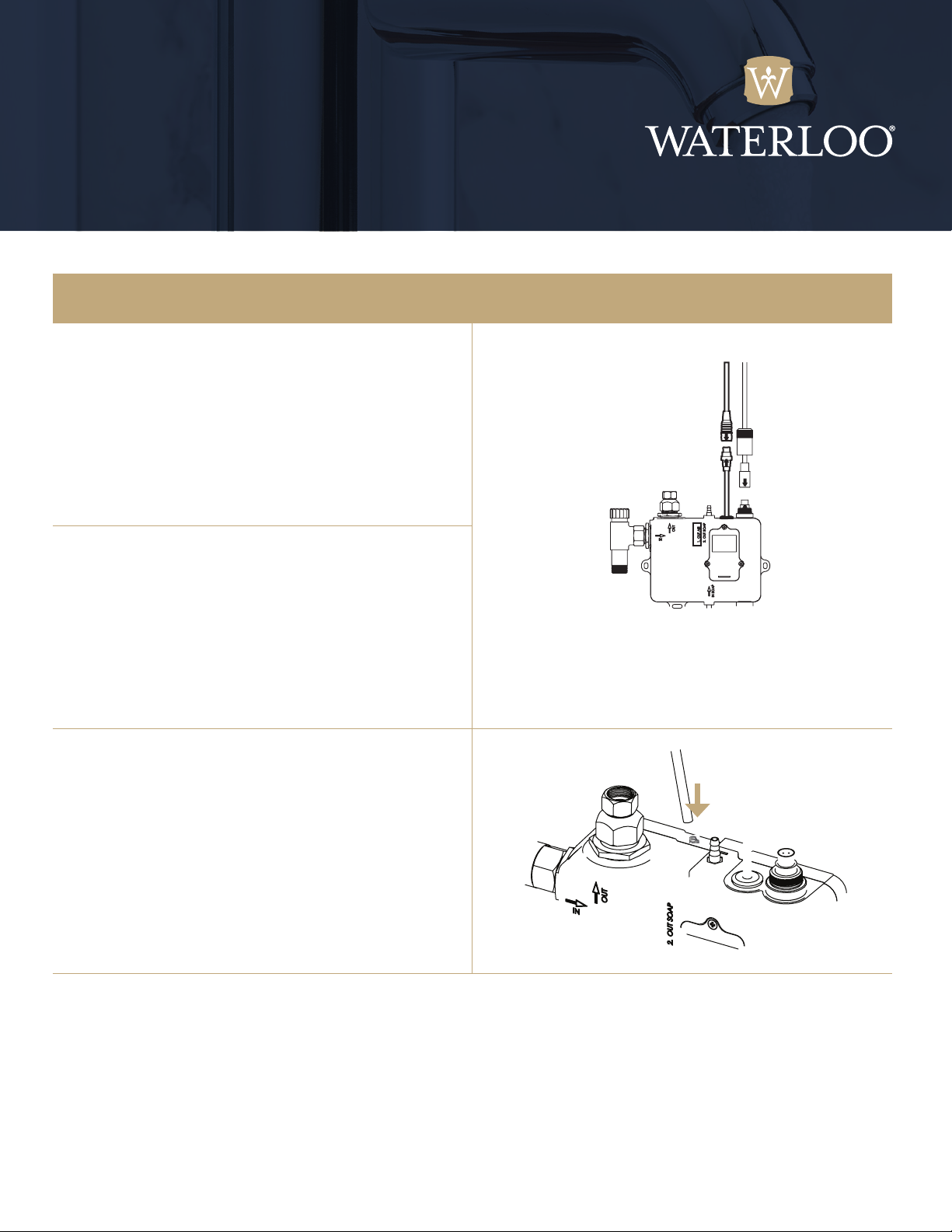
4. Secure the control module to the wall using
the provided template.
5. Make sure the control module is tightly fastened.
6. Tightly connect mixing valve (34) to water
(25) inlet of the control module.
7. Tightly connect the hot water hose (red) to the
hot side of mixing valve and do the same for the
cold water hose (blue). DO NOT BEND THE HOSES.
8. Connect the provided rubber washer (35) to
the outlet for water (16) on the control module
and tighten the outlet hose (11) to it. MAKE
SURE TO USE THE PROVIDED RUBBER WASHER.
Dual Sensor
Water/Soap Dispenser
Installation Manual
Installation Diagram
9. Connect tightly the head of sensor cable for
soap (white) of the spout body (13) to the
sensor connector for soap dispenser (18) of
the control module.
ATTENTION:
Align the direction of the arrow of each head between spout
body and control module. Make sure each head of spout
body is connected correctly to each head of control module.
10.Connect tightly the head of sensor cable for
faucet (14) of the spout body to the sensor
connector for faucet (19) of the control module.
11.Connect soap tube (12) of spout body to soap
outlet (17) of the control module and fit tightly
by using the provided clip fastener (37).
Dual Sensor
Water/Soap Dispenser
Installation Manual
Installation Diagram
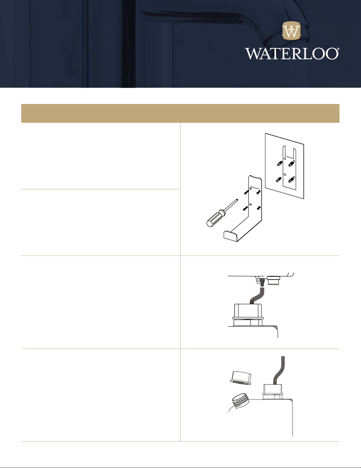
Soap canister mount installation.
12.Drill a screw hole in the wall by using “template
for soap canister mount.”
13.Screw in the soap canister mount (29) and make
sure it is tightly fastened and does not wobble.
14.Connect the provided black tube (36) to soap
outlet (28) to control module of soap canister and
fit tightly by using the provided clip fastener (37).
Connect the other side of the black tube to the inlet
for soap of control module (24) and fit tightly by using
the provided clip fastener (37).
15.Open the refill cap (32) and pour foaming soap into
soap canister. After refilling, replace refill cap.
NOTE: ONLY USE FOAMING SOAP.

Dual Sensor
Water/Soap Dispenser
Installation Manual
Installation Diagram
16.Place the soap canister on the soap canister
mount (29).
17.Insert the fixation pin (30) into the fixation tab
at the bottom of soap canister.
18.Connect AC adapter to the the power inlet (23)
of the control module.
The control module will start adjusting sensing
distance when power on. Manual sensor distance
adjustments may be required.
Dual Sensor
Water/Soap Dispenser
Installation Manual
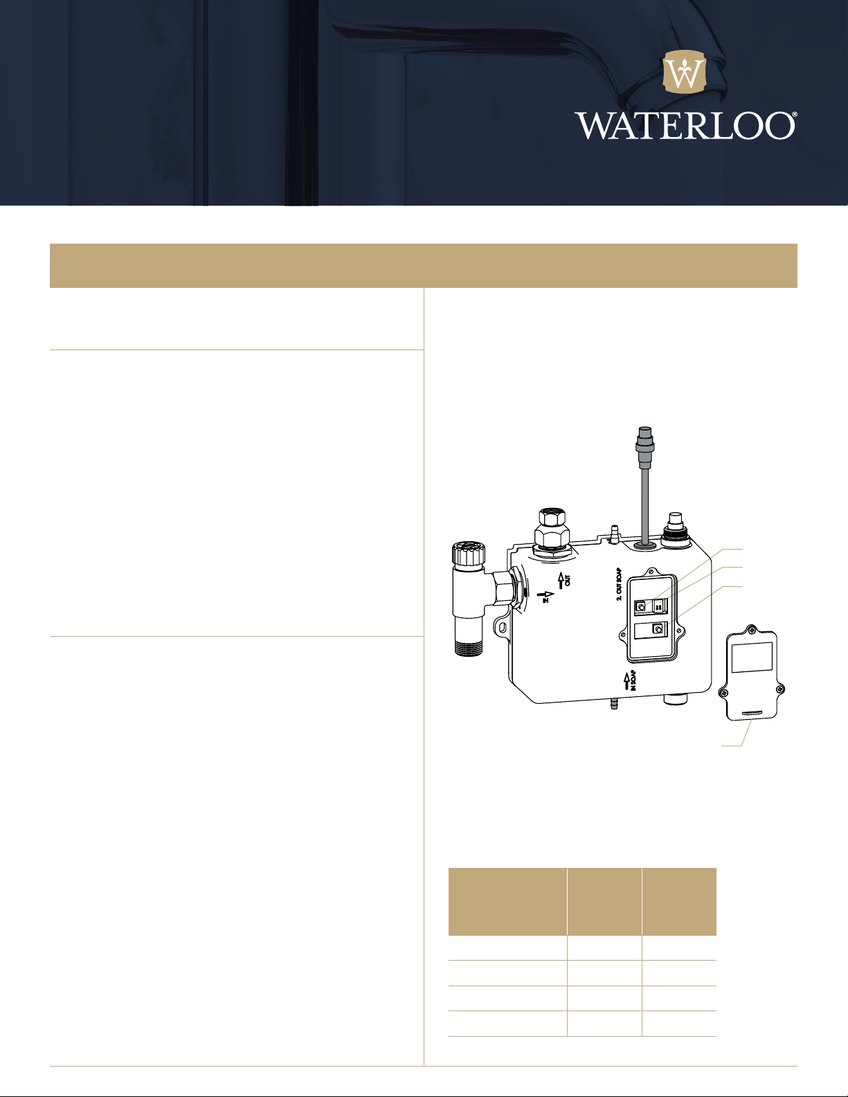
System Setup
1. Remove the Dial Cover.
The system is a digital system. Do NOT attempt to
tamper with the electronic components in risk of
damaging the components.
2. Setting the Faucet Sensor Distance
a. Press and hold the faucet system reset/purge
button (22) for about 5-7 seconds to clear CPU setting
memory, LED on sensor will turn on and stay lit to enter
setting mode.
b. Release button, LED will turn off, place your hand at
desired sensing distance, LED is flashing and wait until it
stays lit to complete new setting.
c. If your hand leaves sensing position range, water delay
will cut off after 2 seconds. Please reset to shorten sensing
distance and ensure water cut off time adjusts to 1 second.
d. Remove your hand and test new setting.
e. Factory default sensing distance is 4 in.
3. Soap Dispenser Sensor Setup
Distance setting:
a. Press and hold soap system reset/purge button (20)
for 2 seconds (LED on sensor is flashing).
b. Press the reset/purge button again to enter setup mode,
Place your hand at the desired sensing
distance, LED will flash when the new setting is complete.
c. Test the new setting.
Continuously dispensing soap setting:
a. Press and hold the soap system reset/purge button
(20) for 5 seconds (LED on sensor stays lit) to activate
continuously dispensing soap.
b. If want to stop dispensing soap, press and hold soap
system reset/purge button (20) again for 2 seconds.
Important note: The soap dispenser will dispense soap
automatically for one time every 12 hours to prevent clogging.
Soap system DIP switch (21) is for soap dispensing time
setting, Setting chart to the right. Factory default setting:
1 seconds. After setting, install back the dial cover.
20.
21.
22.
15.
Adjust the time of
dispensing soap Switch 1 Switch 2
0.5 seconds Off Off
1.2 seconds On Off
1.5 seconds Off On
2 seconds On On
Dual Sensor
Water/Soap Dispenser
Installation Manual
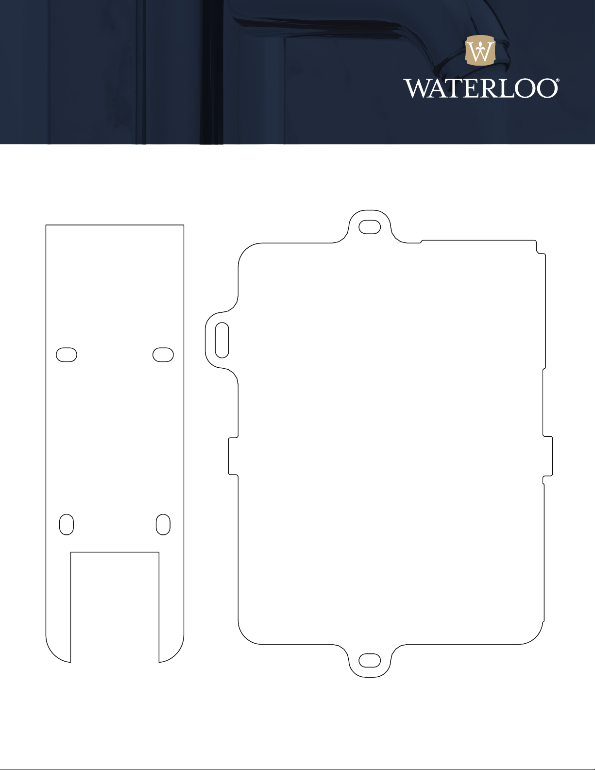
Template for Soap
Canister Mount
Template for Control Module
This manual suits for next models
1
Table of contents
Popular Dispenser manuals by other brands

Silver King
Silver King Majestic SK12MAJ Technical manual and replacement parts list

Franke
Franke F3Dn Twin Service manual

STIEBEL ELTRON
STIEBEL ELTRON UltraHot Plus Operation and installation instructions

DAN DRYER
DAN DRYER 282 installation guide

Essity
Essity Tork 473208 manual

CBS
CBS SD300BU-88 COMPONENT MAINTENANCE MANUAL WITH ILLUSTRATED PARTS LIST


